An Image of Handwritten Numeral (HN) converts to a binary image with .... To extract object features we need an image that has undergone ..... Online Character.
International Journal of Computer Applications (0975 – 8887) Volume 83 – No 10, December 2013
A Fuzzy Logic based Handwritten Numeral Recognition System Mahmood K Jasim
Anwar M Al-Saleh
Alaa Aljanaby
Department of Mathematical & Physical Sciences College of Arts & Sciences University of Nizwa, Oman
Department of Computer Science College of Sciences Al-Mustansiriyah University Iraq
Department of Mathematical & Physical Sciences College of Arts & Sciences University of Nizwa, Oman
ABSTRACT In this paper, a delayed treatment to handwritten numerals with fuzzy logic has been provided. The patterns which used in this system consisted 100 patterns of 10 numerals (0 to 9). They were taken from 10 different subjects and converted by the scanner to computer into 30×20 binary patterns. We used off-line system in take the patterns. The recognition rate is 94%.
General Terms Image processing, Fuzzy logic
Keywords Handwritten numeral recognition
thickness, etc. Closed-form mathematical models tend to be inadequate for such a task because of the many possible representations of the same image. The paper presents an off-line system for the recognition of handwritten numerals with preprocessing steps uses fuzzy logic, and called Handwritten Numeral Recognition Using Fuzzy Logic (HRUFL). The rest of the paper is organized as follows. Section 2 provides the necessary details for constructing the proposed recognition system for handwritten numerals. The details of the HRUFL implementation have been presented in Section 3. Test result with the discussion is given in Section 4 while, Section 5 is the conclusion.
1. INTRODUCTION
2. HANDWRITTEN NUMERAL RECOGINITION SYSTEM
Pattern recognition system is regarded as a system, whose input is the information of the pattern to be recognized, and output is a class to which the entered pattern belong [1, 2]. One of the important fields in pattern recognition is character recognition. It improves man-machine communication in addition to providing a solution for processing large amount of data automatically. The main objective of character recognition is the conversion of a graphical document into a textual one [2, 3]. Many systems have been proposed to recognize pattern. Some of these systems have been used the fuzzy logic. Most of the character recognition systems require preprocessing operations on the pattern [4, 5, 6, 7]. Preprocessing is an important step in pattern recognition systems in which fundamental features of pattern are extracted and/or enhanced, to classify and recognize unknown pattern [8].
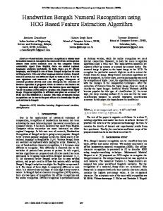
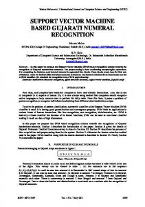
All the experiments performed in this research deal with handwritten numerals from 0 to 9. The patterns which used in this system consisted 100 patterns of 10 numerals (0 to 9). They were taken from 10 different subjects and converted by the scanner to computer into 30×20 binary patterns. We used off-line system in take the patterns. The character set to be recognized appears in Figure 1 as a study case. There are ten valid characters-numeric characters zero through nine. Figure 2 shows the block diagram of the proposed system.
Many tedious tasks can be made more efficient by automating the process of reading handwritten numerals. In such system an optical scanner converts each handwritten numeral to a digital image, and computer software classifies the image as one of the digits zero through nine. By reducing the need for human interaction, numeral-recognition systems can speed up jobs such as reading income tax returns, sorting inventory, and routing mail. Several steps are necessary to achieve this. A recognition system must first capture digital image of handwritten numerals. Before attempting to classify the numerals, some preprocessing image might be necessary. An algorithm must then classify each handwritten numeral as one of the ten decimal digits [8, 9].
An Image of Handwritten Numeral (HN) converts to a binary image with global threshold (Level). The next step is the thinning processing to extract the skeleton of the HN, so the HN becomes ready to undergo isolation. The output of this part of HRUFL is the image of the character with a fixed image size; each character is assigned a recognition stage by fuzzy logic.
Fig 1: Character Set to be Recognized.
2.1 Image Acquisition In numeral recognition systems, the first step is the acquisition of a digitized image of the text. Two methods are used in HRUFL in acquiring images. The first method is written the character by using paintbrush software tool, and converted to 2-D matrix. The second method uses a monochrome optical digital scanner.
Although a qualitative description of this process is straightforward, it cannot be easily reduced to a few simple mathematical rules. The difficulty results from the natural variations in human handwritten. A useful recognition system must be robust to alterations in size, shape, orientation,
36
International Journal of Computer Applications (0975 – 8887) Volume 83 – No 10, December 2013 regions by simple threshold. Let (x,y) be an image of any digitized trademark, then a new threshold image is given by: ……. (1) Where T an initial value of the threshold. To make segmentation more robust, the threshold should be automatically selected by the system. Therefore, automatic threshold has been applied. A threshold scheme that selects a proper value for each image without human intervention is called an automatic threshold scheme. It analyzes the gray value distribution in an image, by using a histogram of the gray value, to select the most appropriate threshold. If the image contains one object and a background having homogeneous intensity, it usually possesses a bimodal. Using the following steps chooses the threshold (called Iterative Threshold Selection): 1. Select an initial estimate of the threshold T. A good initial value is the average intensity of the image. 2. Partition the image into two regions, R1 and R2, using the threshold T. 3. Calculate the mean gray values µ1 and µ2 of the partitions R1 and R2. 4. Select a new threshold: ..… (2) 5. Repeat steps 2-4 until the mean values µ1and µ2 in successive interactions do not change. Fig 2: HRUFL Stages for Preparation of Handwritten Numerals
2.2 Image Preprocessing Most images require some manipulation before the application of any recognition technique. The process of preparing the image and improve its quality in order to eliminate irrelevant information and to enhance the selection of the important features for recognition is known a preprocessing. Preprocessing is performed to improve the robustness of features to be extracted. Also preprocessing steps are performed in order to reduce noise in the input images, and to remove most of the variability of the handwriting. The key function of preprocessing is to improve the image in ways that increase the chances for success of the other processing [10, 11]. The preprocessing includes some operations such as image thinning, image standardization, and others, these two operations are discussed in the following.
2.2.1 Convert the Image to a Binary Image In this part of HRUFL the producing is a binary image from indexed, intensity, or RGB image. To do this, it converts the input image to gray scale format (if it is not already an intensity image), and then converts this gray scale image to binary by threshold. The output binary image has values of 0 (black) for all pixels in the input image with luminance less than (Level) and 1 (white) for all other pixels. Where the (Level) is a normalized intensity value then it lies in the range [0, 1], regardless of the class of the input image. Thresholding is one of the most important approaches to segment an image, which contains an object having homogeneous intensity and a background with a different intensity level. The digitized image has the intensity level from 0 to 255. An image as such, can be segmented into two
2.2.2 Image Denoising Perform cleaning operation to the binary image to remove isolated pixels (individual 1's that are surrounded by 0's), such as the center pixel in this pattern: 0
0 0
0
1 0
0
0 0
The noise which appears not only from the natural effects of handwritten, but also by means of other factors such as scanner resolution, printer and paper quality may connect the symbols or breaks one symbols into pieces.
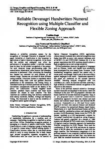
2.2.3 Image Thinning This process is considered important process in a preprocessing part. Thinning of a binary pattern is generally considered as a process of iterative deletions of pixels along the edge of the pattern until the pattern is thinned to line drawing, i.e. skeleton. . Figure (3) shows an originally scanned image and the resulting final skeleton after applying the thinning algorithm.
2.2.4 Number Isolation To extract object features we need an image that has undergone image segmentation and any necessary morphological filtering. This will provide clearly defined objects, which can then be labeled and processed independently. After all the objects in the image are labeled, it can treat each object as a binary image by assuming that the labeled object has a value of 1 and that everything else is 0. The labeling process requires defining the desired connectivity and then to scan the image and label connected objects with the same symbol.
37
International Journal of Computer Applications (0975 – 8887) Volume 83 – No 10, December 2013
Fig 4b: Current pixel is A. Pixels B, C, and D are neighboring ones
(a)
(b)
The labeling algorithm requires an UPDATE function to keep track of objects with more than one label. Multiple labeling can occur during sequential scanning, as shown above on the J shaped object. We label two different objects until we reach the pixel marked X, where we discover that objects 1 and 2 are connected.
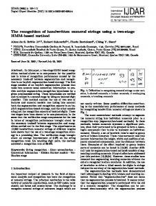
Fig 3: Illustration of the Thinning Process: (a) The Image before Thinning Process. (b) The Image after Thinning Process. Applying the algorithm which is explaining in the flowchart in Figure (4a) below to the label of the objects in the image (see Fig 4b). For this algorithm any area not of interest in the image has been masked out by setting the pixels equal to zero. The UPDATE block in the flowchart refers to a function that will keep track of objects that have been given multiple labels. This can occur with sequentially scanning of the image until after different parts of the object have already been labeled, Figure (5).
1
1
1
1
1
1
1
1
2
2
1
1
2
2
1
1
2
2
2
2
X
Scan left to right, and top to bottom Fig 5: Multiple Labels
2.2.5 Image Standardization After we have labeled the objects, we have an image filled with object numbers, the image standardization will take place, by changing the size of the digit image to a suitable size for a later recognition. This image is used to extract the features of interest. This procedure changes the dimensions of the image. The image data is stretched or compressed as necessary, to fit the new dimensions. The new width is 20 pixels, and the new height is 30 pixels, to specify the new dimensions. In Figure (6) Image (a) of size (36×15) and image (b) of size (20×20) are standardize to size (30×20).
Fig 4a: Flowchart of Labeling Algorithm
Fig 6: Illustration of the Standardization process: (a), (b) two Images before the Standardization process. (a’), (b’) the Images after the Standardization process.
38
International Journal of Computer Applications (0975 – 8887) Volume 83 – No 10, December 2013 At the end of this stage each character is right–justified in a 2D matrix with the same size of the BMP image and having entries of 1's and 0's representing the white pixels and black (background) pixels, respectively.
2.2.6 Feature Extraction In a former paper [12], the authors proposed the transition calculation and sum of pixels of an image as a feature detector, fuzzy logic technique as a feature analyzer, and extraction the most useful information as outputs for classifier process. Handwritten numerals recognition system has been designed and implemented and a high degree of accuracy has been gained using fuzzy logic. In that work, the authors have presented a reliable and relatively simple method for generating the fuzzy rule-based description of handwritten characters. Here, the six input variables are T1, T2, T3, T4, SOP1 and SOP2. Ten valid output variables, one for each of the ten characters to be recognized, are defined. Table 1 shows the relationship between fuzzy input variables and fuzzy output variables. Table 1: Fuzzy Set Association Char
0
T1
Larg
T2
Med
e 1
Sma
Med
ll 2
3
4
6
8
9
Larg
Sma
e
ll
------
------
-
-
Larg
Sma
Larg
ll
e
ll
e
Larg
Sma
------
------
e
ll
Sma
Med
SOP
SOP
1
2
Large
Large
Small
Small
Large
Large
Large
Med
Large
-------
-------
Med
Large
Max
HRUFL is the fuzzy system with six input variables, one output variable, seventeen input membership functions, ten output membership functions and ten fuzzy rules. The first input variable is T1. The valid range of values for T1 is defined as 0 to 30. The input variable T1 has two membership functions. The first input membership function definition is: ….. (3) The name of the input membership function is Small, and the type is trapezoidal fuzzy set. Small starts with value 1 at the smallest valid value (10), and remains 1 until value (19), when it begins to ramp down, eventually reaching 0 at value (21). The second input membership function definition is:
The name of the input membership function is Large, and the type is trapezoidal fuzzy set. Large starts with value 0 at the smallest valid value (19), when it begins ramp up, eventually reaching 1 at value (21). Large remains 1 until value (30). Figure 7 illustrates the input variable T1 and its membership functions. Table 2 describes the member functions of the six input variables and shows the figure associated with each variable.
Larg
Larg
e
e
Sma
Larg
Sma
Larg
ll
e
ll
e
Larg
Med
Sma
Larg
ll
e
------
------
e 7
T4
Sma
ll 5
T3
3. SYSTEM IMPLEMENTATION
Larg
Sma
e
ll
Larg
Larg
Larg
Sma
e
e
e
ll
Sma
Larg
Larg
Sma
ll
e
e
ll
Fig 7: The Input Variable T1 Med
Small
Max
Max
Large
Med
-
39
International Journal of Computer Applications (0975 – 8887) Volume 83 – No 10, December 2013 0 T3
0..30
MF1
4 4
Small
9
10 12 MF2
10 12
Large
T4
-30..0
MF1
MF2
Small
trapezoidal
25 25 -30 30 -21 -19 -21
Large
10
-
19 -10 -10 SOP1
0..100
MF1
0 0
Small
11
14 26 MF2
14 26
Med
MF3
Fig 8: The Input Variable T2
Large
trapezoidal
35 40
Table 2: Input variables and their member functions MF4
Fun.
Name
Type
Par.
of
List
Fuzzy
65 73
Max
100 SOP2
0..100
MF1
0 0
Small
T2
-30..0
MF1
Large
-20
MF3
Med
Large
Large
30 30 8
15 18
Med
52 59 MF3
19 21
30 -23
MF2
MF2
19 21
-30 -
Small
7
MF4
Max
trapezoidal
MF2
trapezoidal
0..30
trapezoidal
T1
10 10
Small
12
15 18
set MF1
65 73
100 Figure
Range
Variable
Membership functions
35 40
52 59 65 70 65 70 100 100
-23 20 -12 -10 -12 10 0
40
International Journal of Computer Applications (0975 – 8887) Volume 83 – No 10, December 2013
Fig 9: The Input Variable T3 Fig 11: The Input Variable SOP1
Fig 10: The Input Variable T4 Fig 12: The Input Variable SOP2
41
International Journal of Computer Applications (0975 – 8887) Volume 83 – No 10, December 2013 HRUFL is with one output variable. The name of the output variable is Char. The variable is assigned the meaningless unit of Character. The range of Char is specified as 0 to 10. The output variable Char has ten membership functions. The first output membership function definition is: …. (5) The name of the output membership function is Zero, and the type is triangular fuzzy set. Zero starts with value 1 at the smallest valid value (0), when it begins ramp down, eventually reaching 0 at value (1). Table 3 describes the details of the ten member functions and the illustration the member functions of the output variable is shown in Figure 13. Table 3: Output variable’s member functions
Function
Membership functions Name Type of Fuzzy set
Parameters
MF1 MF2
Zero One
triangular triangular
0 0 1 0 1 2
MF3 MF4 MF5 MF6 MF7 MF8 MF9
Two Three Four Five Seven Eight Nine
triangular triangular triangular triangular triangular triangular triangular
1 2 3 2 3 4 3 4 5 4 5 6 6 7 8 7 8 9 8 9 10
4. TEST RESULT The most productive testing technique for fuzzy systems is empirical. To test HRUFL, a text file of test data was supplied to the HRUFL simulator and generated outputs were compared to the expected outputs. A group of ten data sets was created as a starting point. This group is shown in the listing below. The input data sets correspond, in order, to the ten fuzzy rules in the fuzzy inference unit listing. Therefore, proper selection of input values T1 through T4, SOP1and SOP2 should generate the output 0 through 9 in that order. The values shown are center points for the fuzzy set specified by a given rule, and thus represent a set of input data that HRUFL should find easy to classify. This group of ten data sets was then duplicated and modified to check for proper operation across the range of character data. The listing shows only the initial ten data sets. In each group of data sets, one input variable (say, T1) was taken to the lower limit, with all others held at the upper limit.
0 23 -17 17 -23 59 61 1 13 -13 00 -00 12 14 2 18 -08 08 -19 56 66 3 25 -25 00 -00 53 24 4 17 -17 14 -17 53 56 5 18 -08 07 -17 71 42 6 23 -14 07 -15 61 84 7 27 -27 00 -00 29 03 8 21 -09 15 -25 77 77 9 15 -06 19 -26 59 36
Fig 13: The Output Variable Char
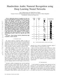
For example let take the input variable vector [13 –13 00 –00 12 14], where (13) refer that the input variable T1 is 13 (T1 = 13), (-13) refer that the input variable T2 is –13 (T2 = -13), (00) refer that the input variable T3 is 00 (T3 = 00), (-00) refer that the input variable T4 is also 00 (T4 = 00), (12) refer that the input variable SOP1 is 12 (SOP1 = 12), and at last (14) refer that the input variable SOP2 is 14 (SOP2 =14). These are the inputs for each of the rules which defined above. Below in Figure 14 the membership functions of the inputs are illustrated again with the input indicated with dark vertical lines. Each rule takes the inputs and determines the appropriate output. The outputs of the rules have grades of membership that are determined by the input grades. Each output grades is equal to the lowest grade of its inputs. The output grade value is found this way because a logical “and” is defined as “belonging to all sets”. The lowest grade value is a member to all of the grade value sets. Rule 2, is the only rule with non-zero outputs. Rules 1, 3, 4, …, and 10 have a grade of zero, then the output grade is zero. After the output of each rule is determined, all of the outputs are then combined to form the Logical Sum. All of the outputs are combined using the OR function. The logical “OR” means “belonging to any set”. Therefore, the largest value of each membership set contributes to the Logical Sum. In this example Rule 2 has a larger grade value so will therefore contribute to the Logical Sum. First, the center of area of the Logical Sum is located. Next, the location of this center of area is compared to the full
42
International Journal of Computer Applications (0975 – 8887) Volume 83 – No 10, December 2013 range of output. The center of area for this example, is the set, which its name is One, then the output is the character One.
6. REFERENCES [1] Bandara G.E, Pathirana S.D., Ranawana R. M. 2002. Use of Fuzzy Feature Descriptions to Recognize Handwritten Alphanumeric Characters. In Proceedings of the 1st Conference on Fuzzy Systems and Knowledge Discovery, Singapore. [2] Belal K. Elfarra and Ibrahim S. I. Abuhaiba. 2013. New Feature Extraction Method for Mammogram Computer Aided Diagnosis. International Journal of Signal Processing, Image Processing and Pattern Recognition, Vol. 6, No. 1. [3] Rajashekararadhya, S. and Ranjan, P. 2009. Zone based feature extraction algorithm for handwritten numeral recognition of kannada script. In proceedings of the Advance Computing Conference (IACC 2009). IEEE International, pages 525–528. [4] L. M. Lorigo and V. Govindaraju. 2006. Offline Arabic handwriting recognition: a survey. IEEE Transactions on Pattern Analysis and Machine Intelligence, vol. 28, no. 5, pp. 712 - 724. [5] Bandara G.E., Pathirana S.D., Ranawana R. M. 2002. A Short Method for On-line Alphanumeric Character Recognition. NAFIPS – FLINT 2002, New Orleans, USA. [6] Pal, U., Sharma, N., Wakabayashi, T., and Kimura, F. 2008. Handwritten character recognition of popular south indian scripts. In Doermann, D. and Jaeger, S., editors, Arabic and Chinese Handwriting Recognition, volume 4768 of Lecture Notes in Computer Science, pages 251– 264, Springer Berlin / Heidelberg.
Fig 14: if/then Results for Rules with all Zero and Nonzero outputs
5. CONCLUSION The main challenge in handwritten character recognition involves the development of a method that can generate descriptions of the handwritten objects in a short period of time. Due to its low computational requirement, fuzzy logic is probably efficient method available for character recognition. Fuzzy systems are robust; even if some rules are removed from the rule map, the system could still work properly; fuzzy systems are also robust toward changing conditions in the environment and provide simple and effective methods for handwritten character recognition because fuzzy features can represent the characters. The tedious task associated with using fuzzy logic for character recognition is the building of the rule-base that would describe the characters to be recognized. The problem is complicated as different people write the same character in complete different ways. Another problem associated with handwritten numeral character recognition is the difficulty in associating exact fuzzy parameters to certain characters, due to differences associated with the way they are written by different people. The method so tested was found to be extremely reliable and relatively simple method for generating the fuzzy description of handwritten numerals.
IJCATM : www.ijcaonline.org
[7] Jan J. 1998. Tutorial on fuzzy logic. Technical University of Denmark of Automation, Report No. 98-E868. [8] Yadana T. and San S. Y. 2010. High Accuracy Myanmar Handwritten Character Recognition using Hybrid approach through MICR and Neural Network. International Journal of Computer Science Issues (IJCSI), Vol. 7, Issue 6. [9] Muthumani .I , Uma Kumari C.R. 2012. Online Character Recognition of Handwritten Cursive Script. International Journal of Computer Science Issues (IJCSI), Vol. 9, Issue 3, No 2. [10] Lauer, F., Suen, C. Y., and Bloch, G. 2007. A trainable feature extractor for handwritten digit recognition. Pattern Recognition, 40(6):1816–1824. [11] Pal, U., Sharma, N., Wakabayashi, T., and Kimura, F. 2008. Handwritten character recognition of popular south indian scripts. In Doermann, D. and Jaeger, S., editors, Arabic and Chinese Handwriting Recognition, volume 4768 of Lecture Notes in Computer Science, pages 251– 264, Springer Berlin / Heidelberg. [12] Mahmood K Jasim, Anwar M Al-Saleh and Alaa Aljanaby. 2013. A Fuzzy Based Feature Extraction Approach for Handwritten Characters. International Journal of Computer Science Issues (IJCSI), Vol. 10, Issue 4, No 1.
43