A GaAs MMIC-Based Inline RF MEMS Power Sensor Zhiqiang Zhang, Xiaoping Liao*, Lei Han and Shi Su Key Laboratory of MEMS of Ministry of Education, Southeast University Nanjing 210096, China *Corresponding E-mail:
[email protected] Abstract—In order to improve microwave characteristics and the frequency response of the output thermovoltage at X-band, an inline RF MEMS power sensor with the impedance matching and compensating capacitance structures is presented in the paper and the sensor is accomplished with GaAs MMIC process. The measured results show that the reflection loss of the sensor is less than -17 dB and the insertion loss is less than 0.8 dB at Xband. A sensitivity of more than 26 µV·mW-1 and a resolution of 0.316 mW are obtained at 10 GHz. The frequency response of the sensor is relatively flat, and the modulation depth under amplitude modulation (AM) signals influences the output directly. The measured mechanical resonant frequency (fo) of the MEMS membrane is 110 kHz. In addition, the measured results show that the intermodulation (IM) power for Δf = 80 kHz, P1 = P2 = 10 dBm of the signals is less than -52 dBm. And the input third-order intermodulation intercept point (IIP3) is a large value at Δf = fo, so the inline RF MEMS power sensor for Δf > fo will not generate significant intermodulation distortion.
I.
INTRODUCTION
Radio frequency (RF) power sensors play an important role in wireless applications like power monitoring, gain control or circuit protection. Most of modern personal communication and radar systems require that the RF signal is available during power detection. In recent years, some typical inline RF power sensors based on MEMS technology have been proposed. Dehe A et al. [1-3] developed the inline inserted sensors for the measurement of the power dissipated by the intrinsically ohmic losses of the center conductor of a coplanar waveguide (CPW) line, based on Seebeck effect. But the sensors have to utilize complex process and are not compatible with a traditional GaAs or Si technology. Moreover, the thermal performance of the sensors can be increased at the sacrifice of the microwave performance of the CPW line. Fernandez L J et al. [4-6] and Vaha-Heikkila T et al. [7-8] presented the inline capacitive sensors for the measurement of the capacitive change of a moveable membrane suspended above a CPW line where the signal was traveling, based on the capacitive MEMS technology. But the performance of the sensors has to strongly depend on the fabrication process. Moreover, the reflection and insertion losses will increase due to the capacitance change when the
978-1-4244-5335-1/09/$26.00 ©2009 IEEE
microwave power which is traveling through the membrane is increased. Therefore, the most problems of both sensing principles are a trade-off between the microwave performance and the sensitivity. For solving the problem, L. Han et al. [9] proposed a novel inline microwave power sensor for the measurement of a certain percentage of the incident microwave power coupled by a MEMS membrane suspended above a CPW line, based on Seebeck effect. The power sensor consists of two independent steps: the coupling step and the measurement step. The two steps make it possible for the power sensor to separately design the microwave performance and the sensitivity. However, all of these sensing principles do not provide any method to improve the frequency response of the RF power sensor, and most of them do not utilize the impedance matching method to reduce microwave losses. These sensors can be embedded into the RF circuits for the purpose of inline power detection, gain control or circuit protection. However, most of these circuits operate at the higher level of the power, so the linearity of the power sensors is a critical parameter to prevent distortions or interchannel interferences. In this paper, the sensing principle of the inline RF MEMS power sensor is that the sensor measures a certain percentage of the incident microwave power coupled from the center conductor of a CPW line by a MEMS membrane and then converted to the output thermovoltage by thermopiles, based on Seebeck effect. The impedance matching structure and the compensating capacitance structure of the power sensor are presented in order to improve microwave characteristics and the frequency response of the output thermovoltage at X-band. The sensor has many advantages such as higher sensitivity, wider frequency response, lower insertion and reflection losses, excellent linearity, and compatibility with GaAs MMIC technology. And the measured results also show that the modulation depth under amplitude modulation (AM) signals influences the sensitivity of the sensor directly. Furthermore, the paper presents an experimental study of nonlinear effects generated by the inline power sensor to prevent interchannel interferences in the following circuit systems. The experiment
1705
IEEE SENSORS 2009 Conference
The power sensor consists of a microwave power coupler and two indirectly thermoelectric microwave power sensors. The microwave coupler that is similar to a capacitive shunt MEMS switch couples a certain percentage of the incident microwave power into two inputs of the thermoelectric power sensors by a suspended MEMS membrane. Then the two indirectly thermoelectric power sensors convert the coupled power into heat and result in the output thermovoltage respectively, based on Seebeck effect. It should be noticed that the width of the MEMS membrane will be designed for the realization of the desirable sensitivity, and the length of the MEMS membrane will be designed to be very short as a result that the coupling capacitance between the membrane and the center conductor of the CPW line is insensitive to the incident power of RF signals. In order to reduce the effect of the suspended membrane on the microwave performance of the sensor, an impedance matching method by modifying the gap size of the CPW line before and after the MEMS membrane is proposed. In order to further improve the frequency response of the output thermovoltage, a compensating capacitance method by adding an open-circuital transmission line is proposed. Due to the compensating capacitance on the order of several fF, directly adding a MIM (metal-insulator-metal) capacitor will strongly depend on the process and can cause a significant deviation between the fabricated capacitance and the desirable capacitance, ultimately result in the deterioration of microwave performance. According to the theory of the transmission line, an open-circuital transmission line can be equivalent to a capacitor. The capacitance compensated by an open-circuital transmission line can be minimally dependent on the process.
0
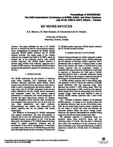
0.0 Measured S11 Measured S21
-5
-0.5
-10 -15
-1.0
-20 -1.5 -25 -30
8
9
10
Frequency (GHz)
-2.0 12
11
Fig. 2. Measured S-parameters of the inline power sensor.
MEASUREMENT OF MICROWAVE PERFORMANCE AND POWER HANDLING
6
In this paper, the inline RF MEMS power sensor is fabricated using GaAs MMIC process with two-layer metal, as described in detail in [11]. The thermopiles are made of gold and n+ GaAs with a doping concentration of 1.0×1018 cm−3. The termination matched resistor (50 ohm) is made of TaN. A. Measurement of Microwave Performance Microwave performance of the inline RF MEMS power sensor is measured using an Agilent HP8719ES network analyzer and a Cascade Microtech GSG probes station. The measurement of the microwave performance includes the measurement of reflection losses (S11) and insertion losses (S21) of the signal applied to the sensor. Fig. 1 shows a SEM photograph of the inline power sensor with the impedance matching and compensating capacitance structures. Fig. 2 shows the measured S-parameters of the inline power sensor. In Fig. 2, the measured reflection loss of the sensor is less than -17 dB and the insertion loss is less than
8 GHz 9 GHz 10 GHz 11 GHz 12 GHz
5
Thermovoltage (mV)
III.
Fig. 1. SEM photograph of the inline power sensor.
S (dB) 21
II. DESIGN OF IMPEDANCE MATCHING AND COMPENSATING CAPACITANCE STRUCTURES
0.8 dB at X-band due to the impedance matching structure. A certain percentage of the total transmitted power is coupled by the MEMS membrane and then converted to the output thermovoltage, so the insertion loss is slightly high.
S11 (dB)
demonstrates the power sensor will not generate significant intermodulation distortion in some cases.
4 3 2 1 0
0
50
100
150
Microwave Power (mW)
200
Fig. 3. Measured output thermovoltage as a function of microwave power under different frequencies.
B. Power Handling Power handling of the inline RF MEMS power sensor is measured using an Agilent E8257D PSG analog signal
1706
generator, a Cascade Microtech GSG probes station, a 50 ohm loaded resistor, and a Fluke 8808A digital multimeter. The power handling includes the measurements of sensitivities at different frequencies and the effect of the modulation depths under AM signals on the sensitivities. Fig. 3 shows the measured output thermovoltage as a function of the microwave power for the inline power sensor under different frequencies. The measurement demonstrates the excellent linearity of the output thermovoltage with respect to the input microwave power at X-band, and a sensitivity of the sensor is more than 26 µV·mW-1 at 10 GHz. But the sensitivity is slightly decreased because of the opencircuital transmission line dissipating some coupled power. A resolution of the power sensor is on the order of 0.316 mW and is mainly limited by the heat noise of the thermopiles of the indirectly thermoelectric power sensors. In Fig. 3, the variation of the sensitivity of the power sensor at X-band is reduced due to the compensating capacitance structure, and it means that the flatness of the response with respect to the frequency is obtained. 3.5 Origin Input Signal AM Signal &Depth=0.1% AM Signal &Depth=40% AM Signal &Depth=80%
2.5 2.0 1.5 1.0 0.5 0.0
0
20
40
60
Microwave Power (mW)
80
Fig. 4. Measured output thermovoltage as a function of the microwave power under different AM depths at 10 GHz.
Fig. 4 shows the measured output thermovoltage as a function of the microwave power for the inline power sensor under different AM depths at 10 GHz. The measurement demonstrates the increase of the output thermovoltage with the modulation depth at 10 GHz when AM signals with the modulated frequency of 10 kHz are applied to the power sensor. The trend is in accordance with that calculated by the AM signal equation in [12]. Under the AM signals, the sensitivity of the sensor is almost equal to the origin input signal in the AM depth of 0.1% at 10 GHz, but increases to 30 µV·mW-1 in the AM depth of 40% and reaches 35.5 µV·mW-1 in the AM depth of 80%. IV.
2kg 02 (3) φCZ0 Fig. 5(c) shows the measured results of the IM power. Both the output power and the IM power of the measurement versus the input power could be plotted and the IIP3 could be deduced. From the measurement results, we can deduce that the IIP3 is +28.7 dBm at Δf = 10 kHz, but reaches a large value at Δf = fo = 110 kHz and it means that the inline RF MEMS power sensor will not generate significant intermodulation distortion. Fig. 5(d) shows the IM power versus Δf. In Fig. 5(d), IM power fall off remarkably as Δf increases from 2 kHz to 110 kHz, but slightly from 120 kHz to 500 kHz for P1 = P2 = 4 dBm and 6 dBm. The measurement further demonstrates that the inline RF MEMS power sensor for Δf > fo will not generate any significant intermodulation distortion in most of the multichannel communication systems. IIP3 =
INTERMODULATION DISTORTION
Intermodulation distortion of the inline RF MEMS power sensor is measured using two Agilent E8257D PSG analog signal generators, an Agilent E4447A PSA series spectrum analyzer, a Cascade Microtech GSG probes station, and an Agilent 11667C power splitter. Fig. 5 shows the measurements of IM products.
1707
80
Vib-Velocity Magnitude (m/s)
Thermovoltage (mV)
3.0
Considering the case of two incident RF signals on the CPW line of the microwave coupler (Vin = V1sin(ω1t) + V2sin(ω2t)), and assuming V1 = V2, the IM power at 2f1 - f2 and 2f2 - f1 can be easily calculated as φC 2 P Pint er mod = sideband = (V1V2 ) (1) Psignal 4kg 02 where C is the capacitance of the MEMS membrane, g0 and k are the initial height and the spring coefficient of the membrane, φ is the output phase of the transmission coefficient of the microwave coupler and is given by [12-13] ωCZ 0 φ=− (2) 2 In Fig. 5(a), the measured mechanical resonant frequency fo of the MEMS membrane is 110 kHz by the laser doppler vibrometer (LDV), employing the theory of piezoelectric ceramic (PZT) which results in the vibration of the membrane. And the mechanical resonant frequency of the substrate is de-embedded from the measurement results. Fig. 5(b) shows the output spectrum (Δf = |f2 - f1| = 80 kHz, P1 = P2 = 10 dBm) with the IM power which is less than -52 dBm. The two tone third order intermodulation intercept point (IIP3) corresponds to the value Psignal, where Psignal = Pintermod, and could be easily derived from (1)
60
40
20
0
0
50
100
150
200
Frequency (kHz)
(a)
250
300
process. The experiments prove the expected advantages such as higher sensitivity, wider frequency response, lower insertion and reflection losses, and excellent linearity. The modulation depth under AM signals influences the sensitivity of the power sensor directly. Furthermore, the experiment demonstrates that the inline RF MEMS power sensor for Δf > fo will not generate significant intermodulation distortion. ACKNOWLEDGMENT This work is supported by the National Natural Science Foundation of China (NSFC: 60676043) and the National High Technology Research and Development Program of China (863 Program, 2007AA04Z328).
(b)
REFERENCES [1] 40
Power (dBm)
20
[2]
0
-40 IM Product -60 -80
Compression
0
10
20
Pin (dBm)
[3]
Output Power Δ f =10 kHz Δ f =20 kHz Δ f =40 kHz Δ f =80 kHz Δ f =100 kHz Δ f =120 kHz Δ f =200 kHz
-20
30
[4]
[5]
40
[6]
(c)
-40
[7]
-45
Pin=4 dBm Pin=6 dBm
IM power (dBm)
-50
[8]
-55 -60
[9]
-65 -70
[10]
-75 -80
0
100
200
300
400
500
[11]
Δ f (kHz)
(d)
[12]
Fig. 5. Measurements of IM products. (a) Mechanical resonant frequency of MEMS membrane. (b) Output spectrum for P1 = P2 = 10 dBm and Δf = 80 kHz. (c) Measured results of the IM power. (d) IM power vs. Δf.
[13]
V.
CONCLUSION
In order to improve microwave characteristics and the frequency response of the output thermovoltage at X-band, an inline RF MEMS power sensor with the impedance matching and compensating capacitance structures is presented in the paper and the sensor is accomplished with GaAs MMIC
1708
A. Dehe, V. Krozer, K. Fricke, H. Klingbeil, K. Beilenhoff, and H. L. Hartnagel, “Integrated microwave power sensor,” Electron. Lett., vol. 31, no. 25, pp. 2187–2188, Dec. 1995. A. Dehe, K. Fricke-Neuderth, and V. Krozer, “Broadband thermoelectric microwave power sensors using GaAs foundry process,” in Proc. IEEE MTT-S Symp., 2002, vol. 3, pp. 1829–1832. A. Dehe, H. Klingbeil, V. Krozer, K. Fricke, K. Beilenhoff, and H. L. Hartnagel, “GaAs monolithic integrated microwave power sensor in coplanar waveguide technology,” in Proc. IEEE MTT-S Symp., 1996, vol. 1, pp. 161–164. L. J. Fernandez, J. Sese, J. Flokstra, and R.Wiegerink, “Capacitive MEMS application for high frequency power sensor,” in Proc. Micromech. Eur., 2002, pp. 252–255. L. J. Fernandez, E. Visser, J. Sese, R. Wiegerink, J. Flokstra, H. Jansen, and M. Elwenspoek, “Radio frequency power sensor based on MEMS technology,” in Proc. IEEE Sens. Conf., 2003, vol. 1, pp. 549–552. L. J. Fernandez, R. J. Wiegerink, J. Flokstra, J. Sese, H. V. Jansen, and M. Elwenspoek, “A capacitive RF power sensor based on MEMS technology,” J. Micromech. Microeng., vol. 16, no. 7, pp. 1099–1107, Apr. 2006. T. Vaha-Heikkila, J. Kyynarainen, A. Oja, J. Varis, and H. Seppa, “Capacitive MEMS power sensor,” in Proc. 3rd Workshop MEMS Millimeterwave Commun., 2002, pp. 336–339. T. Vaha-Heikkila, J. Kyynarainen, J. Dekker, P. Pekko, N. Guillaume, A. Oja, J. Varis, and H. Seppa, “Capacitive RF MEMS power sensors,” in Proc. 3rd ESA Workshop Millimeter Wave Technol. Appl., Circuits, Syst., Meas. Tech., 2003, pp. 503–508. L. Han, Q. A. Huang, and X. P. Liao, “A microwave power sensor based on GaAs MMIC technology,” J. Micromech. Microeng., vol. 17, pp. 2132–2137, 2007. J. B. Muldavin and G. M. Rebeiz, “High-isolation CPW MEMS shunt switches—Part 1: Modeling,” IEEE Trans. Microw. Theory Tech., vol. 48, no. 6, pp. 1045–1052, Jun. 2000. W. B. Zheng, Q. A. Huang, X. P. Liao, and F. X. Li, “RF MEMS membrane switches on GaAs substrates for X-band applications,” J. Microelectromech.Syst., vol. 14, no. 3, pp. 464–471, Jun. 2005. G. M. Rebeiz, RF MEMS Theory, Design, and Technology. Hoboken, NJ: Wiley, 2003. L. Dussopt and G. M. Rebeiz, “Intermodulation distortion and power handling in RF MEMS switches, varactors and tunable filters,” IEEE Trans. Microw. Theory Tech., vol. 51, no. 4, pp. 1247-1256, Apr. 2003.