ing data raises compelling computational challenges to Web search engines. ... have incorporated SIMD-based optimization into compression algorithms [Stepanov .... It first calculates the effective bit width b of the maximum integer in this se-.
A General SIMD-based Approach to Accelerating Compression Algorithms WAYNE XIN ZHAO, Renmin University of China XUDONG ZHANG, Yahoo! China DANIEL LEMIRE, Université du Québec DONGDONG SHAN, Alibaba Group JIAN-YUN NIE, Université de Montréal HONGFEI YAN, Peking University JI-RONG WEN, Renmin University of China Compression algorithms are important for data oriented tasks, especially in the era of “Big Data”. Modern processors equipped with powerful SIMD instruction sets, provide us an opportunity for achieving better compression performance. Previous research has shown that SIMD-based optimizations can multiply decoding speeds. Following these pioneering studies, we propose a general approach to accelerate compression algorithms. By instantiating the approach, we have developed several novel integer compression algorithms, called Group-Simple, Group-Scheme, Group-AFOR, and Group-PFD, and implemented their corresponding vectorized versions. We evaluate the proposed algorithms on two public TREC datasets, a Wikipedia dataset and a Twitter dataset. With competitive compression ratios and encoding speeds, our SIMD-based algorithms outperform state-of-the-art non-vectorized algorithms with respect to decoding speeds. Categories and Subject Descriptors: E.4 [Coding and Information Theory]: Data Compaction and Compression; H.3.1 [Information Storage and Retrieval]: Content Analysis and Indexing| indexing methods; C.1.2 [Processor Architectures]: [Single-instruction stream, multiple-data-stream processors (SIMD)] General Terms: Algorithms, Performance, Measurement, Experimentation Additional Key Words and Phrases: SIMD, inverted index, index compression, integer encoding
1. INTRODUCTION
In recent years, we have witnessed an explosive growth of Web data. The overwhelming data raises compelling computational challenges to Web search engines. Although nowadays CPUs have powerful computational ability, the performance of Web search engines is largely inhibited by slow disk accesses, and the bandwidth of data transferred from disk to main memory becomes the limiting factor for the efficiency. For search engines, the performance of the primary structure, i.e., the inverted index, is a priority. Various techniques have been shown to be effective to improve the performance of inverted indexes, especially index compression [Navarro et al. 2000]. Compression algorithms can reduce the space of posting lists, and therefore reduce the transfer of data from disk to memory [Manning et al. 2008, p. 85; Zhang et al. 2008]. To improve the efficiency of query evaluation, many studies have been devoted to developing efficient index compression algorithms [Dean 2009; Navarro et al. 2000; Anh and Moffat 2005; Stepanov et al. 2011]. In particular, many researchers seek to exploit recent hardware features. For example, the SSE instruction sets [Intel 2010] in Intel’s processors are collections of Single Instruction Multiple Data (SIMD) instructions introduced with the Pentium 4 in 2001. SSE instructions have accelerated 3D computing [Ma et al. 2002], audio and video processing [Liu et al. 2006], database systems [Willhalm et al. 2013], and other CPU-intensive tasks [Chatterjee et al. 2005]. SSE instruction sets operate on 128-bit registers: they are able to process four 32-bit integers simultaneously. Inspired by this observation, some pioneering studies have incorporated SIMD-based optimization into compression algorithms [Stepanov
2
Zhao et al.
et al. 2011; Schlegel et al. 2010]. These studies indicate that the speed of index compression can benefit from vectorization. We aim to develop a compression approach to leverage SIMD instructions present in modern processors. To design a suitable storage layout, we follow earlier work to store separately control patterns from compressed data and adopt a k-way vertical data organization [Lemire and Boystov 2015; Schlegel et al. 2010], which makes algorithms easily vectorized by SIMD instructions. Based on such a storage layout, we present a detailed description of the approach and describe strategies to best leverage SIMD-based optimization. We start from an existing compression algorithm that we wish to vectorize. While the existing algorithm would compress N integers, we compress 4N integers to a 4way data layout. Our approach is sufficiently flexible to accommodate several existing algorithms while providing good performance. We apply the approach to algorithms of four categories covering most of the important practical compression algorithms. Using our approach, we develop two novel compression algorithms (or algorithm families), i.e., Group-Simple and Group-Scheme. Group-Simple is extended from the traditional Simple algorithms [Anh and Moffat 2005; Anh and Moffat 2006], which can be considered as a word-aligned algorithm; Group-Scheme extends Elias Gamma coding [Elias 1975], which can be considered as a family containing both bit-aligned and byte-aligned variants. Group-Scheme is flexible enough to adapt to different data sets by adjusting two control factors, i.e., compression granularity and length descriptors. We further present the SIMD-based implementations of Group-Simple and Group-Scheme respectively denoted as SIMD-Group-Simple and SIMD-GroupScheme. Besides these two families, we also develop Group and vectorized versions of AFOR [Delbru et al. 2012] and PForDelta [Zukowski 2006]. To evaluate the proposed methods, we construct extensive experiments on four public datasets. The contribution of this paper is summarized as follows: — Our approach provides a general way to vectorize traditional compression algorithms. — We develop several novel compression algorithms based on the general compression approach, namely Group-Simple, Group-Scheme, Group-AFOR and GroupPFD. These algorithms cover four major categories of traditional compression algorithms. — We implement the corresponding vectorized versions of the proposed algorithms, i.e., SIMD-Group-Simple, SIMD-Group-Scheme, SIMD-Group-AFOR and SIMDGroup-PFD. We also examine several important implementation ideas for optimizing the SIMD based algorithms. To the best of our knowledge, it is the first study to implement such a comprehensive coverage of vectorized compression algorithms in a unified approach. — We conduct extensive experiments on four diverse datasets, including the TREC standard data sets GOV2 and ClueWeb09B, a Wikipedia dataset and a Twitter dataset. Experiments show that our novel SIMD-based algorithms achieve fast decoding speed, competitive encoding speed and compression ratio compared with several strong baselines. — We integrate the proposed algorithms into an experimental search engine, and examine the performance of different algorithms by the time cost (i.e., query processing performance) and space cost (i.e., index size).
A General SIMD-based Approach to Accelerating Compression Algorithms
3
The remainder of the paper is organized as follows. We review the technical background and related studies in Section 2. We present the general compression approach in Section 3. Section 4, Section 5 and Section 6 present the proposed algorithms include Group-Simple, Group-Scheme, Group-AFOR and Group-PFD. We carefully study the encoding format and the compression/decompression procedure together with their corresponding SIMD-based versions. Section 7 presents the experimental results and detailed analysis. Section 8 concludes the paper and discusses possible extensions. 2. RELATED WORK
Inverted indexes provide a general way to index various types of documents, whether an article in Wikipedia, a tweet on Twitter, a news article in the New York Times, a status update in Facebook, etc. Although these types of text documents are different in content coverage and presentation format, we can represent all of them as token sequences and create an inverted index to facilitate their access. We first introduce the index representations for documents, and then review the existing compression algorithms in four categories. 2.1 Background for Inverted Index Compression 2.1.1 Index representations for Web documents
Inverted indexes, as the primary structure of search engines, include two important parts: a dictionary and a collection of posting lists. A term in the dictionary corresponds to a unique posting list. A posting list is composed of a sequence of postings, each posting might correspond to a triplet: . DocID is the document identifier, TFt is the document frequency of term, and posi denotes the document position of the ith occurrence of term t. We mainly focus on the compression of the frequency and position numbers in the posting lists. The postings in a posting list are usually sorted in an ascendant order of the value of the DocIDs. A commonly adopted technique is to perform d-gap on posting lists [Manning et al. 2008, p. 96]. Given a strictly increasing positive integer sequence d1, d2, …, dn, the d-gap operation replaces each integer di with di - di-1, where i > 1. With such a representation, our task is to design ways to effectively and efficiently compress postings lists in inverted index. The problem is of general interest: similar techniques are applicable to other fields, such as database compression [Lemke et al. 2011, Raman et al. 2013]. 2.1.2 Bit packing techniques
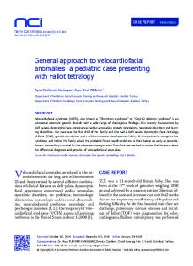
Typically, there are two types of data layout for storing a sequence of encoded integers. Horizontal layout stores n encoded integers according to the original order of the integer sequence, while k-way vertical layout distributes n consecutive integers to k different groups. Furthermore, the number of bits used to encode an integer in binary format is called bit width, while the effective bit width denotes the minimum number of bits to encode an integer in binary. In Figure 1, we present an illustrative example of a 4-way vertical layout. Int1 ~ Int8 denote 8 encoded integers and each four consecutive integers are stored in four different groups respectively.
4
Zhao et al. 0
Int1
32
32 bits
Int2
Int3
Int4
64
Int5
Int6
128
96
Int7
Int8
...
(a) Horizontal layout 32
0
Int1
Int5
...
Int2 Int6
64
...
Int3
96
Int7
...
Int4 Int8
128
...
(b) Vertical layout Fig. 1. Horizontal and vertical data layout.
2.1.3 Evaluation metrics
To evaluate the performance of compression algorithms, there are three widely used metrics, namely decoding speed, encoding speed and compression ratio. Decoding/encoding speed measures the processing rate of integers by an algorithm. The compression ratio is defined as the ratio between the uncompressed size and compressed size, and usually expressed as the average number of bits per encoded integer [Manning et al. 2008, p. 87]. 2.2 Bit-aligned codes
In bit-aligned codes, the bit is the minimum unit to represent an integer. Such codes can be traced back to Golomb coding [Witten et al. 1999, p. 121] and Rice coding [Rice and Plaunt 1971]. Golomb coding encodes an integer by two parts, i.e., the quotient and the remainder. The quotient is unary encoded, and the remainder is binary encoded. The bit width depends on the divisor M, which is commonly set to 0.69 times the average value of all integers. For example, assume that the divisor is 4, we have 14÷4=3 (2), thus 14 will be encoded as “000110”. Rice coding [Rice and Plaunt 1971] further requires M to be a power of two to acceleration the computation. Golomb coding and Rice coding have high compression ratio, but their encoding/decoding speed is low. Elias Gamma [Elias 1975] encodes an original integer x with two parts. The first part is the unary coding of the effective bit width, and the second part is the natural binary representation of x without the leading 1. For example, 14=23+6, thus 14 will be encoded as “0001110” by Elias Gamma. Schlegel et al. [Schlegel et al. 2010] proposed a vectorized version of Elias Gamma coding, called k-Gamma. k-Gamma encodes a sequence of k consecutive integers at a time. It first calculates the effective bit width b of the maximum integer in this sequence, and represents each integer with b bits. Then, the value of b is encoded in unary and the low b bits of each of k integers are encoded in binary. Schlegel et al. adopted the vertical data layout to keep k integers word-aligned, and applied SIMD instructions to vectorize for storing and loading the k integers. As discussed in Section 5, k-Gamma can be viewed as one special variant of our proposed Group-Scheme. 2.3 Byte-aligned codes
Byte-aligned codes represent an integer in bytes. Variable Byte (VB) encoding [Manning et al. 2008, p. 96] uses bytes to represent a non-negative integer, and the most significant bit of a byte is the continuation bit to indicate whether it is the last byte while the remaining bits store the natural binary representation of the integer. Group Variable Byte (GVB) [Dean 2009] aggregates the flag bits of a group of integers into a byte called control byte. When compressing 32-bit integers, a control byte consists of four 2-bit descriptors, where each descriptor represents the number
A General SIMD-based Approach to Accelerating Compression Algorithms
5
of bytes needed for an original integer in binary format (00 for 1 byte, 01, for two bytes, 10 for three bytes and 11 for four bytes). GVB encodes and decodes groups of four integers. There are two ways to code descriptors. If the descriptors are binary coded, the variant is called GVB-Binary. If the descriptors are unary coded, the variant is called GVB-Unary. GVB-Unary includes two variants G8IU and G8CU [Scholer et al. 2002, Stepanov et al. 2011]. Both G8IU and G8CU use 8-byte data areas supported by a 1byte control pattern. In G8IU, all data areas can be independently decoded, but the last few bytes may be wasted (e.g., when storing integers requiring 3 bytes, only 6 out of 8 bytes can be used). Similarly, the last few bits of the control pattern might be unused. In G8CU, we use all bytes, with integers allowed to overlap between two data areas. Stepanov et al. exploited SIMD instructions to accelerate the decoding speed of the three variants of GVB [Stepanov et al. 2011]. On x64 processors, integers packed with GVB can be efficiently decoded using the SSSE3 shuffle instructions: pshufb. We call Stepanov et al.’s implementations with vectorized decoding as SIMD-GVBBinary (or SIMD-GVB), SIMD-G8IU and SIMD-G8CU respectively in this paper. 2.4 Word-aligned codes
In word-aligned codes, we try to encode as many integers as possible into a 32-bit or 64-bit word. Simple-9 [Anh and Moffat 2005; Anh and Moffat 2006] divides a 32-bit codeword into two parts: a 4-bit selector/pattern and a 28-bit encoded data. It sets up 9 different selectors to instruct the encoding of consecutive integers in the 28-bit data. Zhang et al. proposed Simple-16 [Zhang et al. 2008] improving Simple-9 by extending the number of selectors from 9 to 16. Anh et al. [Anh and Moffat 2010] used a 64-bit word (a.k.a. Simple-8b and they refer to 32-bit Simple family as Simple-4b). A codeword consists of a 4-bit selector and a 60-bit data. Previous studies showed that the Simple family has good overall performance with respect to compression/decompression speed and compression ratio [Lemire and Boystov 2015]. 2.5 Frame based codes
A frame refers to a sequence of integers with the same bit width. This category includes PackedBinary [Anh and Moffat 2010], PForDelta [Zukowski 2006; Zhang et al. 2008; Yan et al. 2009], VSEncoding [Silvestri and Venturini 2010] and AFOR [Delbru et al. 2012]. PackedBinary encodes a frame of integers using the same effective bit width of b bits. However, PackedBinary cannot compress well when there are infrequent large integers (called exceptional values). To deal with exceptional values, Zukowski et al. [Zukowski 2006] proposed PFORDelta (PFD), which separates normal integers from exceptional integers. The normal integers are still encoded with the same bit width, but the exceptional integers are kept in a global exception array and processed separately. Zukowski’s implementation does not compress the exceptional values. As a follow-up, Zhang et al. [Zhang et al. 2008] use 8, 16 and 32 bits to store exceptions according to the maximum exceptional values. Yan et al. [Yan et al. 2009] proposed two new variants called NewPFD and OptPFD. They use the same bit width for a frame of 128 integers rather than for all integers. The difference between NewPFD and OptPFD lies in the selection of bit width b. NewPFD determines b by requiring more than 90% of the
6
Zhao et al.
integers can be held in b bits, while OptPFD determines b by optimizing the overall compression ratio. Lemire and Boystov used SIMD instructions to optimize Packed Binary and PForDelta [Lemire and Boystov 2015]. They proposed a novel vectorized algorithm called SIMD-BP128 for fast decompression. They aggregate 128 successive integers as a frame and use vertical layout to pack them with a unified bit width b for the frame. For better compression ratios, they further proposed another new vectorized variant called SIMD-FastPFor, in which they design effective techniques to store the exceptional values. Packed Binary and PFORDelta adopt a fixed frame length (i.e., the number of integers in a frame) in contrast to approaches using varying frame lengths to improve compression ratio. Silvestri et al. proposed VSEncoding [Silvestri and Venturini 2010], which uses a dynamic programming approach to partition a list of integers into frames. Frame lengths are chosen from the set {1, 2, 4, 8, 12, 16, 32, 64}. Similarly, Delbru et al. proposed AFOR (Adaptive Frame of Reference) [Delbru et al. 2012], which uses only three different frame sizes: {8, 16, 32}. 3. A GENERAL SIMD-BASED COMPRESSION APPROACH
In this section, we present a general compression approach designed to incorporate SIMD-based vectorization in integer compression routines. We are motivated by pioneering studies on SIMD-based compression algorithms [Schlegel et al. 2010; Stepanov et al. 2011; Lemire and Boystov 2015]. We borrow and generalize the core ideas of previous SIMD-based algorithms. For convenience, we first summarize the terminology used throughout the paper in Table I. Table I. Our terminology. Terminology Snip Control pattern
Explanation Each primitive unary or binary codeword is referred to as a snip. We distinguish between two types of snips: control patterns and data snips. A control pattern is a snip that describes how several integers are packed.
Control area
The data space storing several control patterns.
Vector
A vector denotes 128-bit data.
Component
A vector is further divided into four 32-bit data components.
Data area
The data space containing the data snips where integers are packed.
Frame
A frame denotes a sequence of integers.
Quadruple
A quadruple denotes four consecutive integers.
Scalar Vectorized
Scalar algorithms use conventional instructions operating on single words. Vectorized algorithms rely on vector instructions operating on several words at once.
3.1 Encoding Formats
The storage layout of a compression algorithm often consists of control patterns and data snips. Data snips represent the encoded integers in binary format, while control patterns code the auxiliary information necessary to interpret the data snips. Many compression algorithms such as VB [Scholer et al. 2002] and Rice [Rice and Plaunt
A General SIMD-based Approach to Accelerating Compression Algorithms
7
1971] interleave the control and data snips in a continuous stream. For example, in Simple-9, each 32-bit word contains a control pattern (4 bits) followed by a data snip (28 bits). Yet previous authors have found it convenient to separate control patterns from data snips in distinct space when designing SIMD compression algorithms [Schlegel et al. 2010; Lemire and Boystov 2015]. We adopt this idea. Thus, in creating a vectorized version of a scalar algorithm, we store continuously the data snips in the data area. Similarly, we regroup the control patterns in the control area separately. Moreover, we pack the data snips using a 4-way vertical data organization. We consider an existing integer compression algorithm where a control pattern describes a sequence of N consecutive integers. In our approach, we use this same control pattern to describe a sequence of 4N consecutive integers. I.e., the control pattern describes N integer quadruples. Each four integers in a quadruple are encoded in the same way, and distributed into the four 32-bit data components of a 128-bit data vector. As much as possible, our encoding and decoding routines are just a vectorized version of the original scalar routines: if a control pattern specifies that 32 integers are packed using a bit width of 10, then we would pack 128 integers using the same bit width (10). Though simple, this approach is effective. For algorithms with exceptional values (e.g., PForDelta), it is infeasible to directly apply our strategy because we have exceptions in addition to control patterns and data snips. However, it is not difficult to extend our approach to include exceptions stored in a separate location. 3.2 SIMD-based Encoding and Decoding
SIMD (Single Instruction, Multiple Data) instructions are widely supported by modern processors. In particular, our SIMD-based algorithms focus on the SSE instructions available on all recent Intel processors [Intel 2010]. These instructions operate on 128-bit registers (called XMM registers) making it possible to process four 32-bit integers simultaneously. The main SSE instructions used in our algorithms are: MOVDQA dst src: Copy from 128-bit data source src to 128-bit dst. src and dst must be 16-byte aligned, and both cannot be a memory address at the same time (it requires at least one register). MOVDQU dst src: Same as MOVDQA except that src and dst are allowed to be 16-byte unaligned. PSRLDQ/PSLLDQ xmm1 imm8/xmm2: Regard xmm1 as an array of four 32-bit integers, and logically shift each integer right/left according the value of immediate imm8 or xmm2 register. PAND/POR xmm1 xmm2: execute AND/OR operation on the two 128-bit XMM registers.
It has been noted that a 128-bit data vector can be loaded into 128-bit XMM register, which is particularly useful for the vectorization of the scalar compression algorithms. As discussed in Section 3.1, each four consecutive integers in a quadruple are distributed into four data components by adopting the 4-way vertical layout. More importantly, the four integers in a quadruple are encoded in the same way (e.g., with the same bit width), which makes it feasible to process four 32-bit data components simultaneously with SIMD instructions. For encoding and decoding integers, we are able to vectorize the shift and mask operations for each four integers with SIMD in-
8
Zhao et al.
structions, which yields a 75% reduction in the number of executed operations. (See Section 4.4.) 3.3 Overall organization of the following sections
In Table II, we categorize commonly used (non-SIMD) compression algorithms into four categories. We instantiate the proposed compression approach on several scalar compression algorithms from these four categories. The roadmap of the following sections is listed as follows: – Word-aligned: In Section 4, we propose the Group-Simple algorithm, which extends the Simple-9 algorithm. – Bit/Byte-aligned: In Section 5, we propose the Group-Scheme family, which originates from the ideas of Elias Gamma and Group Variable Byte algorithms. – Frame based: In Section 6, we propose the Group-AFOR and Group-PFD based on AFOR and PForDelta respectively. Table II. Algorithm categorization with the corresponding instantiations in our approach. We mark the instantiated algorithms in bold and present specific modification points to fit into the approach. Algorithm category Bit-aligned
Byte-aligned
Scalar algorithms
Instantiations in our approach
Specific modification
Golomb Rice Elias Gamma k-Gamma Variable Byte Group Variable Byte
Group-Scheme
Incorporate different compression granularities and length descriptors into the encoding format.
Word-aligned
Simple-9 Simple-16 Simple-8b
Group-Simple
Frame based
PackedBinary PForDelta AFOR FastPFor
BP128 Group-PFor Group-AFOR
Provide ten optional controlling patterns and the effective bit width can be up to 32-bits (Simple only supports a maximum bit width of 28 bits). Apply split selection (AFOR) or bit width selection (Packed Binary) on a quarter of the original integer array.
4. GROUP-SIMPLE ALGORITHM
In this section, we extend the well-known Simple algorithm to a novel algorithm called Group-Simple, which uses the general approach in Section 4. Similar to Simple-9/16, Group-Simple still uses four bits to represent a control pattern. The difference is that a control pattern in Group-Simple instructs the compression of 128-bit data rather than 28-bit data. The encoding/decoding operation of a 128-bit data vector can be potentially optimized by SIMD instructions. 4.1 Encoding Format and Storage Layout
In this part, we first introduce the storage layout and optional patterns in GroupSimple algorithm. 4.1.1 Storage Layout
In Simple-9/16 algorithms, a 32-bit codeword is divided into two parts: a 4-bit control pattern and 28-bit encoded data. Each control pattern corresponds to a 128-bit data vector, which is further divided into four 32-bit data components. In Figure 2, we present a schematic diagram for the storage layout in GroupSimple. The major difference between Group-Simple and Simple-9/16 is that control
A General SIMD-based Approach to Accelerating Compression Algorithms
9
patterns and encoded data are stored separately in physical space to ease vectorization: the control area stores all control patterns, and the data area stores all data components. The data area adopts the 4-way vertical storage layout. Pattern Area
0
Data Area
0
4
Selector
s1
8
s2
32
...
128
Component Component
160
256
...
Component Component
Data Vector
Data Vector
Fig. 2. Overall storage layout in Group-Simple.
4.1.2 Control Patterns
In Group-Simple, we use four bits to represent a control pattern. Each control pattern corresponds to a triplet (SEL, NUM, BW), where SEL denotes the selector identifier for the optional patterns, NUM denotes the number of integers encoded in a 32bit data component, and BW denotes the bit width of an integer in the data component. Table III shows the ten optional patterns in Group-Simple. With the increase of the selector identifier (SEL), the number of encoded integers (NUM) in a data component decreases, and the bit width (BW) of each encoded integer increases. One advantage of Group-Simple over Simple-9/16 is that the maximum bit width for an encoded integer can be up to 32 bits, which is important for compressing document collections with large docIDs. Table III. Optional patterns in Group-Simple. SEL NUM BW
0 32 1
1 16 2
2 10 3
3 8 4
4 6 5
5 5 6
6 4 8
7 3 10
8 2 16
9 1 32
4.2 Encoding Procedure
Our encoding procedure is similar to that of the original Simple-9 algorithm. We determine the control patterns, and store them along the corresponding data snips. In contrast with Simple-9, we store the control patterns and data snips in distinct locations. However our encoding process in preceded by the generation of a temporary buffer called quad max array that stores the maxima of quadruples. In what follows, we review the three key points of the encoding procedure in details. • Generation of the quad max array. Group-Simple adopts the 4-way vertical layout, and each four integers from four consecutive components of a vector share the same control pattern. It indicates that each four integers in a quadruple share the same bit width, which is determined by the maximum integer in the quadruple. We refer to this integer as a quad max integer. The quad max array stores all the quad max integers. Formally, the quad max numbers are generated taking of the maximum of each four integers in the input array as follows: max 4∗ , 4∗ 1, 4∗ 2, 4∗ 3 , where input denotes the input array and i is the index variable. The quad max array is built and maintained in RAM, and released once we have generated the control patterns for all integers.
10
•
Zhao et al.
Pattern selection algorithm. Similar to Simple-9/16, a naïve way to select the control patterns is to scan all the integers in a sequence. Here we propose a pattern selection algorithm based on the quad max array, which only needs to process a quarter of the original integers. We present the pattern selection algorithm in Algorithm 1. It requires two input parameters (i1) MaxArr, the quad max array and (i2) L, the length of MaxArr. The algorithm returns with (o1) ModeArr, the array of generated selectors and (o2) TotalModeNum, the length of ModeArr. At each iteration, it examines each of the ten optional patterns in an ascending order of the selector identifiers (SEL) and tries to find a pattern to fit the remaining quad max integers as many as possible. With the increase of the selector identifiers, the number of integers in a data vector decreases and the bit width increases. More specially, Line 1~4 are the initialization steps for variables, Line 6~16 are the inner loop for pattern selection, and Line 17~19 are the update steps for the variables. It is worth explaining the inner for loop for pattern selector in more details. When an integer has greater effective bit width than the current selector (BW), we consider the next pattern with a larger bit width. The loop in Line 14 ends when (1) the number of integers reaches the limit of the current selector, i.e., NUM ; (2) we have reached the end of MaxArr. We use the shift operation to obtain the largest number with an effective bit width of b bits, i.e., the variable mask.
ALGORITHM 1. The pattern selection algorithm for Group-Simple. Input: MaxArr, the quad max array of integers with bit widths no larger than 32 L, the length of MaxArr (NUMi, BWi), the optional patterns in Group-Simple in Table III
Output:
ModeArr, the array of generated selectors TotalModeNum, the length of ModeArr 1.Initialize ModeArr to be an empty array 2. TotalModeNum←0 3. l ← L /* get a value copy of L */ 4. j ← 0, k ← 0 5. while l > 0 do 6. for i = 0 to 9 do 7. (n, b) ← (NUMi, BWi) 8. mask ← Power(2,b) - 1 9. pos ← 0 10. while pos < min(n,l) AND MaxArr[j+pos] ≤ mask pos ← pos + 1 11. 12. end 13. if pos = n OR pos = l then exit from for loop 14. 15. end 16. end l ← l – pos, j ← j + pos 17. 18. ModeArr[k] ← i, k ← k + 1 19. TotalModeNum ← TotalModeNum + 1; 20. end
A General SIMD-based Approach to Accelerating Compression Algorithms
11
Packing original integers into vectors. After pattern selection, we examine how to pack a sequence of integers into vectors with the generated control patterns. To encode a single data vector, the algorithm loops NUM times. Each time it uses the shift and mask operations to store four integers respectively into four 32bit data components, where NUM is the number of compressed integers in a component. The algorithm will encode 4NUM integers into a 128-bit data vector.
•
Figure 3 presents an illustrative example for the encoding of a sequence of twenty 32-bit integers by using Group-Simple. The quad max integers are marked in bold. To hold the largest integer 64, we need at least a bit width of 6 bits. Therefore, the 5th selector in Table III is selected, which indicates that 5 integers are packed in a 32-bit data component and each encoded integer occupies 6 bits. 0 32 bits 32
63
31
0
44
4
48
17
8
23
42
37
52
11
3
8
14
15
51
25
12
18
24 30 32
23
11
15
31 48 42
3
51
0
63
Pattern Selection
0
6
12
18
24 30
63
48
52
14
51
32 bits
6
4
32
Data Packing
2
0
17 37
8
25
44
8
14
2
52
32 bits
Fig. 3. An example to illustrate the encoding procedure of Group-Simple.
4.3 The Decoding Procedure
The key step in decompression is to decode a 128-bit data vector, which contains 4NUM encoded integers (NUM is the number of integers in a data component corresponding to the selector of the current data vector). In this procedure, the algorithm loops NUM times, and in each loop we use the shift and mask operations to decode four integers respectively from four data components. We present the decoding procedure of Group-Simple as follows: 1)
Read the start offset of the data area from the head pointer of SrcArr, and locate the start position of the control area, denoted by ModePos. The start position of the data area is denoted as DataPos.
2)
Read four bits from ModePos and obtain the current selector.
3)
Decode a 128-bit data vector at DataPos with the current selector.
4)
Move ModePos and DataPos forward by 4 bits and 128 bits respectively. If ModePos does not reach the end, go to step 2.
4.4 SIMD-based Implementation and Optimization Techniques
The SIMD-based implementation of Group-Simple is called as SIMD-Group-Simple. Once we have transformed the original Simple layout into the format in Figure 2, it is relatively easy to apply SIMD instructions to implement SIMD-Group-Simple: we can vectorize the shift and mask operations and process four integers from four data components simultaneously by using SIMD instructions. We review two optimization techniques that we put into practice: • In the encoding procedure, the generation of the quad max array involves conditional statements for value comparison (i.e., identify the maximum value from four integers). The function of the quad max array is to determine the suitable bit
12
Zhao et al.
widths for encoded integers. To reduce conditional statements, we do not need to identify the exact quad max integers but the pseudo quad max integers instead. Following Lemire and Boystov, we use the logical OR operations to generate pseudo quad max integers, which may not be equal to the real quad max integer but have the same effective bit width [Lemire and Boystov 2015]. • When decoding a single data vector, since both SEL and NUM have a fixed set of optional values, we use a SWITCH-CASE statement with one case for each possible value of the pair (SEL, NUM). For each case we use an optimized routine. These techniques yield a 20% and 50% improvement at the encoding and decoding speed respectively. 5. THE GROUP-SCHEME COMPRESSION ALGORITHM FAMILY
In the previous section, we have presented the instantiation of Simple algorithm with the proposed approach. Inspired by Elias Gamma [Elias 1975] and Group Variable Byte (GVB) [Dean 2009], we present another family of compression algorithms called Group-Scheme. 5.1 Variants in Group-Scheme family
To better describe the variants in Group-Scheme, we first introduce two terms: compression granularity and length descriptor. - Compression granularity (CG) is defined as the minimum unit operated on (or allocated) by a compression algorithm. For example, the compression granularity of Elias Gamma and k-Gamma coding is 1 bit, while the compression granularity of Variable Byte encoding is a byte, i.e., 8 bits. - Length descriptor (LD) is defined as the minimal number of units necessary to represent (or encode) an integer. For instance, given a compression granularity of 2 bits, the length descriptor of an integer 45810 (1110010102) is 5 because we need five 2-bit compression units to hold nine bits. We need to represent the length descriptor itself either in binary or unary: e.g., 5 can be represented as “101” in binary or “11110” in unary. We set up four compression granularities for Group-Scheme: 1, 2, 4 and 8 bits. By combining optional values of compression granularities and the two storage technique for length descriptors (binary and unary), the Group-Scheme family contains eight variants in total as summarized in Table IV. Table IV. Length descriptors for algorithms in the Group-Scheme family. Compression Granularity (CG)
Length Descriptor (LD)
1 bit
2 bits
4 bits
8 bits
Binary Unary
5 1~32
4 1~16
3 1~8
2 1~4
When the compression granularity is set to one bit and the length descriptor adopts the complete unary coding, Group-Scheme becomes k-Gamma [Schlegel et al. 2010]. In this sense, Group Scheme is a generalization of k-Gamma. 5.2 Encoding formats and encoding/decoding procedure 5.2.1 Encoding formats
Group-Scheme follows the format of data area described in Section 3, and the major difference lies in the control area, which is composed of several encoded length de-
A General SIMD-based Approach to Accelerating Compression Algorithms
13
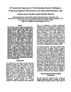
scriptors acting as a control pattern. Based on the coding type (binary/unary), GroupScheme stores length descriptors (LD) in two ways: (a) Unary LD: There are two methods to store unary LDs. If a unary length descriptor can be stored across bytes, we call it Complete Unary1 or CU for short. If length descriptors cannot be stored across bytes, we call it Incomplete Unary or IU. Note that we do not consider the 1-bit and 2-bit CG for incomplete unary LD, since the maximum number of bits needed for a single LD will exceed eight bits with 1-bit and 2-bit CG. Figure 4 shows the examples of IU and CU for the 4-bit and 8-bit compression granularities. Figure 4 illustrates two observations. First, for length descriptors, IU wastes some bits to be byte aligned, while CU does not require byte alignment. Second, for data areas, both IU and CU can store values across words.
Fig. 4. An example to compare incomplete unary coding (IU) and complete unary coding (CU). Note that there is one data vector in (a) and (b) and two data vectors in (c) and (d).
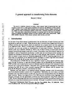
(b) Binary LD: Figure 5 shows four different encoding formats for control area with binary length descriptors. The bit width of a LD is log 32/CG # 5 − log CG# .We adopt aligned storage for length descriptors at the cost of some wasted bits. The aligned storage is mainly for accelerating and simplifying the encoding/decoding procedure of length descriptors. The alignment depends on the CG. For example, 1-bit CG requires double-byte alignment, while 4-bit CG requires byte alignment. Although binary LDs are word aligned, the data area can store values across words.
1
Following Stepanov et al., we use the terminologies of complete unary and incomplete unary to discriminate between cross-byte storage and byte-aligned storage [Stepanov et al. 2011].
14
Zhao et al. 0
16 bits
0
8 bits
0
8 bits
LD
LD
LD
LD
LD
LD
5
5
5
4
4
3
(b) 2-bit CG
(a) 1-bit CG
LD 1
3
0
8 bits
LD LD LD LD 1
(c) 4-bit CG
2
2
2
2
(d) 8-bit CG
Fig. 5. The corresponding formats of Group-Scheme with different binary length descriptors. The compression granularity and length descriptor are shortened as CG and LD respectively.
5.2.2 Encoding procedure
We first find the maximum integer quadmax of a quadruple, and then we calculate the length descriptor as follows ValueOfLD
. /01 . /01
1 #/234 − 1, 5
1 #/234, :
67 89
67 89
(1)
The length descriptor (either unary or binary) is stored in the control area. We use the shift and mask operations to encode four integers by taking the low 1 /23# ; 23 bits of an integer. Furthermore, these four encoded log integers are stored into four different 32-bit data components of a data vector respectively. We update the pointer for the data component and the bit offset within the current component. For an across-word integer, we split it into two parts from high to low by using right-shift and mask operations. The first part is stored in the current data vector and the second one would be stored in the next data vector. The steps are repeated until all the integers are encoded. 5.2.3 Decoding procedure
We first read a length descriptor from the control area and calculate the bit width BW for the encoded integers of data area, where 5