Lecture Notes on Software Engineering, Vol. 1, No. 1, February 2013
A MDA Approach for Database Modeling AndréRosa, Italine Gonçalves, and Carlos E. Pantoja
shows the proposed MDA approach; section IV presents a simplified example of the approach; section V presents some related works and section VI concludes the paper.
Abstract—This paper proposes an approach for database modeling based on MDA, which aims to facilitate the database designer to choose between different conceptual modeling notations to use and automate the entire process, from conceptual modeling to code generation DDL, that will be compatible with ANSI SQL 92/99/2003 standards for implementation different DBMS. A meta-model that contains the characteristics necessary to be adherent to different notations as ER, IDEF1X and Crow’s Foot will be proposed and the transformation of the conceptual model for the DDL code will be made using the MOFM2T language, provided by the OMG. A tool for the Eclipse development environment was constructed based on the approach; the meta-model was built using EMF and the transformations rules that generate SQL code was implemented in MOFM2T using Acceleo. It was instantiated a conceptual model based in ER notation that represents the factory organization database. After the transformations, we obtained the corresponding DDL code modeling instantiated which can be implemented in a DBMS that is standards compliant with SQL 92/99/2003.
II. DATABASE CONCEPTUAL MODELING This section describes some of the database modeling notations that is adherent to the metamodel proposed, the Model-Driven Architecture, the Eclipse Modeling Framework and the MOF Model to Text Transformation Language . A. Modeling Notations The data modeling consists in determine the database structure using a textual or graphical notation for the desired level of abstraction. For the database project there are several techniques used to construct this model. The Entity-Relationship Model (ER) [2] uses a diagrammatic technique with entities and relationship based in three different notations to model the world's information: Network Model, Set Theory [3] and Relational Model [4]. The Crows Foot notation is often used in data modeling process. In this notation the entities are represented by squares containing its name, the relations between them are represented by lines which link each other and the cardinalities are represented by distinct forms located in the ends of the lines, being a filled circle the symbol of that one of entities in the relation has optional participation. The distinct forms previously mentioned can be used together with the other ways of cardinality indication. Two vertical traits are the symbols of the minimum and maximum limit of the entity participation in a relation with only an element and a unlimited definition for the participation of an element in determinate entity set is represented by a symbol that remember a crow’s foot, containing three lines starting of a vertical line for the other entity being one horizontally straight, one inclined for upper edge of board and the other for bottom edge [5]. The IDEF1X notation is a conceptual modeling notation based in Entity-Relationship model and was used as North American modeling standard by NIST [6]. The entities in this notation are represented by a rectangle containing a horizontal division line being written above of this line the attributes which will be the primary keys of the entity and below it the other attributes which can be used as foreign key if necessary and the foreign key is distinct by the symbol (FK) in the front of the respective attribute and the alternative keys are described by the symbol (AK) in front of it. The entities can be dependents or independents, in the first case the form that represent this entity has a rounded shape and its primary key is formed by the key of other entity, being an example of this case, the situations that occur the
Index Terms—Database modeling, model-driven architecture, model-to-text transformation.
I. INTRODUCTION A database project is composed by three distinct phases: the conceptual modeling, the logical and physical project [1]. The transition between them, until the effective implementation of a database into a Database System Manager (DBSM) is a process that demands time and effort by the modeler. There are some tools in the database literature that is responsible for the conceptual modeling like DBDesigner for MySQL, Visual DataBase Tool for MS SQL Server and DBExplorer, which is versatile but is not free. However, those tools are directly for a specific DBSM and, in some cases, they use their own or modified modeling language. Those bonds between the tools and the DBSM limit the model development process because the modeler is forced to use the tool's modeling language. This paper proposes a Model-Driven Architecture (MDA) approach for database conceptual modeling that provides a set of templates in Model To Text (M2T) to generate ANSI SQL 92/99/03 DDL code. A meta-model that will be able to instantiate the existing database modeling languages will be proposed. A tool for database modeling will be developed using the Eclipse Modeling Framework (EMF) and the text artifacts generator named Acceleo. This paper is structured as follows: section II describes some basic concepts; section III
Manuscript received October 15, 2012; revised November 7, 2012. The authors are with the CEFET/RJ - Uned Nova Friburgo Brazil. (e-mail: mail:
[email protected] ).
DOI: 10.7763/LNSE.2013.V1.6
26
Lecture Notes on Software Engineering, Vol. 1, No. 1, February 2013
the Model, is responsible for the database modeling models that will be instantiated. A model is composed by Database elements.
specialization of a generic entity in specific entities and in the second case the forms that represent the entities has the normal form of rectangle. The relationships between entities are represented by same lines, by a verb or verb phrase which links one entity to another containing in its ends some formats used for differentiate the cardinality that limits the participation of each element of the entity set in the relation. A filled circle represents the participation of many elements of the entity set near it, a lozenge represents an optional participation in the relation and the absence of symbols represents the participation of an only element [7]. The Min-Max notation refers to way of represent the cardinality used in combination with ER to determine the minimum and maximum of times that the entity participates of the relationship. In this notation the cardinalities are represented by pairs of whole numbers near the representation of the entity that the element belongs. The cardinality which is related to minimum limitation is on the left side of the notation and the cardinality which is related to maximum limitation is on the right such as (1, N), (1, 1) [8].
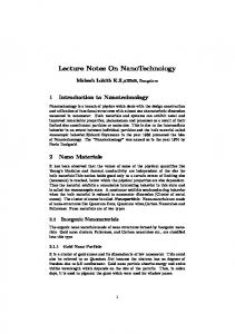
Fig. 1. The proposed approach.
The Database element is responsible for the database that will be generated by the modeling language. A Database is composed of at least one Entity element to avoid an empty database. The Entity element represents an entity that has some information to be persisted by the database. An Entity element is composed of Field elements that represent the properties of respective modeled entity. It also has a self-relationship called subGroupOf that is responsible for the specialization construction and a group of Check elements to satisfy the SQL check command. A Field element has relations to Primary Key and Foreign Key elements to be implemented in the physical layer and also has the SQL constraints elements TextLimit, Integrity, DefaultValue and NumericLimit. The interaction between entities in a database modeling language is represented by their relationships with each other. Thus, a Relationship element was created to satisfy this condition. This element is related with Entity elements to determine whose are in that relationship. A Relationship has a Cardinality, that can be 1:1, 1:N and N:N. For the N:N cardinality, an associative table is generated from the relationship and has Field, Foreign Key and Primary Key elements like an Entity element. The proposed metamodel can be seen in Fig. 2. After the metamodel was instantiated, a set of Model To Text transformations will be executed to provide ANSI SQL codification. A text document with the SQL code will be generated. The template ModelToText will initiate the transformation process getting all the Database elements into a model element and calling the toDatabase template. The toDatabase template will call the toEntity and crtAsTbl templates. The toEntity template will receive a set of Entity elements and will transform them into a create table sentence. The crtAsTbl template will create the tables for the associative tables where the cardinality is N:N and the isAssociative attribute is true. The templates modelToText, toEntity and crtAsTbl are shown as follows:
B. Model-Driven Architecture The MDA allows the developers to build models of the project without the knowledge of others application models, afterwards combining them to create the application. The use of MDA technique allows that the application are platform independent increasing the project's interoperability and facilitating its maintainability. The Object Management Group (OMG) is the responsible for the standardization of MDA [9]. C. Eclipse Modeling Framework The EMF is a framework integrated with Eclipse Development Environment, which generates tools based on structured models for code generation. The meta-models are created using the EMF Ecore Tool, which generates a XMI file based on the Ecore constructs. The input tool for the metamodel receives a XML file based on the XMI structure generated earlier. The EMF also includes a text artifact generator using templates based on MOFM2T transformation language[10]. D. MOF Model To Text Transformation Language The MOF Model To Text (M2T) is an OMG approach to transform models to text artifacts. This work uses the Acceleo tool that was implemented based on M2T and it was projected to allow source code generation from MOF[11].
III. THE MDA APPROACH This section proposes a MDA approach for database modeling teaching (Fig. 1.) that generates ANSI SQL code. A generic metamodel for some existing database modeling languages is proposed and it will work as a Platform Independent Model. Afterwards a set of M2T templates will generate the ANSI SQL 92/99/03 DDL code. The metamodel was defined observing the existing database modeling languages, e.g. ER, and some constructions from SQL. The first element of the metamodel,
[template public ModelToText(aModel : Model)] [comment @main/] [file (aModel.name+'.txt', false, 'UTF-8')] [toDataBase(aModel.isFormedOf)/] [/file] 27
Lecture Notes on Software Engineering, Vol. 1, No. 1, February 2013
[/template]
Fig. 2. The proposed metamodel
[template public toEntity(aEnt : Set(Entity))] [for (iEnt : Entity | aEnt)] create table '[iEnt.name/]'( [toField(iEnt.isComposed)/] [printPrimary(iEnt.hasPrimaryKey)/] [printForeign(iEnt.hasForeignKey, aEnt)/] [if (iEnt.hasChecknull)] [printCheck(iEnt.hasCheck)/] [/if]); [/for] [/template]
follows: [template public toField(aFields : Set(Field))] [for ( iField : Field | aFields ) ] [iField.name/] [iField.type/] [if (iField.hasNumericLimit null)] [printNumericLimit(iField.hasNumericLimit)/] [/if] [if (iField.hasTextLimit null)] [prtTextLimit(iField.hasTextLimit)/] [/if] [prtIntegrity(iField.hasIntegrity)/] [if (iField.hasDefaultValue null)] [prtDefVal(iField.hasDefaultValue)/] [/if], [/for] [/template]
[template crtAsTbl(aRel : Set(Relationship))] [for (iRel : Relationship | aRel)] [if (iRel.isAssociative = true)] create table '[iRel.name/]' ( [prtRelationCharacteristics(iRel.related)/] [prtRelFields(iRel)/] [prtFieldsN_N(iRel, iRel.related)/] ) [/if] [/for] [/template] The toEntity template calls other templates: toField, prtPrimary, prtForeign and prtCheck. The toField template receives a set of Fields elements and will generate a column for each metamodel field. Afterwards the constraints templates printNumericLimit, printTextLimit, printIntegrity and printDefaultValue are called. The templates toField, prtTextLimit, prtIntegrity and prtDefVal are shown as
[template public prtTextLimit(aTxt: TextLimit)] ([aTxt.size/]) [/template] [template public prtIntegrity(aInt : Integrity)] [if(aInt.not_null=true)]not null[/if] [if ( aInt.unique=true)] unique[/if] [/template] [template public prtDefVal(aDef : DefaultValue)] Default '[aDef.value/]' [/template] The prtPri template receives a set of PrimaryKey elements that was modeled to identify uniquely a table's row and 28
Lecture Notes on Software Engineering, Vol. 1, No. 1, February 2013
The Fig. 3. is an example of an ERM that will be instantiated and after transformed in code by the transformation rules. The entities that will be represented on database are Department, Employee and Project. Accordingly to the example, each element of Employee is associated with an only element of Department by the relation Dept-Emp and can be associated to a lot of elements of Project by the relation Proj-Work and each element of Project is associated an only element of Employee in the relation Proj-Manager.
generates the SQL code. The prtForeign template receives a set of ForeignKey elements and generates the foreign key code that references the property's table. The printCheck template generates a validation for a specific column that was previously modeled. The templates printPrimary, printForeign and prtCheck are shown as follows: [template public prtPri(aPri:Set(PrimaryKey))] Primary Key( [for (iP: PrimaryKey | aPri) separator (', ')] [iP.isPrimary.name/] [/for]) [/template] [template public prtForeign(aF : Set(ForeignKey) ,aEnt : Set(Entity))] [for (iFor : ForeignKey | aF) separator (', ')] [if (iFor.name null)] Constraint [iFor.name/] Foreign Key ([iFor.isForeign.name/]) [printReferences(aEnt)/] [/if] [/for] [/template]
Fig. 3. An Entity-Relationship Model example [2].
The Fig. 4. represents the example model instantiated that was instantiated in the tool. The model is instantiated using a XML document and it is showed by all the elements graphically represented in a hierarchical structure. After being subjected by transformation rules, the model will generate DDL source code in the ANSI SQL 92/99/03 standards containing the description of the structure of database tables that can be viewed in supported Database Management Systems. The generated SQL codes are shown as follows:
[template public prtCheck (aChk : Set(Check))] [for (iChk : Check | aChk)] Constraint [iChk.name/]CHECK([iChk.condition/]) [/for] [/template] The prtRelationCharacteristics template will be called to generate the columns of an associative table. This template calls the prtFieldsN-N and prtRelFields to generate the key columns of a table and calls the prtRelFields that verifies if exists any relation's property to be generated.
create table Departament( cod_departament int (7) not null unique, name varchar (50), Primary Key(cod\_departament) );
[template public prtRelationCharacteristics (aEnt : Set(Entity))] [for (iEnt : Entity | aEnt)] [printCandidateKeyFieldsN_N(iEnt)/] [/for] [/template]
create table Employee( cod_employee int (7) not null unique, name varchar (50) not null, genero varchar (1) not null Default 'M', Primary Key(cod_employee), Constraint fk_departament Foreign Key (cod_departament) References Departament (cod_departament), Constraint chk_employee CHECK (cod_employee > 0) );
[template public prtFieldsN_N(aEnt : Entity)] [for (iPri : PrimaryKey | aEnt.hasPrimaryKey)] [toField(iPri.isPrimary)/] [/for] [/template] [template prtRelFields(aRel : Relationship)] [if (aRel.isMappingnull)] [toField(aRel.isMapping)/] [/if] [/template]
create table Project( cod_project int (7) not null unique name int (50) not null Primary Key(cod_project) Constraint fk_employee Foreign Key (cod_employee) References Employee (cod_departament) );
IV. AN EXAMPLE The tool was constructed in Eclipse development platform using EMF to create the metamodel that is used in the MDA approach. The Acceleo was used to allow the implementation of transformation rules and generate SQL code in EMF. 29
Lecture Notes on Software Engineering, Vol. 1, No. 1, February 2013
create table proj-work ( cod_employee int (7) not null unique, cod_project int (7) not null unique, Primary Key(cod_employee,cod_project), Constraint fk_employee Foreign Key (pk_employee) References Employee (cod_employee), Constraint fk_project Foreign Key (pk_project) References Employee (cod_project) );
VI. CONCLUSION This paper focus was to provide the users the possibility of use different notations of conceptual modeling using the MDA approach. In addition, it offers a tool that is more integrated with different Database Management Systems, contributing to the versatility over the development and increase the re-usability of the models. In future works will be developed a graphical environment for the adherents modeling notations using Graphical Modeling Framework (GMF) and also will be incorporated into the tool an information retrieval technology to percept the requirements of the system and instantiate automatically the metamodel proposed in this paper. Afterwards the graphical model could be self-generated. REFERENCES [1]
C. Heuser, Projeto de Banco de Dados, 6th ed. Rio grande do Sul, Brazil: Bookman, 2009, vol. 2, pp. 34-64. [2] P. P. Chen, “The entity-relationship model –toward a unified view of data,” ACM Transaction On database Systems, vol. 1, pp. 9-36, 1976. [3] P. Halmos, Naï ve Set Theory - Undergraduate Texts in Mathematic, 1st ed. New York: Springer-Verlag, 1974, ch 1. [4] E. F. Codd, “A relational model of data for large shared data banks,” Communications of the ACM, vol. 13, no. 6, pp. 377-387, 1970. [5] D. Hay, “A comparison of data modeling techniques,” Essential Strategies, 1999. [6] NIST, Federal information processing standards publication 184: Integration definition for information modeling (IDEF1X), Processing Standards Publication, 1993. [7] T. Bruce, Designing quality databases with IDEF1X information model, 1st ed. New York: Dorset House Pub, 1992, ch1. [8] I. Limited, Introduction To Database Systems, 1st ed. India: Pearson Education, 2010, vol. 1. [9] S. J. Mellor, K. Scott, A. Uhl, and D. Weise, MDA Destilada: Princí pios de Arquitetura Orientada por Modelos, São Paulo, Brazil: Ciência Moderna Ltda, 2005, vol. 3, pp. 15-51. [10] D. Steinberg, F. Budinsky, E. Merks, and M. Paternostro, Emf: Eclipse Modeling Framework. US: Pearson Education, 2008, pp. 28-144. [11] OMG. MOF-Model to text transformation language (MOFM2T), 1.0. [Online]. Available: http://www.omg.org/spec/MOFM2T/1.0, 2008.
Fig. 4. Instantiated model.
V. RELATED WORK
André de Souza Rosa is an Industrial Computing Student at the Federal Center of Technological Education Celso Suckow da Fonseca (CEFET / RJ) Uned Nova Friburgo. He was born in Nova Friburgo, Rio de Janeiro, Brazil in March 24, 1986.
There are some tools related to database modeling which are used because of automation and practicality offered to assist the development process, however some of these tools are paid and bonded to specific Database Management Systems (DBMS). There is also the fact that some of them have their own modeling notation demanding more time in the development and limiting the developer. The DBDesigner is a non-paid software but is limited by the fact of being exclusive to MySQL and has a particular modeling notation. The Oracle Designer also has a specific notation with its own particularities and is destined for the Oracle DBMS. The CA Erwin is compatible with the most of major Database Management System on the market like MySQL, ODBC, Oracle, Progress, SQL Server and use graphic notation the IDEF1X but it paid. The proposed MDA approach in this paper aims to achieve the highest possible level of reuse using a versatile metamodel in its core which can adapt to various modeling notations. The data output is generated by transformation rules, described in MOF M2T, in standard ANSI SQL carrying great potential for various different DBMSs.
Italine da Silva Gonçalves is an Industrial Computing Student at the Federal Center of Technological Education Celso Suckow da Fonseca (CEFET / RJ) Uned Nova Friburgo and is also a Computer Systems Student at Federal Fluminense University. She was born in Teresópolis, Rio de Janeiro, Brazil, in April 7, 1994.
Carlos Eduardo Pantoja is graduated in Information Technology at the University Center of the City in 2004 and Bachelor in Industrial Administration at the Federal Center of Technological Education Celso Suckow da Fonseca (CEFET / RJ) in 2011. Master Student in Computer Systems by the Military Institute of Engineering (IME). He is currently a professor at the Federal Center for Technological Education Celso Suckow da Fonseca (CEFET / RJ) and his researches are concentrated in the area of multi-agent systems and artificial intelligence.
30