A Method for Evolving Networks by Introducing New Virtual Node/link Types using Node Plug-ins Yasusi Kanada Central Research Laboratory, Hitachi, Ltd. Totsuka-ku Yoshida-cho 292, Yokohama 244-0817, Japan
[email protected] Abstract—Network virtualization introduces two concepts: slice (i.e., virtual network), which consists of virtual nodes and links, and slice developer, which is the third role in networks. Slice developers can introduce new network services by using slices. A method for introducing new types of virtual nodes and links for new services into the slice-definition language and the virtualization infrastructure by evolving physical nodes (i.e., “virtualization nodes” or VNodes) is proposed. This evolution consists of two stages: the experimental stage and the operational stage. In the experimental stage, data and control plug-ins are developed and tested by the operator or vendor by using experimental sliver definitions. In the operational stage, which is focused on in this study, the plug-ins are integrated into original components in the infrastructure and are available for slice development by using normal sliver definitions. By mapping type names to plug-in identifiers and parameters, the proposed method enables abstract and simple definitions of slices by slice developers and authorization of plug-ins by the operator, but it remains the loose integration of the new function, i.e., the plug-in architecture used in the experimental stage. Prototyping and evaluation demonstrates that this method greatly simplifies both slice developers’ tasks and operators’ tasks. Index Terms—Slice developer, Network-node evolution, Node plug-in architecture, Data plug-in, Control plug-in, Network virtualization, Virtualization node, VNode infrastructure, Virtual-link type creation, Deep programmability.
I. INTRODUCTION Development of new services generates new business chances, stimulates economies, and also stimulates the intelligence of users who may devise new ways of life or new types of business. To increase the chance of creating new communication services, it is important to make it simpler and more flexible and to reduce its cost. If this development becomes so, more and more people will try to create new services and, in doing so, they will increase the chance of creating successful new services. To enable simple, flexible, and cost-reduced service creation, network virtualization will play an important role by introducing two concepts: slice and slice developer. As for the first concept, network virtualization enables creation of various types of virtual networks, which are called slices, on a single physical network. Slices not only reduce development and maintenance costs of customized networks but also realize 978-1-4799-0913-1/14/$31.00 ©2014 IEEE
abstract, simple, and flexibly-customized networks because, if the virtualization function satisfies the clean-virtualization criteria [7], it enables creation of slices without being constrained by the underlying physical network. This means that any set of protocols, which is not constrained by the IP or Ethernet protocols or any other underlying protocols, can be used on slices, and any virtual topology can be created. Network virtualization therefore enables creation of new services with reduced cost. As for the second concept, network virtualization creates a new role called slice developer [21]. In the case of conventional networks, there are two roles: operator and user. Operators (including vendors) develop and operate physical networks, and (end) users contract with an operator and use the networks. However, because network virtualization generates slices, they must be created and managed by the third role, i.e., the slice developer. Slice developers develop slices, they (or their application programs) operate the slices, and users contract with a slice developer and use the slice. In this threerole model, an operator may be called an infrastructure provider, and a slice developer may be called a service provider [4]. Slice developers create a slice by selecting types of virtual nodes and links that are supported by the networkvirtualization infrastructure, and they are allowed to program virtual nodes (and virtual links) if they are programmable. The Virtualization Node Project, or VNode Project [17], has developed a virtualization infrastructure, called “VNode infrastructure”, which makes it possible to create slices that is deeply programmable (that means the data-plane of the slices is programmable) by slice developers. The slices are defined (programmed) and managed by a centralized method, but the virtual nodes are programmed and controlled by a decentralized method. The programmed slices enable simple, flexible, and reduced-cost new services; that is, each slice developer independently, easily, and flexibly creates and manages a slice that supports a new service while development cost is reduced. In the VNode infrastructure, slice developers can create and program any number of virtual nodes of predefined types by using a slice-definition language; however, they cannot introduce new types and new software/hardware into the language and the infrastructure by themselves, so the infrastructure should have a method for introducing them. Although the infrastructure may sufficiently support various
types of virtual nodes at the time of infrastructure development, new types of hardware and software, which can be used for building a new type of virtual node or link, will become available through technical innovations. A method for introducing new types of virtual nodes and links by evolving the infrastructure should therefore be developed. If such a method is available, new types of hardware or software can be introduced by operators (or vendors) by using this method, and slice developers can use the new node/link types enabled by that hardware or software. The VNode infrastructure also enables components of a VNode to be evolved independently [7], and a methodology to evolve the components independently in two stages, i.e. the experimental and operational stages, was proposed and partially evaluated [11]. In the experimental stage, new types of virtual nodes and links are introduced by developing data and control plug-ins. In the operational stage, the data plug-ins are integrated into original data components, and the control plug-ins are integrated into original control and management components. In that study, a plug-in architecture and plug-in interfaces for the experimental stage were focused on, and methods for integrating plug-ins in the operational stage were not described. In the operational stage, which the present study focuses on, the plug-in integration can be tight or loose according to the needs and available cost; if the integration is tighter (that is, optimal combinations of virtual nodes and links as well as hardware and software is selected by the platform), it incurs more cost. A tight integration requires specific type-dependent tasks. In contrast, if the integration is loose, a plug-in architecture can be kept in the operational stage, and a more generic method, which is proposed in this study, can be used. For the integration, plug-ins to be integrated must be authorized by the operator. A method for the authorization must therefore be developed. The rest of this paper is organized as follows. Section II describes operations performed by operators and slice developers as well as programmability of a virtualization infrastructure and virtual networks in the VNode architecture. Section III describes the method for two-stage evolution of VNodes by connecting and programming plug-ins for the VNode infrastructure. Section IV focuses on the management of plug-ins for the operational stage of the VNode evolution. Section V first describes prototype plug-ins that implement this architecture and then presents the results of an evaluation and a discussion of this architecture. Section VI describes related work, and Section VII gives a conclusion. II. OPERATION AND PROGRAMMABILITY OF VNODE ARCHITECTURE Network virtualization, the structure of a virtualization infrastructure, the structure of the virtual network, and slice definition and management methods, which were previously proposed, are described here. A. Network virtualization When many users and systems share a limited amount of resources on computers or networks, virtualization technology
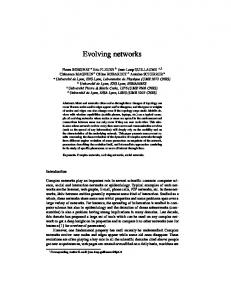
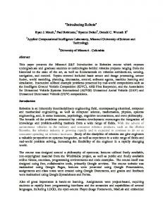
creates the illusion that each user or system owns resources of their own. Many programmable virtualization-network research projects have been carried out, and many models, including PlanetLab [20], VINI [1], GENI [2][5], and Genesis [15], have been proposed. Slices are created by network virtualization using a virtualization infrastructure (substrate) that operates the slices. In the VNode Project, network-virtualization technology was developed by Nakao et al. [17][18]. This technology makes it possible to build programmable virtual-network environments in which slices are isolated logically, securely, and in terms of performance (QoS) [9]. In these environments, new-generation network protocols can be developed on a slice without disrupting other slices. B. Structure of virtualization infrastructure In the VNode Project, it is assumed that a physical network consists of one or more domains, which are managed by a virtualization network manager (VNet manager) [13]. The VNet manager was formerly called the domain controller (DC) [18][7]. It receives a slice definition, which is a design diagram of a slice, through a Web-based portal and distributes it to VNodes in the virtualization infrastructure. The concepts of slice and slice definition in this infrastructure are defined in the following subsections. Each domain has two types of nodes: VNode and gateway (Fig. 1). An overlay technology is used in the VNode infrastructure; that is, a VNode forwards packets on the infrastructure, and each packet contains the contents of a virtual packet in a slice as the payload. VNodes are connected by tunnels using a protocol such as Generic Routing Encapsulation (GRE) [6], and the Internet Protocol (IP) is used in the current version of the virtualization infrastructure. If the IP is used in a slice, the packet format is very close to that of NVGRE [19]; however, non-IP protocols can also be used in a slice. A domain may contain conventional routers or switches that do not have virtualization functions, and VNodes can be distributed to any place connected by the IP. An arbitrary packet format and protocol can be used in a slice, so they can be used in a VNode anywhere. A VNode consists of two data-processing components, a programmer and a redirector, and a control component, a VNode manager [13]. The programmer implements virtual nodes. It enables “deep” (data-plane) programmability of virtual nodes. The redirector implements virtual links between virtual nodes by using the overlay technology. VNet manager
VNode VNM P
R VNode
User’s PC/VM
Gateway
VNode
VNet manager: Virtualization network manager VNode: Virtualization node VNM: VNode manager R: Redirector P: Programmer
VNode
IP router
VNode
Gateway
Fig. 1 Physical structure of virtualization platform
User’s PC/VM
Node Link sliver 3 Node VNode VNode sliver 1 sliver 2 Link sliver 2 User’s PC/VM
Gateway Link sliver 1
Node VNode sliver 3
Link sliver 4 IP Router Link sliver 6
VNM
Link sliver 5 Node
VNode sliver 4
Gateway User’s Link sliver 7 PC/VM
Redirector
Redirector
Original resources
Original resources
Programmer
Fig. 2 Example of slice design
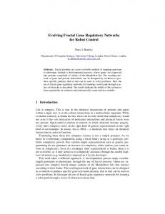
C. Structure of slices In the VNode infrastructure, a slice is a virtual network that consists of the following two components (Fig. 2) [17][18]. • Node sliver (virtual-node resource) represents computational resources that exist in a VNode (in a programmer). It is used for node control or protocol processing of arbitraryformat packets. A node sliver, which may be slow-path, i.e., a general-CPU-based virtual machine (VM), or fast-path, i.e., a specialized high-performance hardware-based virtual node that requires a special type of software. Programmability of node slivers is deep; that is, slice developers can program not only the control plane but also the data plane. • Link sliver (virtual-link resource) represents networking resources such as a virtual link that connects two node slivers and that any IP or non-IP protocols can be used on. A link sliver is mapped on a physical link between two VNodes or a VNode and a gateway. A link sliver is generated by slicing physical-network resources such as bandwidth. A slice developer can define a slice by specifying and combining these components and by programming and setting up node slivers. D. Slice definition and management A slice developer can create a slice by specifying a slice definition by using an XML-based language and sending the definition to the VNet manager (through the “northbound interface”). A slice definition is a set of specifications of the virtual network structure (such as shown in Fig. 2), nodes, and links. It may also contain virtual-to-physical node mappings. The developer can also manage the slice through the VNet manager. When creating a slice, the VNet manager maps the node/link slivers to the physical nodes/links [13] and distributes the slice definition to each VNode manager (through the “southbound interface”), which sends the necessary definitions to the data-processing components of the VNode (i.e., the programmer and the redirector): they receive information required for configuring node/link slivers. For example, a slice definition may contain a link-sliver specification such as the following (i.e., a link sliver with two virtual ports, i.e., end points: vport1 and vport2). This type of link sliver is GRE (GRE link sliver).
III. TWO-STAGE EVOLUTION METHOD FOR VNODE The method for evolving VNodes in two stages [11] is described in the following. The architecture and interfaces used
VNode in a public testbed
(a) Original stage
New VNM
VNM
Programmer
Redirector Redirector Redirector Redirector component component component Original+new resources Programmer Programmer Programmer component component component
Redirector Redirector Redirector component component component New resources Programmer Programmer component Programmer
Programmer New VNode in a public testbed
VNode extensions Extended VNode VNode
(b) Experimental stage
(c) Operational stage
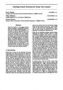
Fig. 3 Proposed VNode evolution stages
in the experimental stage are reviewed and explained more first. A. Evolution stages As for the proposed VNode-evolution method, operators (or vendors) can use plug-ins for developing new functions, such as creating, operating, or deleting new types of virtual node or link for slice developers in two stages (see Fig. 3) except the original stage. The experimental stage is mainly for the operator or vendors to develop new subcomponents of the VNode components as plug-ins, which are experimental components of the VNode infrastructure, and connect them to the components (Fig. 3(b)). Plug-ins consists of hardware and software. The operational stage is to merge the plug-ins into the components and to create an evolved VNode. An “evolvable” VNode is created for the experimental stage and, in this stage, the plug-ins can be updated at any time without affecting the operation of the original VNode. Not only the data-processing components of the original VNode but also the control and management components (i.e., the VNet manager and the VNode manager) remain unchanged. They all manage the resources and the configuration of the original virtualization infrastructure, but they do not manage the resources and configurations of plug-ins. The resources and configurations of a plug-in with dataplane functions, which is called a data plug-in, must be managed by another plug-in, which is called a control plug-in. A data plug-in may contain specialized hardware required for high performance, isolation, and QoS of slices. Because the resource managers are separated and the original managers do not recognize the new resources, such as new types of virtual node, virtual link, physical sub-node, and physical link, the original resources and the new resources must be completely separated. If the data-processing components and the control and management components of the VNode are designed to exclude interference between them and newly introduced plugins, a publicly available infrastructure can be used for developing new functions. The original VNode is probably placed in places, such as a carrier’s building, that are not easily accessible for temporary experimental purposes. However, the plug-ins can be placed in private environments for experiments, such as university laboratories or offices of vendors. The slice-development environment in the experimental stage of the VNode evolution is not friendly to slice developers. However, early adopters can define and use slices.
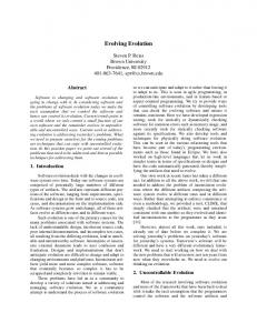
In the operational stage, an “evolved” VNode is created (Fig. 3(c)); that is, the plug-in functions developed in the experimental stage are integrated into the core part of the infrastructure. The data-plug-in functions are merged into the original data-processing component, and the functions of control plug-ins are merged into the original control and management components. Because the resource managers are merged into the core part, the original and new resources are also merged. As a result, they may be able to select the best method and resource from various methods and resources that were originally implemented in the VNode and added to it for fulfilling slice developers’ requests. Slice developers can use the new function in a similar way as other functions. B. Plug-in architecture and interfaces The plug-in architecture described here is used in the experimental stage. Plug-ins are connected to a VNode by using a predefined interface called an open VNode plug-in interface (OVPI) [11], which should be built into the dataprocessing components of the VNode (i.e., the programmer and the redirector) (see Fig. 4). The proposed plug-in architecture supports data-plane programmability and programmability of decentralized control in addition to programmability of centralized control, which is also supported by conventional software-defined networking (SDN) technologies. The data-plane (D-plane) programmability of a data plug-in and the control-plane (C-plane) programmability of a control plug-in are combined to implement a new type of virtual node or link. The data-plane and control-plane functions are separated but can be flexibly integrated; that is, the management interface between a control plug-in and a data plug-in may be a private interface, which has no predefined specification. Moreover, the plug-in architecture supports new functions created by combinations of software and hardware. Although new software is focused on in the case of future networks, new hardware will also be required. There are two types of OVPI: a D-plane interface and a Cplane interface. The D-plane interface connects data plug-ins handling data packets to slow-path or fast-path components (and to software and/or hardware components) or to a switch (which is a part of the redirector). The C-plane interface connects the control plug-ins that manage the data plug-ins and the control subcomponents of the data-processing components (i.e., programmer manager or the redirector manager). Many methods can be used to implement for an OVPI. For the C-
Controller
VNM
Redirector manager
Programmer manager Switch (Redirector part)
VNode
Slow paths & fast paths (Programmer part)
Extended VNode
OVPI for Control Plug-ins
C-plane D-plane OVPI for Data Plug-ins
Control plug-ins Redirector control plug-in Programmer control plug-in Redirector data plug-in Programmer data plug-in
Data plug-ins
Fig. 4 Open VNode plug-in (OVPI) architecture
plane interface, command-line interfaces (CLIs) and APIs (such as remote procedure calls or XMLs) can be used. For a control plug-in, the following identifiers and parameters, which are explained more in a previous paper [11], must be specified in a control message of an OVPI. The host name or address specifies the host that contains the plug-in. In usual cases, a domain name or an IP address is used, but a nonIP address or another type of name may also be used. The plugin identifier specifies a plug-in in the host. This identifier may be structured; namely, plug-ins may be hierarchical. The parameters specify control information including information that identifies the slice that the information represents. For a data plug-in, the following tag (i.e., identifier) and parameters must be specified in a data packet as an OVPI. The plug-in channel tag specifies a collection (or a channel) of plug-ins. A collection of plug-ins is specified because, in contrast to the C-plane interface, there is usually no identifier that uniquely specifies a host or a plug-in. The tag may be a protocol parameter such as a VLAN identifier. The plug-in parameters are specified as protocol parameters. The identifiers and parameters in an OVPI (for control or data plug-in) must be supplied by the slice definition in the experimental stage. Examples of slice definitions are described in the next section. IV. SLICE DEFINITION AND MANAGEMENT OF NEW TYPES OF NODES AND LINKS Slice developers can use new types of virtual nodes or links (i.e., node slivers or link slivers), which are implemented by using plug-ins. In this section, the representations of virtual nodes and links in a slice definition (which are implemented in VNodes) are described, and the method for creating and managing the nodes and links by the management and control components of the VNode infrastructure is explained. The focus of this paper is on the operational stage. However, to contrast the two stages, the method for the experimental stage, which was called “the first step” [11], is also explained here. A. Definition and management in experimental stage In the experimental stage, to use the new types of virtual nodes or links, slice developers must specify the identifiers and parameters used in an OVPI in the slice definition. Although the plug-ins and their interfaces (OVPIs) can be evolved (updated) continuously, the original control components of VNodes are kept unmodified. The identifiers and parameters must therefore be specified externally, so they are specified by the slice definition. Two examples of virtual-node and virtual-link definitions are shown in Fig. 5. The first example, shown in Fig. 5(a), is a virtual node (node sliver) implemented by a set of plug-ins. The host name or address is specified by a parameter named “ControlPort”, which specifies a CLI (for the control plug-ins). The default TCP port number is 23, but a different port may be specified as “ControlPort”. The data port, such as a MAC address, VLAN ID, or a physical port name that the data plugin is connected to, can be specified by “DataPort”. The data port is connected to the programmer (slow paths and fast paths)
…
(a) Virtual-node definition
(b) Virtual-link definition Fig. 5 A new type of virtual-node/link definitions for experimental stage
and the control port is connected to the programmer manager. Other parameters such as “Command-reserveNodeSliver” are command names of the CLI. These commands are called when the virtual node is set up, run, and stopped. See the previous paper [11] for command-parameter examples. There may be other commands such as operation and management (OAM, e.g., statistics) commands so more parameters may be specified, but they can be omitted here. The second example, shown in Fig. 5(b), is a virtual link implemented by a set of plug-ins. If the type of virtual link is built-in, the definition is the same as shown in Section II-D. Because a virtual link connects two virtual nodes in two VNodes, two sets of control and data plug-ins are specified. The control ports are CPIl1-addr and CPIl2-addr, which are connected to the redirector manager, and the data ports are DPIl1-port and DPIl2-port, which are connected to the switch (a part of the redirector). Because two control plug-ins contain the same program, the command names for the OVPI are assumed to be the same for both VNodes, namely, ls_setup_1, ls_setup_2, and so on.
Although the slice definition that uses plug-ins are complicated, such as shown in Fig. 5, it should ideally be abstract as shown in Section II-D. However, in the experimental stage, the original control and management components cannot abstract these identifiers and parameters because they do not recognize them. Moreover, these detailed specifications of identifiers and parameters, such as the domain names or addresses of the control plug-ins and physical data ports, such as MAC addresses, are convenient for developments in this stage. However, in the operational stage, these node/link definitions are too complicated for slice developers. The slice definition should therefore be simplified in the operational stage. B. Definition and management in operational stage In the operational stage, slice developers specify the new types of virtual nodes or links in slice definitions in mostly the same way as they specify built-in types. The final versions of plug-ins developed in the experimental stage are used as subcomponents of the VNode components. The hardware for the plug-ins may be moved closer to the VNode or moved inside the chassis of the VNode. Although the functions of the plugins and OVPI are not modified, the plug-ins should be authorized by the operator and should be authenticated by the network management component of the platform (i.e., the VNet manager). In this stage, to integrate the plug-ins, the original control components are modified, and the authentication information may have to be introduced to the plug-ins. With this method, however, the modification is minimum, and the tasks of the operator becomes much easier and less costly. By using the plug-in installation method proposed here, slice developers can write slice definitions for new types of virtual nodes or links, which are mostly the same as slice definitions for built-in types. The definitions, however, contain the names of the new types. The modified VNet manager and node control components (i.e., programmer manager, redirector manager, and VNode manager) contain tables to map the type names and authenticate the plug-ins and the identifiers and the parameters used in the OVPI. Therefore, it can map the names to them. The resources of the new types of nodes and links are continued to be managed by the plug-ins. However, the operator must examine the functions of the plug-ins and authorize them by registering the plug-in names and authentication information to the table. This integration process can be called the installation of the plug-ins. Two examples, which use the same plug-ins as those described in the previous subsection, are shown in Fig. 6. The first example (Fig. 6(a)) is a virtual-node definition. The second example (Fig. 6(b)) is a virtual-link definition. The syntax of these definitions are the same as those of built-in types, so they are abstract, simple, and friendly to slice developers. The only difference between predefined and newly introduced types is the subtype names, i.e., “node-type-1” and “link-type-1” in Fig. 6. These identifiers specify the sets of plug-ins indirectly. An updated control component must translate these identifiers to the identifiers and the parameters of the plug-ins. The mapping table shown in Table 1 enables this translation and also enables authentication and authorization of
… // No plug-in parameters here …
(a) Virtual-node definition // No plug-in parameters here
(b) Virtual-link definition Fig. 6 Definitions of new types of virtual-node/link for operational stage
plug-ins. Although all the information concerning this mapping is shown in a single table here, the information common to the whole platform should be managed by the VNet manager, and information on each VNode should be managed by the VNode (by the redirector manager and the programmer manager). Control plug-in identifiers and authentication information in Table 1 are used for authenticating and authorizing plug-ins. They are managed by the VNet manager, but they are sent to VNodes that contain the plug-ins for the sake of authentication. “Commands” in the control plug-in column of this table mean a list of command names for the OVPI. The list of VNodes for each virtual node or link type (i.e., VNode0, VNode1, and VNode2 in Table 1) contains all the VNodes that have the plug-in for the type. A VNode to be used for each virtual node in this slice is not necessarily specified in the slice definition. Virtual nodes are mapped by the VNet manager. The control component can thus search the table and find the plug-in identifiers and parameters. Unlike resources of built-in types of nodes and links, the resources of these new types of nodes and links are managed by control plug-ins, but not by the VNet manager. The network (resources) used by the new type of links must be independent from networks managed by the VNet manager. Therefore, the operator cannot collect resource information of all the networks from the VNet manager, and the VNet manager cannot choose resource types or optimize the whole resource usage. These are the major drawbacks of the plug-in method compared with a method with merging resource management functions Table 1 Plug-in parameter mapping table
Keys Control plug-in node-type-1 Control plug-in identifier Authorization information Commands VNode0 CPIn0-addr VNode1 CPIn1-addr VNode2 CPIn2-addr link-type-1 Control plug-in identifier Authorization information Commands VNode0 CPIl0-addr VNode1 CPIl1-addr VNode2 CPIl2-addr
Data plug-in Data plug-in identifier Authentication information DPIn0-port DPIn1-port DPIn2-port Data plug-in identifier Authentication information DPIl0-port DPIl1-port DPIl2-port
←→ Exchanging virtual link parameters
Inter-VNode C-plane Controller VNM Redirector manager
Switch (Redirector part)
VNode Extended VNode
OVPI for Control Plug-ins (CLI)
Control plug-in
Data OVPI for plug-in Data Plug-ins (VLAN) Linux PC
C-plane D-plane New type of virtual links (link slivers)
Control plug-in
Data plug-in
Inter-VNode Networks Linux PC
OVPI for Control Plug-in (CLI)
Controller VNM Redirector manager
Switch OVPI for Data Plug-ins (VLAN)
(Redirector part)
VNode Extended VNode
Fig. 7 Plug-in and interaction architecture for a new type of virtual links
proposed by the previous paper [11]. However, the advantages of this method outweigh these drawbacks. C. Control information tunneling for link management In both the experimental and operational stages, a technique called control information tunneling (CIT ), which was mentioned by the previous paper [11], is required for implementing a new type of virtual links. By using CIT, VNodes exchange virtual link parameters for control plug-ins connected to the VNodes. To create and manage a new type of link between two VNodes, the control plug-ins in the VNodes need to exchange link parameters, which cannot be controlled by the original control components of the VNodes (see Fig. 7). For example, if a GRE-based link type is predefined in the infrastructure, control components, must have a negotiation mechanism, which exchanges the end-point IP addresses and the GRE key used for the virtual link [12]. The exchanged values are sent to the control plug-ins as parameters of the OVPI (CLI) commands. However, this mechanism may be unable to exchange other types of parameters. CIT is a mechanism that allows any types of link parameters to be exchanged. The parameters should be passed through the inter-VNode control plane without interpreting or testing it. For example, if the new type of link is a VLAN-based virtual one, the control plug-ins may exchange MAC addresses and a VLAN identifier by using CIT. V. PROTOTYPING AND EVALUATION A version of the OVPIs was implemented, and a set of plug-ins was connected by using the OVPIs and partially evaluated. The hardware and software for the OVPIs and the plug-ins, the design, implementation, and preliminary results of an evaluation of the plug-ins, and the evaluation methods and results are described below. A. Hardware and software environment for plug-ins A preliminary version of the OVPIs was implemented in VNodes (in the redirectors) [11]. A CLI was used for the Cplane interface, and a VLAN-based interface was used for the D-plane interface. Data plug-ins were implemented in two sets of PCs with CentOS (Linux). Each PC had a PCIe board with a network processor, Cavium Octeon® [3]. A hardware-independent language called “Phonepl” (portable high-level open network-processing language) for network processors [10], which was called CSP, was used for developing the plug-in programs. Control plug-ins were then implemented in the PCs.
B. Implementation of a new type of virtual link A prototype of evolving and evolved VNodes (i.e., both in the experimental and operational stages), which implements a new type of virtual link, was developed. A set of OVPIs and a set of plug-ins that implements a new type of virtual link for both stages were developed, and a preprocessor for the operational stage was developed. GRE-based virtual links were the only type available in the current version of VNodes, so VLAN-based virtual links were implemented by using the plug-ins. The D-plane function of this prototype was described previously [11]. The control and management components accept slice definitions with the same format as in the experimental stage. In the present development, these components were not modified; instead, the preprocessor in this prototype translates slice definitions for the operational stage into those for the experimental stage. The preprocessor contains the whole mapping table. The preprocessor, which is written in Perl, is used before the slice definition is sent to the Web-based portal. This implementation method greatly reduces the number of tasks performed by the operator. A set of OVPIs and the plug-ins were developed as follows. The set of OVPIs is a preliminary version of the one described in Section IV. The plug-in installation method described in Section IV-C has not yet been fully developed; that is, only a link-creation function without authentication was developed. The control plug-in, which is written in C and runs on CentOS, sends a control packet to the data plug-in, which is written in Phonepl and consists of both data and control procedures. The control procedure, which adds or deletes a virtual link, works on a packet-processing core, and receives and processes a control packet [12]. The function of the control plug-in is explained below. As described in Section IV-B, to operate a virtual link correctly, control plug-ins in two VNodes, which are the end-points of the virtual link, must exchange control parameters through the inter-VNode C-plane. Because the virtual link to be created is VLAN-based, MAC addresses (and a VLAN identifier) must be exchanged. However, CIT has not yet been implemented, and VNodes currently only have the negotiation function of GRE-based virtual links. Therefore, in this preliminary implementation of a new type of virtual link, the GRE-based link parameters, i.e., IP addresses (and a GRE key), are passed to the control plug-ins and are mapped to VLAN-based link parameters, i.e., MAC addresses (and a VLAN ID). C. Evaluation A slice definition that contains two virtual nodes in two VNodes and a virtual link between them was evaluated as follows. The syntax of the node and link definitions is close to those described in Fig. 7. The preprocessor described above, which translates the simple definition to a definition that contains plug-in parameters, was used in this evaluation. The original slice definition (for the operational stage) and the translated slice definition (which can be used in the experimental stage) are compared in Table 2. The lengths (numbers of lines) of the slice definitions and the numbers of
Table 2 Result of comparing link type definitions
Definition Implementationlength (lines) dependent parameters Original (for experimental stage) 7 0 Translated (for operational stage) 14 4 Link type definition
the implementation-dependent parameters, which should be hidden from the slice developer, are listed in this table. The slice definition, which is identical to the one generated by the preprocessor, was sent to the Web-based portal, and a slice was created. Successful IP communication between the virtual nodes in this slice, connected by the VLAN virtual-link was confirmed by a ping command. Although virtual links in VNodes can transmit arbitrary format packets such as IPEC packets [8], IP was used because it requires only two OS commands (i.e., ifconfig and ping) built into the virtual node. The performance of a whole network composed of the prototype evolved VNodes was not measured, but the throughput of the data plug-in was measured to be 9 Gbps or more when the packet size was 900 bytes or larger. Although the slice developer must perform an extra step, i.e., preprocessing, the proposed VNode evolution method has a benefit for the slice developer compared with the previouslyproposed method used in the experimental stage [11]. VI. RELATED WORK OpenFlow [16] and other SDN technologies enable separation of control and data, programmability of the control plane, and centralization of network control. Network infrastructures including network nodes can be virtualized, and the control plane is evolvable by using these technologies. However, conventional SDN does not support data-plane programmability and programmability of decentralized control. These functions are also required in future networks. The plugin architecture proposed in this paper also supports these functions in combination with programmability of centralized control. JUNOS® SDK [14] of Juniper Networks supports service components as plug-ins. Each plug-in consists of control and data components. However, only one instance of a service component is created by using JUNOS SDK. This architecture is different from the plug-in architecture proposed in this paper, which supports creation of a type of virtual nodes or links by operators (or vendors) and enables creation of multiple instances of components by slice developers. VII. CONCLUSION A method for introducing new types of virtual nodes and links into a network virtualization infrastructure by evolving a physical node, which is called a “VNode”, is proposed. This evolution consists of two stages, and the operational stage was focused on in the present study. By mapping type names to plug-in identifiers and parameters, the proposed method enables abstract and simple definitions of slices by slice developers and authorization of plug-ins by the operator, but it remains the loose integration of a new function, i.e., a plug-in architecture, which is used in the experimental stage. This
extended VNode architecture supports a combination of programmable data-plane and control-plane components (i.e., plug-ins) and a combination of a decentralized (node-internal) and centralized (network-wide) control of the components. Moreover, the plug-in architecture supports new functions created by combinations of software and hardware. A prototype based on this method was developed using VNodes and evaluated. The prototyping and evaluation demonstrates that this method greatly simplifies both slice developers’ tasks and operators’ tasks; that is, both the slice specifications and the processes in the operational stage are much simplified and the changing needs of slice developers will be satisfied with reduced cost. In addition, because the proposed method may have benefits (including security benefits) for both the slice developer and the operator, it may be better to install and to authorize the plug-ins before they are initially used. Future work includes developing a method for integrated operation and management of plug-ins distributed in a virtualization platform. It also includes implementing CIT and implementing new types of virtual links and network accommodation methods, including non-IP-protocol-based ones, by using advanced technologies and methods. It also includes applying the VNode-evolution method to VNodes in JGN-X testbed. ACKNOWLEDGMENTS Part of the research results is an outcome of “Advanced Network Virtualization Infrastructure Project A” funded by the National Institute of Information and Communications Technology (NICT). The author thanks Kazuhisa Yamada from NTT, Akihiro Nakao from the University of Tokyo, Toshiaki Tarui from Hitachi, and other members of the above project for their valuable discussions on the VNode evolution and installation processes. The author also thanks Yasushi Kasugai, Kei Shiraishi, Takanori Ariyoshi, and Takeshi Ishikura from Hitachi for implementing the plug-in interfaces in the redirector. REFERENCES [1] Bavier, A., Feamster, N., Huang, M., Peterson, L., and Rexford, J., “In VINI Veritas: Realistic and Controlled Network Experimentation”, SIGCOMM 2006, pp. 3–14, September 2006. [2] Berman, M., Chase, J. S., Landweber, L., Nakao, A., Ott, M., Raychaudhuri, D., Ricci, R., and Seskar, I., “GENI: A Federated Testbed for Innovative Network Experiments”, Computer Networks, Vol. 58, No. 1, January 2014. [3] “OCTEON Programmer’s Guide, The Fundamentals”, Cavium Networks, 2010. [4] Chowdhury, N. M. M. K. and Boutaba, R., “Network Virtualization: State of the Art and Research Challenges”, IEEE Communications Magazine, Vol. 47, No. 7, pp. 20–26, July 2009. [5] Duerig, J., Ricci, R., Stoller, L., Strum, M., Wong, G., Carpenter, C., Fei, Z., Griffioen, J., Nasir, H., Reed, J., and Wu, X., “Getting Started with GENI: A User Tutorial”, ACM SIGCOMM Computer Communication Review, Vol. 42, No. 1., pp. 72–77, January 2012.
[6] Farinacci, D., Li, T., Hanks, S., Meyer, D., and Traina, P., “Generic Routing Encapsulation (GRE)”, RFC 2784, IETF, March 2000. [7] Kanada, Y., Shiraishi, K., and Nakao, A., “NetworkVirtualization Nodes that Support Mutually Independent Development and Evolution of Components”, IEEE International Conference on Communication Systems (ICCS 2012), November 2012. [8] Kanada, Y. and Nakao, A., “Development of A Scalable NonIP/Non-Ethernet Protocol With Learning-based Forwarding Method”, World Telecommunication Congress 2012 (WTC 2012), March 2012. [9] Kanada, Y., Shiraishi, K., and Nakao, A., “Network-resource Isolation for Virtualization Nodes”, IEICE Trans. Commun., Vol. E96-B, No. 1, pp. 20-30, 2013. [10] Kanada, Y., “Open, High-level, and Portable Programming Environment for Network Processors”, IEICE 7th Meeting of Network Virtualization SIG, July 2013 (in Japanese). [11] Kanada, Y., “A Node Plug-in Architecture for Evolving Network Virtualization Nodes”, 2013 Software Defined Networks for Future Networks and Services (SDN4FNS), November 2013. [12] Kanada, Y., “Controlling Network Processors by using Packetprocessing Cores”, 2nd International Workshop on Network Management and Monitoring (NetMM 2014), May 2014. [13] Katayama, Y., Yamada, K., Shimano, K., and Nakao, A., “Hierarchical Resource Management System on Network Virtualization Platform for Reduction of Virtual Network Embedding Calculation”, 15th Asia-Pacific Network Operations and Management Symposium (APNOMS 2013), September 2013. [14] Kelly, J., Araujo, W., and Banerjee, K., “Rapid Service Creation using the JUNOS SDK”, ACM Workshop on Programmable Routers for Extensible Services of Tomorrow 2009 (PRESTO’09), pp. 7–11, 2009. [15] Kounavis, M., Campbell, A., Chou, S., Modoux, F., Vicente, J., and Zhuang, H., “The Genesis Kernel: A Programming System for Spawning Network Architectures”, IEEE J. on Selected Areas in Commun., vol. 19, no. 3, pp. 511–526, 2001. [16] McKeown, N., Anderson, T., Balakrishnan, H., Parulkar, G., Peterson, L., Rexford, J., Shenker, S., and Turner, J., “OpenFlow: Enabling Innovation in Campus Networks”, ACM SIGCOMM Computer Communication Review, pp. 69–74, Vol. 38, No. 2, April 2008. [17] Nakao, A., “Virtual Node Project ― Virtualization Technology for Building New-Generation Networks”, NICT News, No. 393, pp. 1–6, Jun 2010. [18] Nakao, A., “VNode: A Deeply Programmable Network Testbed Through Network Virtualization”, 3rd IEICE Technical Committee on Network Virtualization, March 2012. [19] Sridharan, M., et al., “NVGRE: Network Virtualization using Generic Routing Encapsulation”, draft-sridharan-virtualizationnvgre, work in progress, IETF. [20] Turner, J., Crowley, P., Dehart, J., Freestone, A., Heller, B., Kuhms, F., Kumar, S., Lockwood, J., Lu, J.,Wilson, M., Wiseman, C., and Zar, D., “Supercharging PlanetLab ― High Performance, Multi-Application, Overlay Network Platform”, ACM SIGCOMM Computer Communication Review, Vol. 37, No. 4, pp. 85–96, October 2007. [21] Yamamoto, T., Katayama, Y., Yamada, K., and Nakao, A., “A Management Model for the Network Virtualization Platform to Provide Network Programmability”, World Telecommunications Congress 2012 Workshop “SDN and OpenFlow”, March 2012