to price reduction, headway limitation and avoiding inappropriate .... and 8GB of RAM as well as a notebook computer ... IEEE Transactions on Computers,.
A Method for Fast Composing of Images Captured from Deformed Documents by a Quadocular Scanner Setup Marco K¨orner Herbert S¨ uße Wolfgang Ortmann Joachim Denzler Chair for Computer Vision, Friedrich Schiller University of Jena Ernst-Abbe-Platz 2, 07743 Jena, Germany {marco.koerner, herbert.suesse, wolfgang.ortmann, joachim.denzler}@uni-jena.de
Abstract We present a fast and accurate method to compose images delivered by a quadocular document scanner into a global consistent image. The Shift Detection by Restoration (SDR) approach is used to overcome document deformations. Our method outperforms state of the art panoramic image approaches and is able to work within one second on standard hardware.
1
Introduction
The today’s increasing mobility and the raised safety consciousness demands new solutions for identifying persons like air plane passengers quickly. For this reason novel document scanner devices are requested which are capable to process this high amount of data reliably as well as fast. The FP500 (cf. Fig. 1a, [1]) is a recent developed passport scanner for applications at securityrelevant places like airports or public authorities. Due to price reduction, headway limitation and avoiding inappropriate distortions, this device is built up by four single low-cost cameras. A previous processing step provides precalibrated and undistorted images assuming an ideally planar document. Since this assumption does not hold for real documents, we describe a method to compose these partial images of naturally bended documents to a global consistent overall image. This composing step is designed using an estimation of local optical flow via Shift Detection by Restoration (SDR) [3, 8]. The main attention of this approach lies on short computation times and high accuracies even under suboptimal conditions. Furthermore, the composing result should be free of non-linear deformations to achieve the machine-readability of the document. We show that the composing step is able to provide sufficient results within less than one second on standard hardware. The remainder is structured as follows: after a short review of the related work in section 2 and a brief problem statement in section 3, our approach will be depicted in section 4. Some experimental results and a short summary and outlook will follow in sections 5 and 6, respectively.
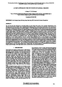
2
(a)
Related Work
The problem of image stitching or panoramic image creation is concerned in a high amount of literature. There are two main approaches: on the one hand, searching for curves in overlapping image regions to find an optimal seam by minimizing the error between these images, as presented in [5, 6, 7]. On the other hand, the approaches published in [2, 9] try to minimize
(b)
Figure 1. (a) A pathologically bended document lying on the Desko FP500 Passport Scanner [1] and (b) the result of composing according to the initial calibration.
the seam artefacts by smoothing the transitions at the stitching contour. Furthermore, Brown and Lowe published an approach for multi-row stitching in [4]. Nearly all of these panoramic image approaches premise an approximately identical optical center for all cameras recording the images to be stitched.
3
Problem Statement
In the given scenario, documents are captured by a scanner device containing four low-resolution CCD cameras. While the extrinsic calibration of these cameras assumes that the scanned document is exactly planar, this premise does not hold in real applications, e.g. due to surface deformations caused by storage and handling (cf. Fig. 1a). Even putting pressure onto the document and the glass plate bends its surface and provokes this effect. Hence the composing of the single images solely according to the calibration data fails in nearly all cases, as shown in Fig. 1b. In this section we present our approach for transforming and composing all images in order to obtain a global consistent image. The composition of the single images using any of the known panorama image algorithms induces hard local nonlinearities and deformations, which constrict further processing, e.g. optical character recognition (OCR). Common panorama image approaches premise a mutual optical center for all images to be stitched, from where the images are projected onto spherical or cylindrical surfaces. Fig. 2 shows these effects, where subfigures (a) and (b) display the result of stitching both the uncalibrated and the calibrated images with Brown’s and Lowe’s approach [4] for panorama image stitching. Note that the stitching process fails when the loop has to be closed, because the errors due to the transformations cumulate. This effect complicates further information extraction algorithms and yield undesirable results.
first patch
Figure 2. Panorama images generated by AutoStitch [4] based on (a) the uncalibrated and (b) the calibrated images.
4
Composing Approach
For composing the images, corresponding points have to be found in the image overlap areas. Based on these correspondences, transformations are estimated for all the images. To increase the accuracy, outliers are rejected and all transformations are reestimated. The final transformations are applied to the images to obtain a global consistent image. These steps will be explained in more detail in the following sections. Local optical flow estimation The transformation estimation is based on the determination of optical flow in the overlapping image regions. The Shift Detection by Restoration (SDR) approach [3, 8], which can be seen as a regularized correlation similar to the phase correlation, has been shown to give good results for point correspondence identification, especially under presence of partly periodically structured background. In contrast to the usage of spatial features, this method determines the displacement of two equal- and squaresized images in a signal-based fashion by creating a peak image, where each peak corresponds to a shift hypothesis d. In Fig. 3 some exemplary input patches are shown in context with their SDR results. As discriminating these peaks would state a strong heuristic problem, each peak hypothesis d is evaluated by the normalized cross correlation coefficient X (I0 (p) − I0 )2 · (I1 (p + d) − I1 )2 (p+d)∈I1
ρ(d) = sX (1) X (I0 (p) − I0 )2 · (I1 (p + d) − I1 )2 p∈I0
(p+d)∈I1
of the original image patch I0 and the hypothetical shifted image patch I1 , where Ik denotes the mean gray value of image Ik . The shift hypothesis with the highest value of ρ(d) is added to the set � � κ κ κ cκ = (pκ , (2) 1 , q1 ) , . . . , pnκ , qnκ κ where the tuple (pκ i , qi ) denotes a correspondence beκ tween the points pκ ∈ I0κ and qκ i i ∈ I1 in the overlapping image area κ (cf. Fig. 4).
Transformation estimation Once the optical flow fields in the overlapping regions are determined, these information are used to estimate transformations for each image. Translations and special affine transformations are used for this application. As depicted
(c)
(d)
(e)
(f)
(g)
(h)
(i)
second patch
(b)
(b)
SDR result
(a)
(a)
Figure 3. Image patches with (a, d) structured background, (b, e) foreground shifted horizontally and (c, f) vertically and (g–i) their SDR images, where white peaks are indicating the shift hypotheses. Note the suitability of this method for the partial periodical background structure of the images.
in Fig. 4, each transformation is assembled by opposing shear mappings and translations. Using these parameters, the transformation matrices M0 M1 M2 M3 z }| { }| { }| { }| { z z z � � � � � � � � 1 s0x 1 −s0x 1 −s3x 1 s3x M= (3) , , , 0 1 1 0 sy 1 sy 1 −sy 1 −sy 1 and translation vectors 1 1 2 2 3 3 0 0 t = (ax , ay ) = 0, (ax , ay ), (ax , ay ), (ax , ay ) {z } | {z } | {z } | {z } | t0
t1
t2
(4)
t3
can be built. To enforce global consistency, the transformation matrices are circularly linked by mutual parameters. With respect to these transformations, each b is originated from input pixel p according target pixel p to b = M−1 p i · (p − ti ),
i ∈ {0, . . . , 3} , p ∈ Ii .
(5)
The free parameters are estimated by solving the linear equation system stated in App. A in the least-squares sense. The first translation vector t0 = (a0x , a0y ) is fixed in order to obtain a unique result, while the weighting factor ωκ = (nt +nr +nb +nl )/nκ stated in App. A ensures that no overlapping area is favored over the others. Outlier rejection As a consequence of the presence of homogeneous areas and the poor camera resolution, the displacement vector fields are likely to contain some outliers disrupting the transformation estimation. For this reason, an outlier rejection is used to achieve an outlier-free displacement vector field. Given the complete shift vector field, initial transformations are estimated. According to these transformations, the correspondences with the highest backprojection errors are removed. These steps are repeated recursively until some predefined abort criterion, e.g. the highest tolerable error, is satisfied.
3.5
Run Time in Seconds
3
Full Interpolation, Notebook Input Image Interpolation, Notebook No Interpolation, Notebook Full Interpolation, Desktop Input Image Interpolation, Desktop No Interpolation, Desktop
2.5 2 1.5 1 0.5 0 16
32
48
64 80 Patch Sizes in Pixels
96
112
128
Figure 6. Runtimes obtained for composing the document shown in Fig. 7a on different hardware environments. Figure 4. The transformations to be estimated and their parameters.
(a)
(b)
Figure 5. An optical flow vector field within the upper overlapping area (a) before and (b) after outlier rejection.
Fig. 5 shows an exemplary displacement vector field of the upper overlapping region before and after the outlier rejection.
5
Examples and Experimental Evaluation
Since this approach optimizes the visual quality of the composed image, just some exemplary results are shown in Fig. 7 in place of quantitative measures. Practical experiences show that OCR performed on the resulting images is working correctly in about 95% the cases. For evaluating the runtimes of this method, we performed tests on a desktop computer equipped with an R Intel CoreTM 2 Quad Q9300 CPU at 2.50 GHz and 8 GB of RAM as well as a notebook computer R with an Intel SU4100 CPU at 1.3 GHz and 2 GB of RAM. For our time measurements we used the bended document shown in Fig. 7a and tried to compose it both with interpolation during the initial precalibration as well as the full document composing and without any interpolation. We implemented our methods in C++ disregarding any further optimization techniques like parallelization or specialized data structures. In Fig. 6 one can see, as expected, that the runtime of our approach is strongly correlated with the size of the patches used for the shift detection. The abrupt declinations were caused by the SDR-intern Fourier transforms benefiting from patch sizes of the powers of two. Obviously, the interpolations were responsible just for a small amount of the runtimes, which can be dropped without a noticeable loss of quality. On desktop computers, documents with displacements up to 55 pixels can be composed within one second. For
displacements of about 40 pixels, composing times of about half a second are possible. Reproducing the experiments on the notebook setup solely doubled the runtime.
6
Conclusion and Outlook
We presented an approach to compose subimages taken of a bended document using a quadocular camera setup. Our method used a signal-based correspondence detection via SDR. Experiments showed that our proposal yields accurate results as well as moderate computation time. For further speedup, the parallelism of the independent image processing steps should be exploited. Furthermore the Fourier transforms used by SDR could also be implemented on parallel hardware architectures like GPUs in order to decrease the runtime.
References [1] Desko FP 500 Passport Scannner/Verifier. Data sheet, Desko GmbH, Bayreuth, Germany, 2007. [2] E. H. Adelson, J. R. Bergen, P. J. Burt, and J. M. Ogden. Pyramid methods in image processing. RCA Engineer, 29(6):33–41, 1984. [3] T. Baumbach and W. Ortmann. Shift detection by restoration demonstrated by signal based point pattern matching. In ICIAP, pages 310–315, Washington, DC, USA, 1999. IEEE Computer Society. [4] M. Brown and D. G. Lowe. Automatic panoramic image stitching using invariant features. International Journal of Computer Vision, 74(1):59–73, 2007. [5] J. Davis. Mosaics of scenes with moving objects. In CVPR, pages 354–360, Washington, DC, USA, 1998. IEEE Computer Society. [6] A. A. Efros and W. T. Freeman. Image quilting for texture synthesis and transfer. In SIGGRAPH, pages 341–346, New York, NY, USA, 2001. ACM. [7] D. L. Milgram. Computer methods for creating photomosaics. IEEE Transactions on Computers, 24(11):1113–1119, 1975. [8] H. S¨ uße, K. Voss, W. Ortmann, and T. Baumbach. Shift detection by restoration. In CAIP, pages 33–40, London, UK, 1999. Springer-Verlag. [9] M. Uyttendaele, A. Eden, and R. Szeliski. Eliminating ghosting and exposure artifacts in image mosaics. CVPR, 2:509, 2001.
A
Equation System used for Parameter Estimation 0
0
0
0
0
t −(pt1,y +q1,y )·ωt
0
0
0
0 ωt
0
0
0
0
0
−pt1,x ·ωt
t ·ωt q1,x
0
.. .
.. .
ωt . . . ωt 0 ωr 0 .. . ωr 0 0 0 . . . 0 0 0 0 . . . 0 0
.. .
.. .
.. .
.. .
.. .
0
0
0
0
0
ωt
0
0
0
0
0
0
0
0
−ωr
0
0
0 −ωr ωr
0
.. .
.. .
.. .
.. .
.. .
0
0
0
.. .
−(
t ptn ,y +qn t t ,y
0
0
−pr 1,y ·ωr
−ptn ,x ·ωt t 0
t qn ·ω t ,x t 0
0
0
r (pr 1,x +q1,x )·ωr
.. .
.. .
.. .
0
0
0
ωr
0
−ωr
0
0
−pr nr ,y ·ωr 0
0
ωb
0
−ωb
0
0
0
r (pr nr ,x +qnr ,x )·ωr 0
0
0
ωb
0
−ωb
0
pb 1,x ·ωb
b q1,x ·ωb
.. .
.. .
.. .
.. .
.. .
.. .
.. .
.. .
0
ωb
0
−ωb
0
0
0
0
0
0
ωb
0
−ωb
0
pb nb ,x ·ωb
b qn ·ω b ,x b
0
0
0
ωl
0
l ·ωl −q1,y
0
0
0
0
0
0
ωl
0
l +pl1,x )·ωl −(q1,x
0
.. .
.. .
.. .
.. .
.. .
.. .
.. .
.. .
0
0
0
ωl
0
l −qn ·ωl l ,y
0
0
0
0
ωl
0
0 −ωr
|
B
)·ωt
0 � � l +pln ,x ·ωl − qn ,x l l
{z
A∈R10×2·(nt +nr +nb +nl )
0 0
t )·ωt (pt1,x −q1,x (pt −q t )·ω t 1,y 1,y t (pt nt ,x −qnt ,x )·ωt t (pt nt ,y −qnt ,y )·ωt (q r −pr )·ωr 1,x 1,x (q r −pr )·ωr 1,y 1,y r (q r nr ,x −pnr ,x )·ωr (q r −pr nr ,y )·ωr n ,y r (q b −pb )·ωb 1,x 1,x b −pb (q1,y 1y )·ωb b (q b nb ,x −pnb ,x )·ωb b (q b nb ,y −pnb ,y )·ωb l l (q1,x −p 1,x )·ωl (q l −pl 1,y 1,y )·ωl l (q l nl ,x −pnl ,x )·ωl l l (qn −p nl ,y )·ωl l ,y
.. . 0 0 r q1,y ·ωr 1 0 ax .. a2x a2 . y r ·ωr qn a3 j ,y x3 0 ay b +q ·ω −(pb ) b · a3 1,y 1,y y 0 0 sx0 .. sy . s1 � � y b b − pn ,y +qn ,y ·ωb b b s3 x 0 | {z10} x∈R pl1,y ·ωl 0 .. . l pn ,y ·ωl l
0
.. .
.. .
=
.. .
.. .
|
}
{z
}
b∈R2·(nt +nr +nb +nl )
Exemplary Results
(a)
(b)
(c)
(d)
Figure 7. These images show (a) an extremely bended document and (c) a checkerboard image both composed according to the initial calibration and the results of our approach in Figures (b) and (d) respectively. Note the extent of the affine transformations visualized by the straight lines highlighted in image (b) as well as the checkerboard structure in image (d).