create a reference architecture for agent-based systems. This paper presents a ... For each agent framework implementation under analysis, implement a basic ap- plication that ..... Cougaar mobility follows a ticketing system pattern (Fig. 4(b)).
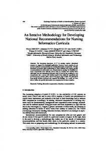
A Methodology for Developing an Agent Systems Reference Architecture Duc N. Nguyen1 , Kyle Usbeck1 , William M. Mongan1 , Christopher T. Cannon1 , Robert N. Lass1 , Jeff Salvage1 , William C. Regli1 , Israel Mayk2 and Todd Urness2 1
2
Applied Communications and Information Networking Institute, Drexel University {dn53, kfu22, wmm24, ctc82, urlass, jks29, regli}@drexel.edu Communications-Electronics Research, Development and Engineering Center, US Army
Abstract. The slow adoption of agent-oriented methodologies as a paradigm for developing industry systems is due in part to their lack of integration and generalpurpose use. There exists a need to define common patterns, relationships between components, and structural qualities that a reference architecture for agentbased systems would solve. However, there is little, if any, consensus on how to create a reference architecture for agent-based systems. This paper presents a methodology for developing a reference architecture that documents agent-based systems from different system viewpoints. Rather than the traditional approach of studying existing systems, the documentation methodology relies on forensic software analysis of agent frameworks (i.e., APIs and libraries for constructing agent systems). We demonstrate the methodology by describing the process used to create the Agent System Reference Architecture.
1
Introduction
Using agent-based approaches for constructing large complex distributed systems can provide advantages over traditional methods [5]. Unfortunately, industry has been slow to adopt this agent-oriented paradigm. One reason for this slow adoption is the lack of integration and general-purpose technologies [13]. Standards bodies such as the Foundation for Intelligent Physical Agents (FIPA)3 are leading efforts to standardize protocols and formats of an agent-based system. However, there is a need to construct a reference architecture that defines the relationships between standardized terms and concepts of an agent-based system. Furthermore, such an architecture would give a set of architectural blueprints and best practices to aid in developing new agent frameworks and systems. To this end, a reference architecture for agent-based systems would speed other standardization efforts and adoption as a viable systems engineering perspective. This paper describes a documentation methodology for creating the Agent Systems Reference Architecture (ASRA) for agent frameworks. Rather than studying agent systems across unrelated application domains, this work studies the agent frameworks used to construct software systems composed of agents. The ASRA builds upon the Agent Systems Reference Model (ASRM) [11] by identifying and documenting the interactions between ASRM functional concepts typically found in an agent system. 3
http://www.fipa.org
Our approach to creating the ASRA for agent frameworks combines static and dynamic software analysis tools with a regimented documenting process 4+1 View Model [6] to existing agent framework implementations creating five architectural views. The process for creating the ASRA is as follows: 1. For every ASRM functional concept, the ASRM definiton of each functional concept comprises the Scenario view of the 4+1 Model. 2. For each agent framework implementation under analysis, implement a basic application that exercises the functional concept. Execute this application within an application profiler to generate runtime data to build the Process view. 3. Perform static analysis on the source code of the agent system functional concept to build the Implementation view. 4. Finally, abstract the package decompositions into the Logical view. The main contribution of this paper is a novel methodology for creating reference architectures for a class of systems based on a domain reference model. Previous approaches rely on studying classes of existing systems and constructing reference architecture documents. Moreover, we believe this methodology is general enough to apply to other software system domains. The rest of this paper is organized as follows: Section 2 defines the terms architecture, reference architecture in the context of agent systems and agent frameworks. Section 2.2 describes the Agent Systems Reference Model and its basis for creating the ASRA. Section 3 provides a description of the 4+1 Model and how it will be applied to agent frameworks followed by an application of the process to create a portion of the ASRA in Section 4. Section 5 provides a summary of related efforts in reference architectures for agent-based systems. Finally, we conclude with related efforts and a roadmap of this continuing work for developing a reference architecture for agent systems.
2
Background
This section defines a reference model and a reference architecture. We use these definitions to further define a reference architecture for agent systems. 2.1
What is a Reference Model and Architecture?
A reference model describes the abstract functional elements of a system. A reference model does not impose specific design decisions. APIs, protocols, encodings, and other standards are not included within a reference model, but can be use concurrently. A reference model does not explicitly define an architecture, but rather can drive the implementation of multiple architectures. The novelty of a reference model is that it provides a common ontology, innovative and practical system engineering techniques, and software development guidance [11]. A software architecture is an abstract representation of a software system. It is composed of structures and components of the system, their properties, and the relationships between them [2]. A reference architecture has many definitions, but the most
commonly used in the software engineering literature is that a reference architecture consists of standardized diagrams (e.g., UML, ADL, etc.) that describe the architecture from different viewpoints to cover the concerns of the stakeholders of a system. These standardized diagrams are used to abstract the implementation details of a system and illustrate the relationships between the components of a system [14]. 2.2
A Reference Model for Agent Systems
Infrastructure
The basis for the ASRA is the Agent Systems Reference Model (ASRM) [11]. The ASRM provides a model for software systems composed of agents. It establishes terms, concepts, and definitions required to compare agent systems. The ASRM defines an intelligent agent—or simply agent—as situated computational processes that embody Agent one or more of the following qualiAgent System ties: autonomy, proactivity, interactivAgent ity, continuous, sociality, and/or mobilReasoner ity. The ASRM also formalizes conSensor Effector cepts and layers of organization in an Interface Interface agent-based system. The layers (shown n-to-1 in Figure 1) are: agents, frameworks, Agent Framework(s) n-to-1 platforms, hosts, and environments. An Platform(s) agent-based system is the set of framen-to-1 works, the agents that execute in them, Host(s) the platform (other software) that supn-to-1 ports them and the hosts (hardware) upon Environment which they execute. The ASRM describes an agent sysFig. 1. Anatomy of an agent and its role in an tem as a set of abstract functional conagent system. cepts that support overall system execution. The functional concepts represent the complex interactions between software and hardware located at different layers of the agent system. The functional concepts are as follows: – Agent Administration facilitates and enables command and control of agents and allocates resources to those agents as needed. – Security and Survivability prevents execution of undesirable actions within an agent system while allowing execution of desirable actions. – Mobility facilitates and enables the migration of agents among framework instances (typically, but not necessarily, on different hosts) – Conflict Management facilitates and enables the management of interdependencies between agents activities and decisions. – Messaging facilitates and enables information and data transfer among agents in the system.
– Logging facilitates and enables information about events to be recorded occurring during system execution for subsequent inspection. – Directory Services facilitates and enables the locating and accessing of shared resources. The functional concepts are necessary in developing the ASRA as they are the starting point for the analysis process. 2.3
The Agent Systems Reference Architecture
The Agent Systems Reference Architecture (ASRA) is an elaboration of the ASRM. It establishes relationships between the ASRM functional concepts in agent frameworks and defines patterns for these concepts. The ASRA does not address implementation specifics but rather describes possible interactions between functional concepts. A reference architecture for agent systems can be defined from the standpoint of the individual agent functionality, the agent framework, the group and agent societies, or the system-to-system interaction viewpoints. In this work, we focus on the agent frameworks because the functional concepts defined in the ASRM are largely implemented in these frameworks.
3
Serial Approach to Constructing the ASRA
We construct the ASRA by applying reverse engineering methods on sample applications built using existing open source agent frameworks. We systematically build multiple view models by analyzing popular agent framework implementations: JADE4 , Cougaar5 and AGLOBE6 . These agent frameworks were chosen for analysis because of their popularity in the agent system community and the availability of their source code and documentation. Agent systems have a broad definition and have many applicable domains, studying a particular fielded system or class of systems may not cover all the architectural variations of a reference architecture. Therefore, we study agent frameworks rather than fielded systems or specific domains. This approach avoids the endless debate of the exact definition of an agent and intelligence and simply addresses the systems composed of agents. Adapting the Rational/4+1 View Model: The Rational/4+1 View Model [6, 7] creates different architectural descriptions, or views, of software systems for different interested parties (e.g. system developers, business-persons, customers). Each view identifies and describes the relationships between components and concepts. Interested parties will view these relationships with different weights and significance. The views in the 4+1 Model are as follows: 4 5 6
http://jade.tilab.com http://www.cougaar.org http://agents.felk.cvut.cz/aglobe
– The Logical View describes the static structural layout of the software system from the perspective of a software developer. – The Process View describes the runtime behavior of the system, including concurrency relationships and ordered tasks carried out by components of the system from the perspective of a workflow designer or manager. – The Implementation View describes the package layout of the system from the perspective of the system architect. – Deployment View describes the hardware-software configurations at a platformlevel as viewed by system administrators or deployment teams. – Scenario View is the “+1” view that spans the other four views. This crosscutting view is composed of narrative use cases to provide an executive level view of the architecture. The ASRA is documented using the Scenario, Process, Logical, and Implementation Views. Each ASRM functional concept is documented with these four views to cover the needs of agent system architects, developers, agent framework designers, and system users. The ASRA does not present the Deployment view because this view addresses the needs for system administrators and deployment teams. The Serial Approach: The goal of the serial approach is to produce overlapping series of documents and diagrams detailing many views of a system from different perspectives. We document the most abstract views first and augment each with software analysis data and domain knowledge to create the next view. We mine for software architecture data by performing static and dynamic analysis of multi-agent frameworks [10]. For each functional concept defined in the ASRM apply the following process: 1. Construct the Scenario View for a functional concept. The scenario view consists of functional concept definitions from the ASRM including possible interactions with other functional concepts. The scenario view for each functional concept consists of UML use-case diagrams and/or descriptions depicting the use, role, and functionality of the concept. 2. Construct the Process View from the Scenario View. We implement a snippet of code exercising the functional concept for each agent framework. Execute this snippet of code and use the dynamic runtime analysis framework, Enterprise Java Profiler (EJP)7 , to generate trace data. With this trace data, construct a UML process diagram to illustrate a concrete architecture for the functional concept for a particular agent framework. After constructing process diagrams for each agent framework, create a new process diagram from the common features across the agent framework implementations while documenting differences as points of variation. This abstract architecture for the functional concept and the points for variation comprise the Process View. 3. Construct the Implementation View using the static analysis tools, BAT [4] to identify data flow and package/class dependencies of each functional concept. We use 7
http://ejp.sourceforge.net
these software tools on the agent frameworks and code snippets from Step 2. Focusing on the code snippets allows us to bypass extraneous information such as dead code and common library dependencies. We construct a UML component diagram for each agent framework. Components represent the modules and packages and connectors represent interdependencies. Next we construct an abstract architectural package representation by identifying similar packages and modules from the concrete architectures. Different packages are documented as points of variabilion. 4. Construct the Logical View using the Bunch clustering system [9] and the static analysis data from the previous step. The Logical View consists of UML package diagrams of a functional concept. This abstract architectural representation of a functional concept is created from the concrete architectural views of the agent frameworks. The clustered data, represented as a graph, illustrates interdependencies between components (edges) and modules (nodes) within the agent framework implementation. Highly connected modules indicate components and subsystems within an agent framework implementation. UML package diagrams depict the the concrete logical architecture of each agent framework implementation where packages are the modules and the connectors are interdependencies. Packages within other packages represent interdependencies that do not travel outside the enclosing package. From the concrete logical architectures of the agent framworks, we create an abstraction noting similarities and differences. The differences are documented as points of variation. The result yields the agent systems reference architecture consisting of four documents for each ASRM functional concept.
4
Application of the Serial Approach
To demonstrate the serial approach, we step through the documentation process for the mobility functional concept by analyzing agent framework implementations: Jade, AGLOBE, and Cougaar. 4.1
The Scenario View for Agent Mobility
The Scenario View of the ASRA, based on the 4+1 View Model, contains scenarios and use cases of a system’s architecturally significant behavior. Mobility Definition: Mobility is the process by which an agent migrates from one executing platform instance to another. The functional concept use cases (ellipses) are depicted in a UML use-case diagram (Fig. 2). The move agent (moving an agent from one container to another) and the clone agent (making a copy of an agent in another container) use cases are invoked by the container (represented by an actor). Note, this figure also illustrates interactions between the Agent Administration and Directory Services functional concepts. For example, the clone agent use case uses the create agent, modify agent state use case.
Key
Use Case Actor Functional Concept
«use»
One Use Case "using" another Use Case
Fig. 2. The Mobility functional concept use case diagram and the interactions with the Agent Administration and Directory Services functional concept.
4.2
The Process View for Agent Mobility
The Process view documents the runtime behavior of a functional concept based on a code snippets for each agent framework. Executing EJP on code snippets yield runtime traces. The runtime trace illustrates the percentage of time spent in methods during execution. The runtime trace (Fig. 3(a)) shows a temporal view of the mobility functional concept and illustrates the invocation points of the agent mobility functional concept. From the runtime trace, we create a UML activity diagram (Fig. 3(b)). Mobility Process View Patterns: We repeat this process for AGLOBE and Cougaar to construct similar Process diagrams. Comparing the diagrams, two patterns for agent mobility emerge. Jade and AGLOBE exhibit Serialization mobility (Fig. 3(c)) in which an agent’s execution is paused, converted into a transferable form, transmitted to a target platform, converted into an executable form, and resuming agent’s execution. Cougaar exhibits shared-object mobility in which agents are shared between platform containers and the agent’s state is synchronized across platforms during execution. Agent mobility is achieved by changing the shared state to the new platform location. 4.3
The Implementation View for Agent Mobility
The Implementation view is the static view of the agent system derived through static code analysis tools and temporal data from the process view. UML component diagrams depict the high-level components of a functional concept and their interactions with other components and functional concepts. Mobility Implementation View Patterns: The two patterns for Mobility from the Implementation view (Fig. 4): serialization mobility and ticketing mobility.
(a) Runtime Trace for Jade Mobility.
(b) Activity Diagram for Jade Mobility.
Key start
Activity
The progression of activities
(c) Mobility Process View: Serialization Pattern. Fig. 3. Jade Mobility runtime trace and resulting concrete architecture Process view diagram. Comparing architecture diagrams for each agent framework leads to an abstract architecture for the mobility functional concept.
Jade and AGLOBE mobility follow a serialization mobility pattern (Fig. 4(a)). The Platform Discovery component uses Directory Services to find the destination platform. The Agent Encapsulation component creates a representation of the mobile agent for transport. The Messaging component delivers the mobile agent to the destination platform. Finally, the Agent Extraction component receives the mobile agent, loads it in the platform, and resumes its execution. Cougaar mobility follows a ticketing system pattern (Fig. 4(b)). The Platform Discovery component uses the Directory Services component to find the destination platform. A Mobility Factory component generates a ticket ID to identify the destination platform of the mobile agent. Finally, the Mobile Agent component uses messaging functional concept to publish the ticket to the other hosts. 4.4
The Logical View for Agent Mobility
The Logical Views express the high level packages and interacting components existing in an agent system. The Logical View is constructed by observing the clustered runtime data generated from EJP and BAT and organizing the major objects into packages. This organization is represented with UML package diagrams. Mobility Logical View Patterns: The Logical view for Mobility depicts two patterns: Serialization Mobility and Shared Object Mobility. Jade and AGLOBE follow the serialization pattern in which the agent is converted to a transferable form before migrating the agent to its destination. The Mobility functionality (Fig. 5(a)) depends on the agent administration to pause and start the agent and messaging components to transmit the agent. Cougaar follows the shared object mobility pattern in which the agent representation is shared among platforms. Agent mobility involves synchronizing the state of the agent then halting the agent on the source platform and initializing and executing the agent on the target instance. Shared object mobility (Fig. 5(b)) depends on the agent administration component for halting and initializing the agents, the messaging component for synchronizing the state, and directory services for finding the target platform.
5
Related Work
In developing the methodology for creating the ASRA, we studied two related areas of research: approaches and methodologies for creating a reference architecture, and reference architecture related to agent-based systems. The multiple view presentation for the ASRA is adopted from the ISO/IEEE1471 [1] recommendation for architecture documentation. Another example of presenting a reference architecture in multiple views is the Reference Architecture Foundation for Service Oriented Architectures (RAF-SOA) [8] from the OASIS foundation. The RAFSOA presents a reference architecture for SOA systems. Moreover, similar to the ASRA, the RAF-SOA is based on the definitions, layered OASIS reference model for service oriented architectures.
Key
Directional Interaction
(a) UML Component diagram for serialization mobility
(b) UML Component diagram for ticketing mobility
Fig. 4. Implementation View: Two Patterns for Mobility.
(a) Serialization paradigm: The migration component depends on the agent execution manager and serialization components of the agent controller component and the messaging component.
(b) Shared Object paradigm: The migration component depends on the directory services component, the agent controller component, and the messaging component.
Fig. 5. The Logical View: two paradigms for Mobility.
The process for creating a reference architecture for systems in a regimented manner is often addressed through analyzing existing and deployed systems. The Product Line Software Engineering, Domain-Specific Software Architecture (PuLSE-DSSA) [3] is a process for creating reference architectures in an iterative fashion. PuLSE-DSSA still depends on instantiated architectures. Architecture Structure Description Language (ASDL) also depends on existing systems to find commonalities to abstract a reference architecture. This process is does not directly aid in constructing new agent frameworks. Reference architectures for agent-based systems has been studied to a limited extent. The FIPA Abstract Architecture Specification8 discusses agent system architecture in an effort to promote interoperability and reusability. FIPA provides a generic view on agent systems and describes how specific functionality should interact. FIPA provides lowlevel details such as mechanisms for how agents perform service look-ups. The ASRA also focuses on identifying architectural paradigms and patterns in agent frameworks but focuses on the higher level, implementation-agnostic interactions. Weyns and Holvoet [12] developed a Reference Architecture for Situated Multiagent Systems. This reference architecture focuses on the agent operating in an application environment. This architecture was developed through an interative process of analysis and validation studying different agent-based systems. In their reference architecture, the authors constructed multiple documents from different views: the module decomposition, the shared data, and the communicating processes views. This reference architecture approach focuses on the agent in the environment whereas the ASRA address the infrastructure of the environment.
6
Conclusion and Future Work
The Agent Systems Reference Architecture (ASRA) is an ongoing effort to create a reference architecture for agent-based systems. The primary contribution of this work is the serial process for creating a reference architecture for an agent systems. This process begins with functional concepts defined by the ASRM and serially applies dynamic and static software analysis of agent framework implementations. The resulting architecture is a set of architectural views depicting relationships and structural qualities among instantiated functional components. In future work, we will apply this process on the rest of the ASRM functional concepts to present a full architecture for agent frameworks. Moreover, we intend to extend this process to include a Deployment view of agent systems. The Deployment view presents the architecture of an agent system as it would be situated in the physical environment. Addressing how conceptual components of an agent system is beneficial to agent system architects, developers, and system integrators in identifying real-world issues in system engineering. Furthermore, we intend to address the paradigms of how agent systems interoperate with external systems (e.g. agents integrated with web services). 8
http://www.fipa.org/specs/fipa00001
References 1. ANSI/IEEE. Recommended practice for architectural description of software-intensive systems, 2009. http://www.iso-architecture.org/ieee-1471. 2. L. Bass, P. Clements, and R. Kazman. Software Architecture in Practice. Addison-Wesley Professional, 2003. 3. Jean-Marc DeBaud, Oliver Flege, and Peter Knauber. PuLSE-DSSA – a method for the development of software reference architectures. In ISAW ’98: Proceedings of the third international workshop on Software architecture, pages 25–28, New York, NY, USA, 1998. ACM Press. 4. M. Eichberg. BAT2XML: XML-based java bytecode representation. Electronic Notes in Theoretical Computer Science, 141(1):93–107, December 2005. Proceedings of the First Workshop on Bytecode Semantics, Verification, Analysis and Transformation (Bytecode 2005). 5. N. R. Jennings. An agent-based approach for building complex software systems. Commun. ACM, 44(4):35–41, 2001. 6. P. Kruchten. Architectural blueprints—The “4+1” view model of software architecture. IEEE Software, 12(6):42–50, November 1995. 7. P. Kruchten. The rational unified process: an introduction. Addison-Wesley Longman Publishing Co., Inc. Boston, MA, USA, 3rd edition, 2003. 8. Ken Laskey, Jeff A. Estefan, Francis G. McCabe, and Danny Thornton. Reference architecture foundation for service oriented architecture. Technical report, OASIS, 2009. http://docs.oasis-open.org/soa-rm/soa-ra/v1.0/soa-ra.html. 9. S. Mancoridis, B.S.Mitchell, Y.Chen, and E.R.Gansner. Bunch: A clustering tool for the recovery and maintenance of software system structures. August 1999. 10. W. M. Mongan, C. J. Dugan, R. N. Lass, A. K. Hight, J. Salvage, W. C. Regli, and P. J. Modi. Dynamic analysis of agent frameworks in support of a multiagent systems reference model. IADIS International Conference Intelligent Systems and Agents, 2007. 11. W. C. Regli, I. Mayk, C. J. Dugan, J. B. Kopena, R. N. Lass, P. J. Modi, W. M. Mongan, J. K. Salvage, and E. A. Sultanik. Development and specification of a reference model for agentbased systems. IEEE Trans. On Systems, Man, and Cybernetics, Part C, 39(5):572–596, Sep. 2009. 12. D. Weyns and T. Holvoet. A reference architecture for situated multiagent systems. Lecture Notes in Computer Science, 4389:1, 2007. 13. D. Weyns, H. V. D. Parunak, and O. Shehory. The future of software engineering and multiagent systems. Special issue on Future of Software Engineering and Multi-Agent Systems, International Journal of Agent-Oriented Software Engineering (IJAOSE), 2008. 14. Yonghua Zhou, Yuliu Chen, and Huapu Lu. UML-based systems integration modeling technique for the design and development of intelligent transportation management system. In Proceedings of the 2004 IEEE International Conference on Systems, Man and Cybernetics, The Hague, The Netherlands, 2004. IEEE, IEEE.