the key scheduling algorithm by means of a key round. Our ..... reg. slices. (cycles). (Mhz). (Mhz). Pipeline RIJNDAEL. 33712 14592 17984. 0. 42. 1. 172.
A Methodology to Implement Block Ciphers in Reconfigurable Hardware and its Application to Fast and Compact AES RIJNDAEL François-Xavier Standaert, Gael Rouvroy, Jean-Jacques Quisquater, Jean-Didier Legat
g
{standaert,rouvroy,quisquater,legat @dice.ucl.ac.be
UCL Crypto Group Laboratoire de Microélectronique Université Catholique de Louvain Place du Levant, 3, B-1348 Louvain-La-Neuve, Belgium ABSTRACT
1.
Reprogrammable devices such as Field Programmable Gate Arrays (FPGA’s) are highly attractive options for hardware implementations of encryption algorithms and this report investigates a methodology to efficiently implement block ciphers in CLB-based FPGA’s. Our methodology is applied to the new Advanced Encryption Standard RIJNDAEL and the resulting designs offer better performances than previously published in literature. We propose designs that unroll the 10 AES rounds and pipeline them in order to optimize the frequency and throughput results. In addition, we implemented solutions that allow to change the plaintext and the key on a cycle-by-cycle basis with no dead cycles. Another strong focus is placed on low area circuits and we propose sequential designs with very low area requirements. Finally we demonstrate that RAM-based implementations implies different constraints but our methodology still holds.
In September 1997, the NIST 1 issued a request for possible candidates for a new Advanced Encryption Standard (AES) to replace the Data Encryption Standard (DES). In August 1998, 15 candidates algorithms were selected and a year later, in August 1999, five finalists were announced: MARS, RC6, SERPENT, RIJNDAEL and TWOFISH. On 2 October 2000, the RIJNDAEL algorithm, developed by Joan Daemen and Vincent Rijmen was selected as the winner of the AES development race. In performance comparison studies carried out on all five finalists, RIJNDAEL proved to be one of the fastest and most efficient algorithms. It is also implemented on a wide range of platforms and is extendable to different key and block lengths.
Categories and Subject Descriptors B.7.1 [Algorithms implemented in Hardware]; E.3 [Data encryption]
General Terms Algorithms, Security, Design, Performance
Keywords AES RIJNDAEL, Reconfigurable hardware, FPGA, Cryptography, High encryption rates
Permission to make digital or hard copies of all or part of this work for personal or classroom use is granted without fee provided that copies are not made or distributed for profit or commercial advantage and that copies bear this notice and the full citation on the first page. To copy otherwise, to republish, to post on servers or to redistribute to lists, requires prior specific permission and/or a fee. FPGA’03, February 23–25, 2003, Monterey, California, USA. Copyright 2003 ACM 1-58113-651-X/03/0002 ...$5.00.
INTRODUCTION
As opposed to custom hardware or software implementations, little work exists in the area of block cipher implementations within existing FPGA’s. Results available in the public literature sometimes mention encryption rates comparable with software ones. We believe that these performances can be greatly improved using today’s technology as soon as inherent constraints of FPGA’s are taken into account. In this paper, we propose a methodology to efficiently implement block ciphers within commercially available FPGA’s, based on similarities between configurable logic blocks available in FPGA’s and encryption algorithms. It actually consists in simple digital design rules adapted to FPGA constraints. It is applied to RIJNDAEL and allows to improve previously reported results in terms of hardware cost, throughput or efficiency. We also suggest that different constraints have to be considered if some parts of the algorithm are implemented into the RAM blocks available in present FPGA’s. Improved RAM-based implementations of RIJNDAEL are proposed in order to confirm this assumption. This paper is organized as follows. The description of the hardware, synthesis tools and implementation tools is in sec1
NIST : National Institute of Standards and Technology.
* This work has been funded by the Walloon region (Belgium) through the research project TACTILS.
tion 2. Section 3 gives a short mathematical description of RIJNDAEL and we propose an efficient representation of the key scheduling algorithm by means of a key round. Our design methodology is proposed in section 4 and applied to RIJNDAEL in section 5. Comparisons between our implementation results and other published designs are in section 6 and conclusions are in section 7.
LUT’s and 64896 flip-flops. In the next sections, we compare the number of LUT’s, registers and slices. We also evaluate the delays and frequencies thanks to our synthesis tool. The synthesis was performed with FPGA Express 3.6.1 (SYNOPSYS) and the implementation with XILINX ISE-4. Finally, our circuit models were described using VHDL.
3. 2.
HARDWARE DESCRIPTION
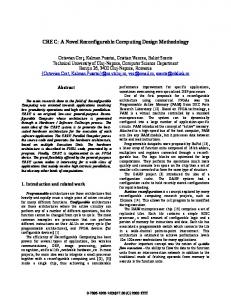
All our implementations were carried out on XILINX VIRTEX1000BG560-6 and XILINX VIRTEX3200ECG1156-8 FPGA’s. We chose these technologies in order to allow relevant comparisons with the best-known FPGA implementations of RIJNDAEL. In this section, we briefly describe the structure of a VIRTEX FPGA as well as the synthesis and implementation tools that were used to obtain our results. Configurable Logic Blocks (CLB’s): The basic building block of the VIRTEX logic block is the logic cell (LC). A LC includes a 4-input function generator, carry logic and a storage element. The output from the function generator in each LC drives both the CLB output and the D input of the flip-flop. Each VIRTEX CLB contains four LC’s, organized in two similar slices. Figure 1, shows a detailed view of a single slice. Virtex function generators are implemented as 4-input look-up tables (LUT’s). In addition to operate as a function generator, each LUT can provide a 16×1-bit synchronous RAM. Furthermore, the two LUT’s within a slice can be combined to create a 16×2-bit or 32×1-bit synchronous RAM or a 16×1-bit dual port synchronous RAM. The VIRTEX LUT can also provide a 16-bit shift register. The storage elements in the VIRTEX slice can be configured either as edge-triggered D-type flip-flops or as level-sensitive latches. The D inputs can be driven either by the function generators within the slice or directly from slice inputs, bypassing function generators. The F5 multiplexer in each slice combines the function generator outputs. This combination provides either a function generator that can implement any 5-input function, a 4:1 multiplexer, or selected functions of up to nine bits. Similarly, the F6 multiplexer combines the outputs of all four function generators in the CLB by selecting one of the F5multiplexer outputs. This permits the implementation of any 6-input function, an 8:1 multiplexer, or selected functions up to 19 bits. The arithmetic logic also includes a XOR gate that allows a 1-bit full adder to be implemented within an LC. In addition, a dedicated AND gate improves the efficiency of multiplier implementations. Finally, VIRTEX FPGA’s incorporate several large RAM blocks. These complement the distributed LUT implementations of RAM’s. Every block is a fully synchronous dualported 4096-bit RAM with independent control signals for each port. The data widths of the two ports can be configured independently. Our hardware: A VIRTEX1000BG560-6 FPGA contains 12288 slices and 32 RAM blocks, which means 24576 LUT’s and 24576 flip-flops. A VIRTEX3200ECG1156-8 FPGA contains 32448 slices and 208 RAM blocks, which means 64896
BLOCK CIPHER DESCRIPTION
RIJNDAEL is an iterated block cipher that operates on a 128-bit cipher state and uses a 128-bit key2 . It consists of a serie of 10 applications of a key-dependent round transformation to the cipher state. In the following, we will individually define the component mappings and constants that build up RIJNDAEL, then specify the complete cipher in terms of these components. Representation: The state and key are represented as a square array of 16 bytes. This array has 4 rows and 4 columns. It can also be seen as a vector in GF (28 )16 . Let s be a cipher state or a key ∈ GF (28 )16 , then si is the i-th byte of the state s and si (j) is the j-th bit of this byte. Bytesub, the non-linear layer γ: The Bytesub transformation is a non-linear byte substitution, operating on each byte independently. The substitution table (or s-box) is invertible and is constructed by the composition of two operations: 1. The multiplicative inverse in GF (28 ). 2. An affine transform over GF (2). Every byte is therefore considered as a polynomial with coefficients in GF (2): b(x) = b7 x7 +b6 x6 +b5 x5 +b4 x4 +b3 x3 + b2 x2 + b1 x1 + b0 x0 . b7 b6 b5 b4 b3 b2 b1 b0 → b(x)
(1)
Then bytesub consists of the parallel application of this sbox S: γ(a) = b ⇔ bi = S[ai ], 0 ≤ i ≤ 15
(2)
The Shiftrow transformation δ: In Shiftrow, the rows of the state are cyclically shifted over different offsets. Row 0 is not shifted, row 1 is shifted over 1 byte, row 2 over 2 bytes and row 3 over 3 bytes. The Mixcolumn transformation θ: In Mixcolumn, the columns of the state are considered as polynomials over GF (28 ) and multiplied modulo x4 + 1 with a fixed polynomial c(x), given by: c(x) =0 030 x3 +0 010 x2 +0 010 x +0 020
(3)
4
The polynomial is coprime to x + 1 and therefore is invertible. This can be written as a matrix multiplication: 2 3 2 3 2 3 b0 02 03 01 01 a0 6 b1 7 6 01 02 03 01 7 6 a1 7 6 7 6 7 6 7 4 b2 5 = 4 01 01 02 03 5 × 4 a2 5 b3 03 01 01 02 a3 2 Actually, there exist several versions of RIJNDAEL with different block and key lengths, but we focus on this one.
Figure 1: The VIRTEX slice.
Where (b3 , b2 , b1 , b0 ) is a four-byte column of the state. An output byte of mixcolumn (for example b0 ) can be expressed as3 : b0 =0 020 × a0 +0 030 × a1 +0 010 × a2 +0 010 × a3
The round transformation ρ[K]: The round transformation can be written as a composition of the four precedent transformations4 : ρ[K] = σ[K] ◦ θ ◦ δ ◦ γ
(6)
(4) We also define a function X, corresponding to the multiplication with ’02’ modulo the irreductible polynomial m(x) = x8 + x4 + x3 + x + 1: X : GF (28 ) → GF (28 ) : X(a) = b ⇔ b(7)
=
a(6)
b(6)
=
a(5)
b(5)
=
a(4)
b(4)
=
a(3) ⊕ a(7)
b(3) b(2)
= =
a(2) ⊕ a(7) a(1) ⊕ a(7)
b(1)
=
a(0)
b(0)
=
0 ⊕ a(7)
The key schedule can be easily described by the use of a key round β that takes four 4-byte input words, corresponding to a 128-bit key, and produces four 4-byte output words. The first round key K0 is the cipher key, then, we have:
The round key addition σ[K]: In this operation, a round key is applied to the state by a simple bitwise EXOR. The round key is derived from the cipher key by means of the key schedule. The round key length is equal to the block length. σ[k](a) = b ⇔ bi = ai ⊕ ki , 0 ≤ i ≤ 15
3
⊕ is the bitwise EXOR operation.
The key schedule: The round keys are derived from the cipher key by means of the key schedule. This consists of two transformations: the key expansion and the round key selection. In our description, Subsyte (SB) is a function that takes a 4-byte word in which each byte is the result of applying the RIJNDAEL s-box. The function Rotbyte (RB) returns a word in which the bytes are a cyclic permutation of those in its inputs such that the input word (a, b, c, d) produces the output word (b, c, d, a). Finally, RC(i) is a 8-bit round constant for the round i.
(5)
Ki+1 = β(Ki ), i = 0, ..., 10
(7)
Figure 2 illustrates the key round of Rijndael where registers needed for efficiency purposes are already mentioned. The complete cipher: Rijndael is defined for the cipher key K as the transformation Rijndael[K]= α[K0 , K1 , ..., K10 ] applied to the plaintext where: α[K0 , K1 , ..., K10 ] = σ[K10 ]◦δ ◦γ ◦(°9r=1 ρ[Kr ])◦σ[K0 ] (8) � 4 Read σ[K] θ(δ(γ)) .
RC (i )
K i ,0
R B
S B
⊕
⊕
K i ,1
⊕
⊕
K i,2
K i +1, 2
⊕
K i ,3
K i +1,0 K i +1,1
K i +1,3
Figure 2: The key round β.
ters if needed because they allow more efficient implementations than repeated registers.
Our implementations are based on this description of AES Rijndael.
4.
5. Build the complete cipher from these optimal components and implement the resulting design.
DESIGN METHODOLOGY:
FPGA’s are very efficient devices and they are suitable for high work frequencies. However the CLB structure described in section 2 involves constraints to take into account if an optimal design is wanted. As the slice of Figure 1 is divided into logic elements and storage elements, an efficient implementation will be the result of a better compromise between logic used, storage used and resulting performances. Typically, the designer tries to limit its critical path inside one CLB slice without consuming slices for register usage only. Most modern block ciphers are iterated5 and their round function usually consists of very simple algebraic or logic operations. As a consequence, they are suitable for efficient FPGA implementations by nature and the following methodology is a relevant tool to obtain good circuits. It actually consists in simple digital design rules applied to FPGA’s. 1. Implement every basic component of the block cipher. Synthetise them and compute their LUT cost and critical path. 2. Insert registers in the basic components in order to limit the critical path inside one slice. The number of registers needed should never exceed the number of LUT’s computed in step 1. An efficient usage of the slice implies to take advantage of additional EXOR gates and multiplexors available in the slice. 3. Combine basic components if they offer possible optimizations. Registers do not need to be placed between components only. 4. Build the round and the key round and adapt their number of pipeline stages if different. Use shift regis5 The block cipher is defined as the application of a number of key-dependant transformations called round function.
At every step, efficiency can be checked by computing the ratio N br of LU T 0 s/N br of registers. It always should be close to one. Let the efficiency of a block cipher be the ratio Area (slices)/T hroughput (M bits/s). This methodology allows to get very efficient designs after synthesis. However, the implementation (specially the place and route step) of large designs is often difficult and sometimes implies additional constraints that can be overcome by modifying some parts of the design. This explain the frequently large difference between estimated frequency after synthesis and work frequency after implementation. In the next section, we illustrate this methodology and apply it to the block cipher RIJNDAEL.
5.
IMPLEMENTATION:
In order to allow relevant comparisons with existing FPGA implementations of RIJNDAEL, we performed different experiments with different technologies, depending on the use of RAM blocks to implement the substitution box or on the FPGA used: VIRTEX or VIRTEX-E. In the next section, the delay is estimated after synthesis6 , with a VIRTEX1000BG560-6.
5.1
Components:
Bytesub, the non-linear layer γ: We implemented Bytesub as a large multiplexor, and took advantage of FPGA configurations to implement these ones. The upper part of Figure 6 illustrates the implementation of the Rijndael sbox. We pipelined γ by inserting two registers so that the critical path corresponds to one 4-input LUT, one multiplexor F5 and one multiplexor F6. Table 1 summarizes the synthesis results for the non-linear transform γ where the 6
FPGA Express (SYNOPSYS).
Component γ
Nbr of LUT 144 × 16 = 2304
Nbr of registers 42 × 16 = 672
Estimated delay (ns) 5.8
Table 1: Synthesis of the non-linear layer γ.
a7
a6
a5
a4
a3 ⊕
⊕ b7
b6
b5
b4
a2
b3
a1 a0
a7
a6
a5
a4
b1
b7
b6
b5
⊕
⊕
⊕
Ki ⊕
⊕
⊕
b0
b4
a2
⊕
⊕
⊕ b2
a3
b3
a1 a 0
a3
a2 a 0
⊕
⊕ ⊕
⊕ b2
b1
b0
⊕
⊕
⊕
⊕
Figure 3: The function X. ⊕
s-box is repeated 16 times. Another possibility is to use the RAM blocks available inside the VIRTEX to implement substitution boxes. The resulting bytesub transform uses 8 RAM blocks and is performed in one clock cycle. We discuss the RAM-based implementations of RIJNDAEL in section 6. The shiftrow transformation δ: This is just routing information and takes no place in the design. The Mixcolumn transformation θ: Mixcolum operates on a 4-byte column and corresponds to multiplications and additions in GF (28 ). For example, for the output byte b0 , we have: b0 =0 020 a0 +0 030 a1 +0 010 a2 +0 010 a3
(9)
We implemented multiplications with a function X that corresponds with the multiplication with ’02’, modulo the irreducible polynomial m(x) = x8 + x4 + x3 + x + 1. Figure 3 illustrates the function X. Note that output bits 0,2,5,6,7 just correspond to input bits shifted. Only 3 bits are modified by an EXOR operation. From this, we can easily represent an output byte of θ as shown in Figure 4: b0 = X(a0 ) ⊕ X(a1 ) ⊕ a1 ⊕ a2 ⊕ a3
(10)
Interesting combinations between Mixcolumn and the key addition can be performed when observing the structure of the Virtex slice (see Figure 1). Indeed, we observe that a slice offers the possibility to perform an EXOR between 5 bits: four bits are managed by the LUT and the last one by an EXOR gate next to the LUT. We will take advantage of this and try to keep our critical path inside one Virtex slice. Combining Mixcolumn and Addroundkey: The Mixadd transform ². On Figure 4, we observe that an output byte of θ is obtained by a bitwise EXOR between 5 bytes: 3 are input bytes and the remaining ones are output bytes of X. However, looking at the bit level, we know that 5 output bits of X are just shifted input bits. For these ones, only one register is needed to pipeline the diffusion layer. For the 3 remaining bits, there is an additional EXOR inside
c7
c6
c5
c4
⊕
c3
⊕
c2
c1 c0
Figure 5: The Mixadd transform ² at the bit level.
the function X. Therefore, for these bits, we compute the bitwise EXOR between the 3 left bytes of Figure 4 and the output bits of X independently. Then we insert a register. A bitwise EXOR operation remains to be carried out and we combine it with the key addition. The resulting Mixadd transformation only needs two register levels to keep a critical path inside one slice. Figure 5 illustrates the combination of Mixcolumn and Addroundkey at the bit level. Finally, Table 2 summarizes the synthesis results for the Mixadd transformation.
5.2
The round and key round functions:
Based on the above components, we can build the round and key round functions and evaluate their hardware cost. Figure 6 illustrates the round function of Rijndael. Figure 2 illustrates its key round. Both contain 4 registers levels. Note that Subbyte has the same inner structure as Bytesub and therefore the same number of register levels. The synthesis results for the round ρ and key round β functions are given in table 3.
6. 6.1
COMPARISONS: LUT-based implementations:
In [3, 4, 5, 6, 7], different LUT-based FPGA implementations of RIJNDAEL encryption are proposed within a VIRTEX1000. In the next section, we propose designs implemented on the same technology and compare them with existing results.
a0
a1
a3
a2
a0
a1
a2
a3
X
X
X
X
⊕ b0 Figure 4: Output byte b0 of the Mixcolumn transform θ.
Component ²
Nbr of LUT 304
Nbr of registers 304
Estimated delay (ns) 4.8
Table 2: Synthesis of the Mixadd transform ².
Component LUT-based round LUT-based key round
Nbr of LUT 2608 768
Nbr of registers 976 488
Estimated delay (ns) 5.8 5.8
Table 3: Synthesis of the round and key round.
Type Pipeline RIJNDAEL Sequential RIJNDAEL
Nbr of LUT 33712 3916
Nbr of reg. 14592 2132
Nbr of slices 17984 2257
RAM blocks
Latency (cycles)
0 0
42 52
Output every (cycles) 1 5/52
Freq. after Synt. (Mhz) 172 172
Table 4: RIJNDAEL encryption implementations on VIRTEX1000.
Type Gaj et al. Dandalis et al. Elbirt et al. Our design
Nbr of slices 2900 5673 9004 2257
Device VIRTEX1000 VIRTEX1000 VIRTEX1000 VIRTEX1000
Throughput (Mbits/s) 331.5 353 1940 1563
Throughput/Area bits/s ( Mslices ) 0.11 0.06 0.22 0.69
Table 5: Comparisons with other LUT-based implementations.
Freq. after Impl. (Mhz) / 127
128
LUT F5
γ
txt
key
F6
σ
⊕
key(1)
β
state(1) key(2)
ρ
LUT
β
state(2)
F5
ρ
key(3)
...
state(3)
...
β
state(9)
δ
ρ
key(9)
β
state(10)
γ
ε
δ
128
σ
key(10)
⊕ cipher
Figure 6: The round function ρ.
Figure 7: Pipeline AES Rijndael.
Our implementations of AES Rijndael directly results from the component descriptions. We decided to implement a pipeline version that unrolls the 10 RIJNDAEL rounds (illustrated on Figure 7) and a sequential version with only one unrolled round (illustrated on Figure 8 where the grey functions are actually included in the round ρ). We observed the hardware cost in terms of LUT’s, registers and slices as well as the frequency results. In this section, the frequency is estimated after synthesis7 and implementation8 . On Table 4, we observe very high frequencies after synthesis. However, critical delays mainly occur when trying to place and route these synthesis results. The resulting implemented designs have surprising critical paths including 20% of logic and 80% of routes. We conclude that the real bottleneck of such large ciphers is the difficulty of having an efficient place and route. Actually, constraints come from shift registers and high fanout. Implementation could probably be improved by inserting registers but this additional degree of freedom for the routes would be balanced with additional ressources . We conclude that in case of critical routing delays, designs having logic paths over two (or more) slices can be considered. However, if our design methodology is applied, no slice should be used for register usage only and therefore this should not change the area requirements. Anyway, the resulting designs are very efficient as shown in Table 5 where we list the most efficient implementations within VIRTEX1000 FPGA’s. Note that our pipeline design would be even more efficient but cannot fit into a VIRTEX1000. 7 8
FPGA Express (SYNOPSYS). Xilinx ISE4.
txt
σ
⊕
key
key(1)
state(1)
ρ
β key(r)
γ δ
σ
⊕
key(10)
cipher
Figure 8: Sequential AES Rijndael.
txt
6.2
key
RAM-based implementations: key(1)
In [9, 10, 11], RAM-based FPGA implementations of RIJNDAEL encryption are proposed within a VIRTEX-E FPGA. In the next section, we propose designs implemented on the same technology and compare them with existing results.
σ
4. A 21-cycle sequential version with a 2-cycle round: the register after the multiplexor is removed. Table 6 summarizes the implementation results of our different RAM-based RIJNDAEL encryption modules. It clearly illustrates that the high pipelining used in CLB-based implementations do not lead to optimal circuits. Actually, the most efficient solutions correspond to situations where logic paths cover two slices. The key difference with CLBdominated designs is the lower area requirements of the design that causes slices to be used for register usage only if high pipelining is performed. However, our methodology still holds: step 2 mentioned that the number of registers of components should never exceed the number of LUT’s needed. Optimal designs have well balanced logic and register requirements. Our 21-cycle solutions have this interesting property: their ratio N br of LU T 0 s/N br of registers is close to one. Note that in case of sequential circuits, as high pipelining is no more wanted, it is also possible to modify the round structure so that initial and final key additions can be managed by the round function. This leads to very low area circuits as pictured on Figure 9. The resulting designs improves the previously reported RAM-based implementations as shown in Table 7.
β
δ cipher
θ LAST ROUND
1. A 42-cycle pipeline or 52-cycle sequential version with a 4-cycle round: a register is added after the RAMbased substitution box.
3. A 21-cycle pipeline or 31-cycle sequential version with a 2-cycle round: the register inside the mixadd transform ² is also removed.
key(r)
γ
As we previously mentioned, it is possible to implement the substitution boxes of RIJNDAEL in the RAM blocks available in present VIRTEX-E. Although this could result in very efficient implementations, it also involves different design constraints. When RAM blocks are used, a strong bottleneck arises when trying to place and route large designs. This make the optimal pipelining of CLB’s completely ineffective. In order to illustrate this assumption, we decided to implement different RAM-based solutions, where only the number of pipeline stages differs:
2. A 32-cycle pipeline or 42-cycle sequential version with a 3-cycle round: the register after the RAM-based substitution box is removed.
⊕
Figure 9: Modified sequential AES Rijndael.
7.
CONCLUSIONS
We propose a methodology to implement block ciphers in reconfigurable hardware and applied it to RIJNDAEL. Inherent constraints of FPGA’s are taken into account in order to get very efficient circuits. We investigated different possible implementations: CLB-dominated or RAM-based, pipeline or sequential. These implementations involve different constraints but the design methodology holds as long as we keep the ratio N br of LU T 0 s/N br of registers close to one. Efficiency is measured as the ratio Area (slices)/T hroughput (M bits/s) and we obtain very efficient designs. A strong focus is placed on high throughput and low area and we implemented solutions for both criteria. Upon comparison, our designs offer better results than previously reported in literature. Compact and high speed architectures are proposed and implemented on VIRTEX and VIRTEX-E technologies. Throughput is up to 14 Gbits/s and area requirements can be limited to 405 slices and 10 RAM blocks. Bottlenecks arises in the routing of our synthesis results. This could certainly be improved and this last point could deserve further analysis.
8.
REFERENCES [1] Xilinx: Virtex 2.5V Field Programmable Gate Arrays Data Sheet, http://www.xilinx.com. [2] J.Daemen and V.Rijmen, The Block Cipher RIJNDAEL, NIST’s AES home page, http : //www.nist.gov/aes. [3] A.J.Elbirt et Al, An FPGA Implementation and Performance Evaluation of the AES Block Cipher Candidate Algorithm Finalists, The Third Advanced Encryption Standard (AES3) Candidate Conference, April 13-14 2000, New York, USA. [4] K.Gaj and P.Chodowiec, Comparison of the Hardware Performance of the AES Candidates using Reconfigurable Hardware, The Third Advanced Encryption Standard (AES3)
Type Pipeline RIJNDAEL Pipeline RIJNDAEL Pipeline RIJNDAEL Sequential RIJNDAEL Sequential RIJNDAEL Sequential RIJNDAEL Sequential RIJNDAEL Modified sequential
Nbr of LUT 4912 4272 3516 1036 965 877 877 709
Nbr of reg. 7792 6832 3840 1452 1372 932 668 413
Nbr of slices 5144 4032 2784 866 739 550 542 405
RAM blocks
Latency (cycles)
100 100 100 10 10 10 10 10
42 32 21 52 42 31 21 20
Output every (cycles) 1 1 1 5/52 4/42 3/31 2/21 2/20
Freq. after Synt. (Mhz) 285 232 208 285 232 208 208 192
Freq. after Impl. (Mhz) 112 92 92 147 135 117 119 87
Table 6: RIJNDAEL encryption implementations on VIRTEX3200E. Type McLoone et al. Our design Helion tech. Our design
Nbr of LUT’s / 3516 899 877
Nbr of slices 2222 2784 / 542
RAM blocks 100 100 10 10
Device VIRTEX810E VIRTEX3200E VIRTEX3200E VIRTEX3200E
Throughput (Mbits/s) 6956 11776 1187 1450
Throughput/Area M bits/s ( slices,LU ) T 0s 3.1 4.2 1.32 1.65
Table 7: Comparisons with other RAM-based implementations.
[5]
[6]
[7]
[8]
[9]
[10]
[11] [12]
Candidate Conference, April 13-14 2000, New York, USA. P.Chodowiec et al, Experimental Testing of the Gigabit IPSec-Compliant Implementations of RIJNDAEL and Triple-DES Using SLAAC-1V FPGA Accelerator Board, in the proceedings of ISC 2001: Information Security Workshop, LNCS 2200, pp.220-234, Springer-Verlag. A.Dandalis et al, A Comparative Study of Performance of AES Candidates Using FPGA’s, The Third Advanced Encryption Standard (AES3) Candidate Conference, April 13-14 2000, New York, USA. T.Ichikawa et al, Hardware Evaluation of the AES Finalists, The Third Advanced Encryption Standard (AES3) Candidate Conference, April 13-14 2000, New York, USA. O.Kwon et al, Implementation of AES and Triple-DES Cryptography using a PCI-based FPGA Board, in the proceedings of ITC-CSCC 2002: The International Technical Conference On Circuits/Systems, Computers and Communications. M.McLoone and J.V.McCanny, High Performance Single Ship FPGA RIJNDAEL Algorithm Implementations, in the proceedings of CHES 2001: The Third International CHES Workshop, Lecture Notes In Computer Science, LNCS2162, pp 65-76, Springer-Verlag. M.McLoone and J.V.McCanny, Single-Chip FPGA Implementation of the Advanced Encryption Standard Algorithm, in the proceedings of FPL 2002: The Field Programmable Logic Conference, Lecture Notes in Computer Science, LNCS 2147, p.152ff. Helion Technology, High Performance AES (Rijndael) Cores for XILINX FPGA, http : //www.heliontech.com. V.Fischer and M.Drutarovsky, Two Methods of RIJNDAEL Implementation in Reconfigurable
Hardware, in the proceedings of CHES 2001: The Third International CHES Workshop, Lecture Notes In Computer Science, LNCS2162, pp 65-76, Springer-Verlag. [13] A.Rudra et al, Efficient RIJNDAEL Encryption Implementation with Composite Field Arithmetic, in the proceedings of CHES 2001: The Third International CHES Workshop, Lecture Notes In Computer Science, LNCS2162, pp 65-76, Springer-Verlag. [14] A.Satoh et al, A Compact RIJNDAEL Hardware Architecture with S-Box Optimization, Advances in Cryptology - ASIACRYPT 2001, LNCS 2248, pp239-254, Springer-Verlag. [15] CAST, AES Encryption Cores, http : //www.cast − inc.com.