A MODELLING STUDY TO COMPARE TRIPOLAR AND MONOPOLAR CUFF ELECTRODES FOR SELECTIVE ACTIVATION OF NERVE FIBRES 1
2
1
1
S.Parrini , V.Legat , J.Delbeke , C.Veraart 1
Neural Rehabilitation Engineering Laboratory, Universite Catholique de Louvain; 54 Ave. Hippocrate; box UCL 54.46; B 1200 Brussels, Belgium; (send e-mail to:
[email protected]). 2
Applied Mechanics Department, Universite Catholique de Louvain; 4 Ave. Lemaitre, B 1348 Louvain-la-Neuve, Belgium.
Abstract - We developed a mathematical model to compare selectivity simulated performances of tripolar and monopolar cuff electrodes. An original technique which combines Finite Element Method and Fourier's series development is used to find the electric field distribution at low computational cost. Results show that, as far as rectangular pulses are considered, tripolar and monopolar cuff electrodes qualitatively offer similar selectivity possibilities. For activation of inner fibres, monopoles require lower currents than tripoles. Anodal block allows selective activation of inner fibres.
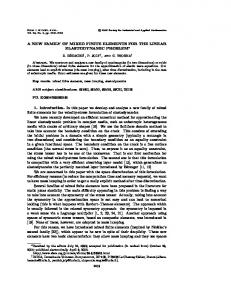
I. INTRODUCTION Functional Electrical Stimulation as a method for restoring neural activity is nowadays an important area of research. In particular, stimulation by implanted spiral cuff nerve electrodes can allow selective activation of regions inside the nerve trunk [1]. Mathematical modelling is a useful tool to study design of such cuff in order to optimise selectivity. In this work, we develop a model and we use it in order to compare selectivity performances of tripolar and monoplar cuff electrodes. An anisotropic and non-homogenous nerve model is adopted, and a cuff electrode with three longitudinally aligned dot contacts is considered. When simulating a tripole, current is assumed to be injected by the external contacts (anodes) and to be absorbed by the central one (cathode); when simulating a monopole, current injected by a distant anode, flows through the boundary of the domain and is absorbed by the central contact (the other two are not used). For each of the two configurations, rectangular pulses of variable duration and amplitude are considered and maps of the activated regions within the nerve are computed and drawn. These activation maps provide an original qualitative tool to compare selectivity performances of the two configurations. II. METHOD Fig.1 shows the geometry of the volume conductor domain. The nerve is composed of a cylindrical fascicle surrounded by perinerium and epinerium; connective tissue and saline are present between the nerve and the cuff; the electrode is composed of a cylindrical insulating cuff and three longitudinally aligned metal contacts, recessed in cuff thickness. The nerve and cuff are considered immersed in saline.
r θ
m s2
i s1 c e p f
z
Fig.1: Transversal and longitudinal sections of the Volume Conductor. Only a quarter of the whole sections is reported because of symmetries. The drawing is not at scale. Subdomain labeled by (f) represents the cylindrical nerve fascicle (radius 2500 µm, transversal conductivity 0.1 S/m, longitudinal 1 S/m). It is surrounded by the following layers (label - name - thickness[µm] conductivity[S/m]): (p) perinerium, 35, 0.00336; (e) epinerium, 50, 0.008; (c) connective tissue, 400, 0.0659; (s1) saline, 30, 2; (s2) saline, 5000, 2; (i) insulating cuff, 400, 10-6; (m) metal contacts, 25, 104. The total length is 42 mm; the cuff is 11.2 mm long, the contacts have 1mm2 square surface and are recessed in the cuff thickness by 75 µm; the distance between the cathode and the anodes is 5 mm (centre to centre).
Under quasi-static assumptions, electric field distribution inside the volume conductor, due to current injection by the electrode, is described by Laplace's equation [2]. This equation has been solved in [3] and [4] by a 3D Finite Element Method (FEM): results show that variation of the solution with respect to coordinate θ (see fig.1) is quite smooth. In fact, the problem is mainly axisymmetric, except for contacts; for this geometry we developed a suitable technique. We suggest to approximate the solution by a linear combination of given functions:
u(r, z,θ ) ≈
N
M
j =0 k =1
U
j k
φk (r, z) cos( jθ )
where u is the unknown electric potential field and the j
(1)
φk
are
2D FEM shape functions. The Uk are unknown coefficients which are determined by Galerkin's technique. Note that we only need a two-dimensional FEM mesh, since φ k functions are defined in (r, z) plane.
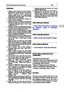
T RI P OL E
PW = 0 .1 ms ; I = 0 .5 mA
PW = 0 .1 m s ; I = 1 .1 7 5 mA
PW = 0 .5 ms; I= 1 .1 mA
M ON OP OL E
PW = 0 .1 m s ; I = 0 .5 mA
PW = 0 .1 m s ; I = 0 .8 4 5 mA
PW = 0 .5 ms; I = 0 .9 mA
Fig.2: Activation maps illustrating nerve regions which are activated by rectangular pulses (dark coloured areas); PW=pulse width; I=intensity.
Once the potential field is known in the whole domain, we draw out its values at the nodes of Ranvier of a selected fibre at a given position inside the fascicle, and then study its behaviour using the Sweeney's fibre excitation model [5]. In order to draw the activation maps, we mesh the transversal section of the fascicle by 36 radial sectors, with 17 nodes on each radius: at each node location, a fibre is considered and action potential propagation is analysed. Accordingly, 612 fibres make up the activation map picture. This technique is implemented in the frame of the NumLab software project developed in the Applied Mechanics Department of UCL. III. RESULTS Activation maps for both configurations are shown in fig.2. In the left column, activation of superficial fibres is shown: pulse width is set to 0.1 ms and current is fine-tuned in order to reach the threshold of a given test fibre (the same in both activation maps). In the central column, inner fibres are activated, the test fibre being choosen deeper in the fascicle. Right column shows activation of inner fibres together with blocking of superficial ones (anodal block): pulse width is set to 0.5 ms and current tuned in order to reach blocking threshold of the same test fibre as in the left column. IV. DISCUSSION Results show that, as far as rectangular pulses are considered, tripolar and monopolar electrodes qualitatively offer similar recruitment performances. For activation of inner fibres, monopoles require lower currents than tripoles.
Nevertheless, these results need generalisation. Accordingly, equivalence should be consistently assessed in different conditions (pulse shapes, boundary conditions, nerve geometries and so on). We showed that anodal block offers an additional selectivity tool, allowing activation of inner fibers without superficial ones. This leads us to believe that a wide range of selective activation strategies can be dealt with when working with multi-contacts electrodes, i.e. when more than one contacts array is present in the insulating cuff. Acknowledgement Partially supported by grant BMH4-CT-96-0897. REFERENCES [1] Veraart C., Grill W.M., Mortimer J.T., «Selective control of muscle activation with a multipolar nerve cuff electrode», IEEE Trans. Biomed. Eng., 40: 640-653, 1993 [2] Plonsey R., «Bioelectric phenomena», McGraw-Hill, 1969. [3] Chintalacharuvu R.R., Ksienski D.A., Mortimer J.T., «A numerical analysis of the electrical field generated by a nerve cuff electrode », Proc. 13th Ann.Conf. IEEE-EMBS; 13(2): 912-913,1991;. [4] Delbeke J., «The electric field induced by an external electrode within the nerve trunk»(in French), Master Thesis, Université Catholique de Louvain (Belgium); 1993. [5] Sweeney J.D. , Mortimer J.T., Durand D., «Modelling of mammalian myelinated nerve for functional neuromuscular stimulation», Proc. 9th Ann.Conf. IEEE-EMBS: 1577-1578, 1987.