application domain, from a common set of core assets us- ing analogous means of ..... the artefacts across the software development lifecycle. That is, it provides ...
The Journal on Software and Systems Modeling manuscript No. (will be inserted by the editor)
A Model-Driven Traceability Framework for Software Product Lines Nicolas Anquetil1 , Uir´ a Kulesza2 , Ralf Mitschke3 , Ana Moreira2 , Jean-Claude Royer1 , Andreas 4 Rummler , Andr´ e Sousa2 ? 1 2 3 4
ASCOLA, EMN-INRIA, Nantes, France CITI/DI/FCT, Universidade Nova de Lisboa, Portugal TU Darmstadt, Germany SAP Research, Dresden, Germany
Received: date / Revised version: date
Abstract Software product line (SPL) engineering is a recent approach to software development where a set of software products are derived for a well defined target application domain, from a common set of core assets using analogous means of production(for instance, through Model Driven Engineering). Therefore, such family of products are built from reuse, instead of developed individually from scratch. Software product lines promise to lower the costs of development, increase the quality of software, give clients more flexibility and reduce time to market. These benefits come with a set of new problems and turn some older problems possibly more complex. One of these problems is traceability management. In the European AMPLE project we are creating a common traceability framework across the various activities of the SPL development. We identified four orthogonal traceability dimensions in SPL development, one of which is an extension of what is often considered as “traceability of variability”. This constitutes one of the two contributions of this paper. The second contribution is the specification of a metamodel for a repository of traceability links in the context of SPL and the implementation of a respective traceability framework. This framework enables fundamental traceability management operations, such as trace import and export, modification, query and visualization. The power of our framework is highlighted with an example scenario.
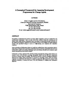
of software products by reusing a common set of features, or core assets, that are shared by these products. In SPL engineering (SPLE) a substantial effort is made to reuse the core assets, by systematically planning and controlling their development and maintenance. Thus, a peculiarity of SPLE is the variability management [7, 38, 40], that is, the ability to identify the variation points of the family of products and to track each product variant. In contrast to single system software engineering, SPLE yields a family of similar systems, all tailored to fit the wishes of a particular market niche from a constrained set of possible requirements. The software product lines development process consists of two main activities (see Figure 1): Domain engineering and Applications engineering. These activities are performed in parallel, each with a complete development cycle, consisting of, for example, requirements engineering, architecture design and implementation. The complexity of SPLE poses novel problems (e.g., variability management) and also increases the complexity of traditional software engineering activities, such as software architecture and traceability.
1 Introduction Software Product Lines (SPL) [45] are receiving increasing attention in software engineering. A software product line is a software system aimed at producing a set
Fig. 1 Domain and Application Engineering.
? The authors thank the members of the European AMPLE project (www.ample-project.net)for their help in designing and developing the AMPLE Traceability Framework.
Traceability [9, 13, 17, 47, 48] — i.e., the possibility to trace software artefacts forward and backwards along
2
the software lifecyle — is an important and practical aspect of software engineering. The main advantages of traceability are: (i) to relate software artefacts and corresponding design decisions, (ii) to give feedback to architects and designers about the current state of the development, allowing them to reconsider alternative design decisions, and to track and understand errors, and (iii) to ease communication between stakeholders. Traceability is often mandated by professional standards, for example, for engineering fault critical systems, such as medical applications. However, many existing tools and approaches are limited to requirements management (for instance RequisitePro or works in [17, 48]), rely on using and integrating various tools [5, 13], propose very limited analysis [40], and are not scalable. Additionally, industrial approaches and academic prototypes do not address end-to-end traceability yet, i.e., spanning the full software engineering lifecycle. The use of traceability is considered a factor of success for software engineering projects. However, traceability can be impaired by various factors ranging from social, to economical, and to technical [5]. In this article, we propose the AMPLE Traceability Framework (ATF), a framework that addresses the above mentioned technical issues of traceability in the SPL context. ATF is designed to be open and generic, thus postponing the social and economic questions to the adoption of our solution in a specific context. ATF has been developed using model-driven techniques, which offer good support to define an open and extensible reference model for traceability. The implementation utilizes Ecore [15], a metamodel that was developed for the Eclipse platform [14]. ATF is based on a process agnostic traceability metamodel that defines artefacts and hyperlinks representing traces between artefacts. Through the hyper-link representation, the metamodel introduces mto-n trace links as first class concepts. By instantiating the metamodel, ATF can be configured to fit various development processes, as also suggested in [1]. In particular, ATF allows the definition of hierarchical artefact and link types as well as constraints between these types. Additional information related to the trace context can be stored in properties associated to artefacts and links. Such properties are useful to track information related to specific software processes or to record design rationales. The ATF framework architecture is based on a metamodel implementation backed by a data base repository to store trace information. This core provides basic functionalities to initialize the framework and to access the trace data. The implementation of the framework relies on the plugin architecture of the Eclipse platform to provide extensibility for future applications. Building on the ATF core, the framework provides a graphical front-end, which defines extension points to facilitate trace registering, trace querying and trace viewing. The front-end allows building scenarios, which gather under a common
Nicolas Anquetil et al.
label, populators of the traceability repository, queries and views. Such scenarios are dedicated to a specific analysis task. The workflow is designed in an intuitive manner, easily allowing users to combine various tools (queries, views, manual edition of the traceability links) to select and refine their trace link sets. In addition to a generic framework for traceability, we propose an application of traceability for software product line engineering and the accompanying instantiation of ATF. Existing propositions for traceability in SPL are examined, to identify the peculiarities of traceability in SPLE. These propositions include tools supporting traceability in SPLE as well as existing approaches in academia. From these studies we formulate four orthogonal traceability dimensions in software product lines. These dimensions — refinement, similarity, time and variability — are used to categorize traceability links that arise in general for any SPLE development process. Thus, we propose a base instantiation of ATF, where the basic hierarchy of link types considers these dimensions. The instantiation provides a solid and clear framework for traceability in SPLE and is, at the same time, extensible for further process specific link types. In summary, the contributions of this paper are two fold: – the identification of four orthogonal traceability dimensions in SPL development; – the implementation of a traceability framework based on the specification of a metamodel for a repository of traceability links. The remaining of this paper is organized as follows. Section 2 reviews existing traceability tools and discusses their capacities to support software product line engineering. Section 3 analyzes the existing literature on SPLE traceability and concludes proposing four orthogonal traceability dimensions. Section 4 proposes the traceability framework requirements and follows by specifying the framework reference metamodel. Section 5 describes the concrete implementation of the ATF framework, its core, front-end, and implemented plugins. Section 6 is devoted to a simple example to illustrate the configuration and the use of the ATF framework. Section 7 reviews some related work, mainly on traceability tools and model-driven engineering. Finally, Section 8 concludes the paper finishing with future work.
2 Analysis of Existing Traceability Tools The aim of the AMPLE project is to provide an SPL methodology offering improved modularization of variation, its holistic treatment across the life cycle, and easier maintenance, through the use of Aspect-Oriented Software Development (AOSD) and Model-Driven Development (MDD). In the context of this project, we conducted a survey on industrial tools that support some
A Model-Driven Traceability Framework for Software Product Lines
3
Table 1 Alphabetical list of the main tools reviewed in the AMPLE’s tool survey. Tool
Provider
Web site
CaliberRM DOORS GEARS Pure::variants RequisitePro SCADE suite
Borland Telelogic BigLever Software Inc. Pure-systems GmbH IBM/Rational Esterel Technologies University of Victoria & IBM T.J. Watson
http://www.borland.com/us/products/caliber/rm.html http://www.telelogic.com/products/doors/index.cfm http://www.biglever.com/solution/product.html http://www.pure-systems.com/Variant Management.49.0.html http://www.ibm.com/developerworks/rational/products/requisitepro/ http://www.esterel-technologies.com/products/scade-suite/
TagSEA TeamCenter
Siemens
http://tagsea.sourceforge.net/ http://www.plm.automation.siemens.com/en us/products/teamcenter/ index.shtml
degree of traceability. The main tools reviewed are listed in Table 2. The goal of the survey was to investigate the current features provided by existing tools to assess their strengths and weaknesses and their suitability to address SPL development and maintenance. The tools were evaluated in terms of the following criteria: (i) management of traceability links, (ii) traceability queries, (iii) traceability views, (iv) extensibility, and (v) support for SPL, MD Engineering (MDE) and AOSD. These criteria are important for this kind of tools as they provide the basic support to satisfy traceability requirements (creation of trace information and querying), easier variability management, adaptability to projects specific needs [13], or concerns regarding evolution of these tools and SPL development. The “management of traceability links” criterion was adopted to analyze the capacity of each traceability tool to create and maintain trace links (manual or automatic) and what kind of trace information is generated. The “traceability queries” criterion analyzes what searching mechanism is available from the tools to navigate among the artefacts and respective trace links, varying from simple queries to navigate among the related artefacts, to more sophisticated queries that support advanced functionalities, such as coverage analysis or change impact analysis. The “traceability view” criterion characterizes the supported views (tables, matrix, reports, graphics) that each tool provides to present the traceability information between artefacts. The “extensibility” criterion evaluates if any tool offers a mechanism to extend its functionalities or to integrate it with any other software development tools. Finally, the “support for SPL, MDE and AOSD development” criterion indicates if a tool adopts any mechanism related to these new modern software engineering techniques. Table 2 summarizes key aspects of the evaluation of some tools. In terms of “links management”, the tools allow defining them manually, but offer the possibility to import them from other existing documents, such as, MS-Word, Excel, ASCII and RTF files. CaliberRM and DOORS allow the creation of trace links between any kind of artefacts. RequisitePro focuses only on the
definition of trace links between requirements. For the “queries” criterion, RequisitePro provides functionalities to query and filter on requirements attributes. CaliberRM allows querying requirements and trace links. DOORS provides support to query any data on the artefacts and respective trace links. Regarding advanced query mechanisms, CaliberRM allows detecting some inconsistencies in the links or artefacts definition, and DOORS offers impact analysis report and detection of orphan code. The traceability tools offer different kinds of “views”, such as, traceability graphical tree and diagram, and traceability matrix. All of them also allow navigating over the trace links from one artefact to another. In terms of “extensibility”, CaliberRM allows specifying new types of reports and DOORS allows creating new types of links and personalized views. The three tools also provide support to save and export trace links data to external database through ODBC. DOORS integrates with many other tools (design, analysis and configuration management tools). In the AMPLE project, we decided to design our tools around the Eclipse platform as it is an open infrastructure that allows to incorporate and integrate different tools supporting different activities in software development and maintenance (editing, compiling, testing, debugging, . . . ). We noted that only a few existing tools (e.g., DOORS or SCADE suite) had some sort of mechanism to support software development in open and extensible environment, such as Eclipse. Finally, and as could be expected, these tools do not support “SPL, MDD or AOSD” technologies explicitly, yet. The conclusions that were drawn from our survey were that none of the investigated tools had built-in support for SPL development, and a vast majority of them are closed, so they cannot be adapted to deal with the issues raised by SPL. There is some recent progress in providing traceability support for product lines. Two of the leading industrial tools in SPL development, GEARS and pure::variants, have defined some extensions to allow integration with other commercial traceability tools. Pure::variants includes a synchronizer for both CaliberRM and Telelogic DOORS that allows the integration of func-
4
Nicolas Anquetil et al.
Table 2 Summary of the comparison of three requirement traceability tools according to the criteria chosen (see text).
(i) Links Management
(ii) Queries
RequisitePro
CaliberRM
DOORS
Manual
Manual
Manual + Import
Between requirements
Complete life-cycle
Complete life-cycle
Query & filter on requirements attributes
Filter on requirements & links
Query & filter on any data (including links)
Links incoherence
Impact analysis, orphaned code
Traceability matrix, traceability tree
Traceability matrix, traceability diagram, reports
Traceability matrix, traceability tree
-
-
Trace data saved w/ ODBC
Trace data saved w/ ODBC
Integrates w/ > 25 tools (design, text, CM, ...)
Not Supported
Not Supported
Not Supported
(iii) Views
(iv) Extensibility
(v) SPL, MDD, AOSD
tionalities provided by these tools with the variant management capabilities of pure::variants. Similarly, GEARS allows importing requirements from DOORS, UGS TeamCenter, and IBM/Rational RequisitePro. The evaluation of three of these tools is summarized in Table 2. However, even the tools that may interact with pure::variants or GEARS, handle traceability for traditional, single systems. They all lack the ability to deal explicitly with SPL development specificities such as, managing and tracing commonalities and variabilities for different SPL artefacts, or dealing with change impact analysis. To complete our analysis, we reviewed the academic approaches supporting traceability for product lines or system families. Only three of them provide some sort of tool support [2, 26, 37]. (More details can be found in the related work Section 7.) Mohan and Ramesh [37] present a framework and a knowledge management system to support traceability of commonalities and variations. Ajila and Ali Kaba [2] use traceability to manage the software product line evolution based on an ad-hoc tool set. Jirapanthong and Zisman [26, 27] propose the prototype tool XTraQue to support traceability in product lines. The approach is based on a reference model with different kinds of artefacts and nine link types. A rule engine extracts automatically the trace information, comparing XML documents. None of these approaches provides a clear and comprehensive view of the trace links in a SPL development. They are too rigidly connected with a specific software process. The ability to tune the set of artefact types, the set of link types and the software process is critical, since SPL approaches and domain needs are very heterogeneous. From this survey we conclude that a thorough analysis of the dimension in SPL is needed, with specific emphasis on variability and versioning. As previously noted, a traceability tool for SPL needs to be configured with artefacts and link kinds associated to the software process, and as explained in [1], MDE seems a good tech-
Creation of new type of links
nology to achieve this. Galvao and Goknil [20] present a survey of traceability tools and approaches in MDE. The authors emphasize the importance of tool support to automate traceability in MDE and discuss several deficiencies in this context. Many of these deficiencies are addressed by our framework and will be discussed in Section 7. Nevertheless we need more than MDE to solve the main difficulties related to traceability in SPL engineering. We envision an open traceability framework built around a core repository to store trace information. Such a framework should allow easy connections with external tools, for instance feature model editors, configuration management systems, and textual documents processing. It should also provide a basic query system to support more advanced functionalities such as trace metrics, graphical views, and execution of typical scenarios, like change impact analysis or feature interaction. 3 Traceability in Software Product Lines Traceability is typically thought to maintain links among the artefacts across the software development lifecycle. That is, it provides means to determine the relationships and dependencies between the software artefacts which help support some software engineering activities such as change impact analysis and software maintenance. While traceability is an active field of research, there seems to be little research on traceability for software product lines. It is generally accepted that for software product lines, one requires to deal explicitly with variability traceability (e.g. [7, 45]). This section analyzes the literature on traceability and SPL with emphasis on various dimensions. Our proposition argues for considering four orthogonal dimensions in software product line engineering. Amongst these relations, variability and versioning are detailed since they are crucial and have to be considered conjointly in SPL engineering.
A Model-Driven Traceability Framework for Software Product Lines
3.1 Software Product Line Traceability: Existing Propositions The difficulties linked to traceability in software product line are [26]: (i) there is a large number and heterogeneity of documents, much more than in traditional software development; (ii) there is a need to have a basic understanding of the variability consequences during the different development phases; (iii) there is a need to establish relationships between product members (of the family) and the product line architecture, or relationships between the product members themselves; and (iv) there is still poor general support for managing requirements and handling complex relations. For traditional software engineering, traceability is termed horizontal or vertical. Unfortunately, different authors switch the definition of horizontal and vertical ([50], e.g. compare [24] and [44]). In this paper, we propose to rename them with more suggestive names (see more in Section 3.2). In CMMI (according to [24]), the term vertical traceability refers to a link relating artefacts from different levels of abstraction in the software development process. We will call this refinement traceability. In CMMI, the term horizontal traceability refers to a link relating artefacts at the same level of abstraction. That would be the case, for example, for two software requirements presenting similarities. Such traceability allows one to find possible additional artefacts that would require the same maintenance operation than a given artefact (because they are similar). We will call it similarity traceability. Pohl, B¨ ockle and van der Linden [45] recognize two types of variability traceability links. First, there is a need to “relate the variability defined in the variability model to software artefacts specified in other models, textual documents, and code.” [45, p.82]. These are traceability links that will, typically, be restricted to the domain engineering level, where variability is defined. At application engineering level, variability is reduced to concrete choices and there should not be any need for this kind of traceability links, or they could be directly inferred from the links at the domain engineering level. Second, we need to link “application artefacts to the underlying domain artefact” from which they are derived [45, p.34]. These traceability links will relate application engineering artefacts (in a given application, e.g., a software component) to domain engineering artefacts (in the product family). In their book, Pohl et al. appear to give more attention to the first type of traceability than to the second. However, both are needed. Berg, Bishop and Muthig [7] propose the use of three traceability dimensions: abstraction, refinement from problem space to solution space, and variability. However, the first two seem highly correlated as abstraction level typically decreases when one goes from the specification of the problem to the specification of the solution (along a traditional development process). There-
5
fore, we think they could only consider two dimensions: one traces refinement of abstract artefacts to less abstract ones. This is probably the most traditional dimension. The second traces variability and is specific to software product line development. Berg et al. state that “The model [. . . ] explicitly and uniformly captures and structures the variation points of each artefact and traces them to their appropriate dependent or related variation points in other artefacts”. They seem to refer to the first kind of traceability identified by Pohl et al., between the variability model and the other artefacts at the domain engineering level. There is no reference to the second type of variability traceability: from concrete artefact in an application to its underlying domain artefact. Jirapanthong and Zisman [27] identified six groups of traceability links and nine possible traceability links. However none of these nine links is explicitly classified in a group, thus greatly reducing the interest of the classification. The nine traceability links are: 1. artefact a1 satisfies (meets the expectations and needs of) artefact a2: this seems to be a refinement link; 2. a1 depends on a2 and changes in a2 may impact a1: this may also be a refinement traceability; 3. a1 overlaps with a2: this could refer to a similarity between the two artefacts; 4. a1 evolves to a2, i.e., it is replaced by a2 in the development, maintenance or evolution: this seems to be a configuration management traceability; 5. a1 implements a2: this seems to be a refinement traceability; 6. a1 refines a2: this seems to be a part-of traceability link or a refinement traceability link; 7. a1 contains a2: this is a part-of traceability link; 8. a1 is similar to a2: this is clearly a similarity traceability link; 9. a1 is different from a2: this is a complex relation that relates two use cases implemented by two subclasses of the same class. It is not clear to us how to classify this traceability link. The problem with these links is that they seem very specific to some particular kind of artefacts (the authors appear to work mainly with text documents); they are not clearly orthogonal, and they do not clearly relate to a known traceability dimension, such as variability, refinement or similarity. Mohan and Ramesh [38] take the problem from a different perspective since they are interested in the knowledge required to best manage variability and to store traceability links. They identify two practices of traceability: low-end practice and high-end practice. The traceability links commonly used in the low-end practice correspond to tracing the refinement of abstract artefacts (such as requirements) to less abstract ones (such as design artefacts). They may also include traceability links between artefacts at the same level of abstraction. These two are the traditional dimensions of traceability:
6
horizontal and vertical, respectively, that we call here Refinement and Similarity. Traceability links in the highend practice “include details about sources of variations and their manifestations in design” which corresponds to the first variability traceability kind of Pohl et al. (relating variability to software artefacts realizing it). Mohan and Ramesh also discuss what knowledge should be recorded along these traceability links, but this is outside the scope of this paper. Finally, another work by the same authors (Mohan, Xu and Ramesh [39], and Ramesh and Jarke [48]) is of interest although it does not address traceability in the context of software product lines. In that paper, the authors argue for a better integration of traceability and software configuration management. Their argument is that both are intended to facilitate software maintenance and contain complementary information on the current state of the system and how it came to that state. Other papers propose other traceability classifications, such as [32, 43, 48]. However, we did not include them here as they do not consider software product line engineering. Thus, the first challenge we have is to clarify the main dimensions in SPLE. To get a comprehensive and orthogonal classification of trace link types would help in understanding and managing traceability.
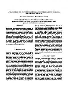
3.2 Traceability Dimensions for Software Product Lines From our review of existing traceability tools (Section 2), as well as existing SPL traceability propositions (Section 3.1), we conclude that there is still a need for a coherent and complete traceability classification scheme, to organize the different types of traceability links required in SPL development. In this paper, we define a set of orthogonal traceability dimensions to manage traceability in software product lines. The analysis is based on the traceability needs identified in the literature. We start by reusing the two traditional traceability dimensions. We then need a dimension to account for variability traceability as suggested by many. Finally, we believe that in software product lines, one needs tracing the evolution of artefacts (i.e., Software Configuration Management, see Section 5.4). Let us first summarize the four dimensions before discussing them in depth. Figure 2 illustrates examples of the four traceability dimensions. Refinement traceability: relates artefacts from different levels of abstraction in the software development process. It goes from an abstract artefact to more concrete artefacts that realize the first one. For example, a design model that refines a software requirement. Such links may happen in either of the two development stages of software product lines: domain engineering or application engineering.
Nicolas Anquetil et al.
Similarity traceability: links artefacts at the same level of abstraction. For example, UML components and class diagrams can specify the SPL architecture at different levels of detail but at the same level of abstraction (software design). The trace links defined between these artefacts can be used to understand how different classes, for example, are related to specific components (or interfaces) of the SPL architecture. The links are inside either of the two software product lines’ processes: domain engineering or application engineering. Variability traceability: relates two artefacts as a direct consequence of variability management. For example, at the domain engineering level, a variability traceability link would relate a variant with the artefact that “realizes” (or implements) it. Or, an application artefact (application engineering level) would be related to its underlying reusable artefact at the domain engineering level. For example, a use case model and a feature model can be related to illustrate which functional requirements are responsible to address the SPL common and variable features. Such traceability links allow understanding how SPL features are materialized in requirements and find potential related candidates during a maintenance task. Versioning traceability: links two successive versions of an artefact. Table 3 summarizes information on these four traceability dimensions. The variability and versioning traceability dimensions are the least common ones. So, let’s discuss them in more detail. 3.2.1 Variability Traceability Dimension. As proposed by Pohl et al. [45] there are two main types of variability traceability links. One could see them as subcategories in this dimension. The first relates a variant in the variability model (therefore at the domain engineering level) to the artefacts that realize it, at all stages of the SPL development. Following Pohl et al. definition [45, p.83], we will call it realization. Although it is restricted to one process (domain engineering), it is different from refinement because: (1) it is a direct consequence of explicit variability management, whereas refinement traceability exists in traditional software engineering and therefore has no direct relationship to variability; (2) it does not stem from the activities of the development process where one lowers progressively the level of abstraction of the artefacts produced; rather, it shows which SPL parts should be included or considered in a particular application if the variant is selected. This subcategory of variability traceability is used in [7] and [38]. The second subcategory relates an artefact in the application to its underlying reusable artefact in the family. We propose to call this relationship use, because the application (product) actually uses a reusable artefact defined in the application family (product line). It is not a
A Model-Driven Traceability Framework for Software Product Lines
7
Fig. 2 Examples of the four orthogonal traceability dimensions (grey arrows) in the two processes of a software product line.
Table 3 Some information on the four traceability dimensions. Dimension Refinement Similarity Variability/Realization Variability/Use Versioning
Occurs in which SPL engineering process? Domain or Application Engineering Domain or Application Engineering Domain Engineering Application Engineering to Domain Engineering Domain or Application Engineering
refinement traceability either because: (1) it crosses the boundaries of software processes, and relates an artefact at the application engineering level to another artefact at the domain engineering level; (2) one artefact is not less abstract than the other; actually, they are the “same” artefact, one defined in the application family, the other reused in the application. This relationship is identified by Pohl et al. but does not seem to have been used in other work. The use traceability relationship can be derived from the realization, but the opposite is generally not true. The reason to consider it as a useful relationship is that computing it on-the-fly would be too expensive and several important trace functionalities are easily defined using this relation. 3.2.2 Versioning Traceability Dimension. Software Configuration Management (SCM) is an important issue in software product lines, as one product family will include concurrent applications from different stages (or ages) of the whole family. All these applications are related to the same family and therefore are derived from the same set of artefacts. Artefacts may evolve concurrently both at the application engineering level (in any of the applications) or at the domain engineering level. Traceability is actually a central part of Software Configuration Management systems [13, 39]. As the artefacts stored in the SCM system evolve, the system itself is able to trace the evolution of single artefacts. In addi-
tion, SCM systems are used for building configurations (baselines), for example as the basis for product deployments. In general, SCM systems hold the possibility to group versioned elements into any meaningful unit. The information on the configurations provides traceability into the different parts of the development process where these configurations are used. However, SCM systems, such as, Subversion [11] and Microsoft Visual SourceSafe [35], are limited to tracing the evolution of files. These systems are either not at all concerned with the dependencies that arise between the stored files and other artefacts in a software engineering process, or only to a limited degree. Visual SourceSafe, for example, allows to trace which files are used across multiple projects, i.e., tracing the reuse of software components or implementation elements, but they do not provide support to trace requirements or specific SPL features. Information of such interdependencies between artefacts can be captured using traceability systems/tools. However, these systems/tools are not concerned with the integration of versioning information. The importance of integration between SCM and traceability tools is also recognized in [39] as cited in Section 3.1. The integration between SCM and traceability systems must be considered in both directions. Either system can benefit from the information provided by the
8
other. The following two key scenarios demonstrate the usage of integrated information. The first scenario is to use traceability information provided by the SCM system for enhanced impact analysis. This is especially important during software maintenance. In such scenario, errors must be corrected; traceability in the versioning dimension can be used for impact analysis regarding the other versions of a product that must be corrected. In software product line engineering, the complexity of this impact analysis is enhanced even further as also other members of the product line and their respective versions must be identified using the impact analysis. The second scenario is to aid the construction of baselines, which is one of the major responsibilities of SCM systems. Baselines are configurations of artefacts that are, for example, a beta release, a stable release, or a release delivered to customers. By using backward traceability information, this process may be enhanced with information regarding implemented requirements or included features. Thus, developers are able to determine the correctness and consistency of the baselines. The traceability information that stems from the baselines is very important during product line maintenance. The additional traceability information, that relates the artefacts in the versions as they were used for a release, may be used to recover the state of the software that was delivered to the customer. Traceability information regarding implemented features of the product line can be retrieved and, thus, provide a higher level of understanding regarding the specific baseline.
4 A Model-Driven Traceability Framework to SPL Our goal is to implement a traceability framework that accepts the four dimensions of traceability. However, there is a number of additional requirements that this framework should respect. This section reviews these requirements, then describes the metamodel designed to answer them and from which the traceability framework will be built.
4.1 Traceability Framework Requirements Traceability still faces many challenges in software product line engineering, in particular, the heterogeneity and number of artefacts, the increased complexity of artefacts, and the diversity of software processes. Most current tool support is too specific to deal with these new challenges (see Section 2). For example, commercial tools do not deal with new artefacts [13] and abstractions, such as variability points and variants, or they do not easily inter-operate with other tools [1], such as feature
Nicolas Anquetil et al.
models. Although we focus here only on technical problems, there are also social, communication and economic problems involved that will need to be tackled. In a study of the factors influencing traceability adoption, Ramesh [47] identifies two main groups of traceability users, low-end (who are not using or only started to use traceability) and high-end (who have been using traceability for at least five years), which have different objectives and practices. This paper describes four factors for adopting and using traceability: (i) develop methods, (ii) acquire tools, (iii) develop tool, and (iv) change system development policies. Acquire tools and develop tools are the most relevant factors to our current task on traceability tool support. Mohan and Ramesh [38] also present key recommendations for successful traceability of variations. From the technical perspective, we can note their recommendations: focus the documentation on variation points, provide an integrated environment, and propose a comprehensive traceability solution. From these indications, we decided to develop our own traceability framework. Therefore, this framework must attend to a number of requirements that we found important: – it should be process agnostic, not imposing any artefact or link type; – it should be flexible, for example by allowing easy incorporation of new artefact types or link types; – it should be scalable and deal with real life software product line; – it should be extensible, allowing the creation of new ways to register, retrieve, manipulate and otherwise manage the traceability links; – it should support m-to-n traceability links, as opposed to only 1-to-1 links, that most of the existing tools work on. Being process agnostic is a fundamental requirement of any traceability tool [13]. There are too much different processes, each with specific artefact types to commit with such an early decision on this issue. Except for the work of Moon and Chae [40], all other approaches seem to have a predefined set of artefacts types which cannot be adapted to other development contexts or user needs. Furthermore, according to Ramesh and Jarke [48] allowing an hierarchy of artefact types is useful to tune the granularity level of the trace. The same goes with link types. We therefore need to accept creation of new kinds of artefact types and link types, these being possibly organized in hierarchies of types. Flexibility is required to ensure that new artefact or link types will easily be created. For example, if Moon and Chae [40] need to create new types of artefacts, they need to modify their metamodel, which is not an easy task. We need a solution where new artefact and link types can be created, if possible directly in the repository framework. Considering the different traceability
A Model-Driven Traceability Framework for Software Product Lines
9
dimensions encountered in SPL development, this need for flexibility is still more critical.
4.2 Traceability Framework Metamodel
Regarding scalability, we saw in Section 2 that commercial tools do not deal with software product line engineering. Unfortunately, most of the research tools only accept toy examples. Although we do not aim at competing with the commercial tools, the presence of industrial partners on the AMPLE project makes it an obligation for us to come with solutions that have some relevance to them. This includes being able to deal with hundreds of thousands of artefacts and links. For example, several approaches or tools are using an XML support to document and/or trace links (e.g., [26, 49]). There have been concerns in the past on whether XML scales up nicely or not (e.g., [34]). In need for a definite answer, we decided to store the data in a relational database.
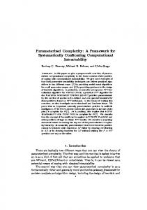
From the previous requirements, we elaborate a metamodel for traceability links. The goal of the metamodel in our traceability framework is to provide a uniform and reusable structure for defining trace models during software product line development. We studied some of the existing traceability metamodels of the literature. One important piece of inspiration was the ModelWare traceability metamodel [46]. We reuse the idea that the model must be as simple as possible and the complex logic for analysis shifted to the tool support. There exists a large body of knowledge related to metamodels for traceability [3, 4, 9, 10, 16, 19, 26, 28, 48,49,55]. A variety of approaches for storing traceability information are proposed: database schema [6], XML schema [26, 49] or metamodels [19, 28, 46]. We choose an agnostic metamodel representation since we want to address traceability when aspect-orientation, model-driven development and software product line engineering are used in conjunction. We said that we want the user to be able to define the kinds of artefacts or links he needs. Thus, the metamodel must represent not only artefacts and links but also kinds of artefacts and kinds of links. These types can be organized in hierarchies. Another point is that we want to deal with m-to-n links, that is to say, with possibly multiple sources and multiples targets. Our framework must be configured before usage, what implies taking into account additional constraints. For instance, a user may need to define a kind of link, say UC-refinement, which is only existing between a use case and an UML sequence diagram. Thus, we introduce the notion of scope and scope area to cope with this additional constraint. As in [33], we consider that many information can be attached to artefacts and links. Our information system must be sufficiently rich to represent information related to the tracing context, for instance rationale for design decisions, variant choices or other information. Thus, we provide the concepts of artefacts and links with a dictionary of properties and so-called context objects that might serve as a container for more complex information. The metamodel for traceability is depicted in Figure 3. This metamodel is designed in MOF 2.0 [42], as it facilitates the integration of tools and languages developed in AMPLE by providing easy mapping/transformation to Ecore metamodel from Eclipse Modeling Framework (EMF). EMF is the model-driven framework that was adopted to implement our traceability framework. This traceability metamodel basically defines TraceableArtefacts and TraceLinks between these artefacts as fundamental elements. The TraceableArtefacts are references to actual artefacts that live in some kind of source or target model or just arbitrary elements created during the development phases of an application like, a requirement in a requirements document. Such
The traceability framework should also be easily extended to adapt to new needs, such as creating new queries, new ways to visualize the results, and interoperate with other existing tools. Again, a solution like the one proposed by Moon and Chae [40], where a metamodel needs to be modified to change the framework, does not answer our requirements. We would rather favor a solution that allows “traditional” (non MDE) programming extension. MDE is still not widely used in many real world settings and we feel that imposing it to the user of our framework could create a barrier to its adoption. This does not mean we rule out MDE. Actually, there seems to be a general tendency to use MDE for traceability tool support ([1,19,28, 40]). We believe that MDE provides flexibility and easier evolution management for the framework. Therefore, we will adopt it. Nonetheless, we do not want to impose the use of MDE to the user of our framework as this technology is not always a practical solution in real world environments. Finally, dealing with m-to-n traceability links was set as one of our goals. M-to-n links are required as recognized in Pohl et al. [45, p.70] or Berg et al. [7], however, from the evidences published, it seems that all research — including Berg et al. [7] — only deals with 1-to-1 traceability links. If m-to-n links are more difficult to represent graphically (see Section 5.3.3), they allow to represent more accurately the reality of the traceability links, particularly links such as refinement traceability. In case of SPL development, these kinds of links can contribute: (i) to reduce the total amount of trace links, thus helping the tool scalability; and (ii) to represent more concisely a set of trace links between variability (variation point, variants) and its respective artefacts related to it in the application engineering. When representing the causality between, for example, a requirement and several design artefacts, it is important to know all the design artefacts that stem jointly from the same requirement so as to understand them jointly. Representing mto-n links also diminish drastically the number of required links and therefore simplifies the representation.
10
traceable artefacts are named elements that contain, in addition, an URI, that denotes the location of the actual element and the way to access it (e.g., a text document, an UML model, an elements inside an UML model, etc.). An example for such an URI could be prj://crm/models/datamodel.ecore/Customer, denoting a model element Customer in a model datamodel in the folder models of a project crm that is made accessible from some company-wide project repository denoted by the URI protocol prj. A traceable artefact in the repository can play the role of source artefact and target artefact, simultaneously. For instance, an architectural artefact could be a target traceable artefact when considering a requirements to architecture mapping, and a source traceable artefact when considering an architecture to implementation mapping.
Fig. 3 The ATF Traceability Metamodel.
A TraceLink represents explicitly trace relationships between a set of source artefacts and set of target artefacts. This enables the management of traceability models as a set of annotated, directed, bi-partite hypergraphs G = (V1 + V2 , E), where V1 is the set of source artefacts, V2 is the set of target artefacts, and E is a set of annotated arcs from P(V1 ) to P(V2 ). The annotations serve to distinguish different kinds of relationships between source and target elements. To allow a more fine-grained control of the traceability relationships, hyperlinks can also be decomposed into a set of traceability links, which represents a relationship (e.g., a dependency) between one source artefact and one target artefact. Each TraceableArtefact and each TraceLink is typed to denote the semantics of the element itself. This type is expressed via a TraceableArtefactType and a TraceLinkType, respectively. Each type exists exactly once in the appropriate domain. However, a type is not a singularity within such a domain, instead it may share aspects with other types. For this reason, types may form an inheritance hierarchy. An example would be an
Nicolas Anquetil et al.
UML Diagram type, which can be specialized into a derived UML Sequence Diagram type. Derived types share properties with their parent types, just like classes in object-oriented languages. Multiple inheritance is possible to generalize this concept. Defining a type hierarchy enables generalized reasoning over trace data, i.e., taking UML diagrams into account, regardless whether they are sequence or activity diagrams (given the appropriate type for sequence and activity diagrams are defined as subtypes derived from a UML diagram type). Links between artefacts can be established in an arbitrary manner. However, for a domain, this is usually not desirable, as particular links of a certain type only make sense as relationships between artefacts of certain types. For example, a UML Classifier may not contain an UML Class Diagram, while the opposite is of course valid. To allow such consistency checks, the so-called Scopes and ScopeAreas have been introduced. Each TraceLinkType has one scope, in which it is valid. The scope itself contains a number of scope areas. A scope area defines which artefact types are allowed as types for link source and link targets. In order to ease the creation of such validity scopes for link types, these types derive their scope from their base types according to the inheritance hierarchy explained in the previous paragraph. Artefacts and links form a graph which represents the relations between elements that are produced during the development of some arbitrary software product. However, knowledge about these relations alone is most probably not sufficient during the reasoning process over the trace graph. For this reason all elements of the trace graph may be annotated with additional information. The most simple way of annotating elements is by using key-value pairs. Appropriate keys and values may be created for each artefact and link (and also for types). As an example, the creator and the creation date of some model may be attached to the artefact referencing this model. A creation date may also be attached to some link of type transforms to to denote the point of time at a model transformation has taken place. However, we are aware that simple key-value pairs may be used to capture additional trace information, but using this possibility only may not be sufficient in some cases. For this reason each element in the trace graph may reference an optional TraceContext. This is a nothing else than an empty element in the metamodel from which a user can derive and extend the metamodel appropriately. This way, arbitrary complex information can be attached to elements in the trace graph, like the context in which artefacts have been created and relations among them are valid (just as the name indicates). Our metamodel is very similar to the one proposed by Walderhaug et al. [55]. Both have traceable artefacts and traceable artefact types, what we call trace links and trace link types are relation traces and relation trace types in Walderhaug et al.. Three differences stand out. First, our scope is more general than the mechanism pro-
A Model-Driven Traceability Framework for Software Product Lines
posed by Walderhaug et al. that allows only one type of traceable artefact as source of a trace link type and one type of traceable artefact as target. Second, Walderhaug et al. propose an artefact trace that appears to allow automatic trigger of actions when traces are created. Finally, we allow representing the context of a trace or an artefact to register such things as a design rationale for example.
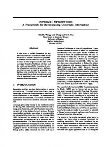
5 The Framework The overall design of the ATF framework is depicted in Figure 4. We built it as an extension to the Eclipse framework. This gives us a strong platform on which to build our tools and it is a good solution to allow easy integration in a typical working place. The core part of our ATF framework is the traceability information system which is based on a metamodel (see Section 4.2) and a repository (see Section 5.1). The front-end of ATF, in Section 5.2, allows the user to interact more friendly with the core ATF and define procedures and extension points to add new facilities to the framework. Different extensions to the framework started to be implemented, some of which will be introduced in Section 6. Finally, one important piece is the interaction with the configuration management system which provides for versioning traceability. This is described in Section 5.4.
Fig. 4 Overall ATF Design
5.1 ATF Core The core of the framework is centred around the metamodel described in Section 4.2. The core consists of func-
11
tionality to initialize the framework and to grant access to the contained trace data. The trace data is held in a trace repository, which contains all the specific data necessary to a certain use case for tracing activities. In particular, it contains: a set of artefact and link types, as well as their allowed relationships among each other (in form of scope and scope areas as explained at the end of Section 4.2); artefacts and links as relations between more appropriate properties; and, context objects that form the rationale for the existence of all trace elements. The main entrance point(s) to the framework is a set of manager classes. Each trace repository is controlled by a so-called RepositoryManager, which grants access to other managers tailored to various facets of the work with such a repository. Namely these are a PersistanceManager, a TypeManager, an ItemManager, an ExtractionManager and a QueryManager, providing functionality for common tasks and shielding the framework from unintended misuse, that may jeopardize the consistency of the stored trace information. Besides, tasks of a RepositoryManager include the establishment and the closure of a connection to a repository, configuration of the persistence and the initialization of the repository with default content (namely predefined artefact and link types that are relevant to the respective trace domain). The latter is done via so-called repository profiles, which are basically XML files which contain artefact and link types and their appropriate scopes, which define their validity area. A profile can be set up in an arbitrary way and reflects the hierarchy of artefact/link types available for a certain trace domain. For instance a user can define a profile containing two abstract top-level link types horizontal and vertical and define other relevant types as derived subtypes, i.e. depends on may be derived from horizontal, while is transformed to may be derived from vertical. The type depends on itself could be refined again by some other type. The profile allows to set up type hierarchies like this in a convenient way, as well as to define predefined properties for artefacts/links of certain types. Such profiles can be reused or merged from case to case to match the requirements of a new domain. The PersistanceManager is responsible for persistent storage of trace information, which allows CRUD (Create, Read, Update, Delete) operations on trace data. The ATF comes with two implementations: one using EMF/Teneo which allows trace data to be stored in relational databases like MySQL, and one which saves information into plain XML files. If scalability is important, one should only use the relational database option. Users with special needs for persistence may also create their own persistence managers, which can be plugged into the framework via an extension point. New types and items are created via the TypeManager and ItemManager, respectively. While the first just provides the same functionality for creating and
12
configuring new types as one may also express via the information contained in a repository profile, the latter offers many convenient methods for creating, updating and removing artefacts and their relations, while performing permanent sanity and consistency checking. Creating and updating trace information is only one side of the story; accessing the information in a certain manner is the other. The QueryManager provides access to the stored information. According to the metamodel presented in the previous section, artefacts and links are not contained in any specific data structure. This is due to scalability reasons. In a real-world application for the ATF, the repository would contain millions of artefacts. Initializing the container structure for the artefacts would result in constructing objects for all stored artefacts in memory — which will fail at a certain number of objects. In addition, it is unlikely that a user has to work with all artefacts and links at the same time. Rather, a user needs only access to artefacts/links with certain properties — and the QueryManager allows access to them in an appropriate way. It allows a user to create basic queries, submit them to the underlying data store and construct the artefacts in memory. Referenced artefacts/links are loaded from the data store on demand. Queries themselves are built from constraints, which can be concatenated with Boolean operators. Thus, a user might query the repository for all artefacts of type X whose name start with ’abc’ and have at least one outgoing link of type Y. The query manager is intended to be the basis for an advanced query module (see also next section), which allows a user to formulate more complex queries that are compiled into a set of simple queries by using the possibilities of the query manager. Such advanced query module would be tailored to special traceability scenarios and is subject to future work. For now, there are about 25 different constraints from which queries can be built from. Trace information must be recovered from certain information sources. Depending on the nature of these information sources, small modules can be defined which actively mine for trace data. These modules are called trace extractors, in the ATF context. Controlling the lifecycle of such extractors is the responsibility of the ExtractionManager. Extractors can be developed as independent components that might be (re)used on byproject basis. They can be registered to a repository, appropriately configured, and run via the extraction manager. New, user-created extractors can be plugged into the framework via appropriate extension points. The functionality of the core of the ATF was carefully designed to be generic and easy to use. Actual applications dealing with certain traceability scenarios are built, or instantiated, on top of the ATF core, as explained in the next section.
Nicolas Anquetil et al.
5.2 ATF Front-end The ATF front-end aims at providing an open and flexible GUI platform to design and implement new tools and methods to define and manage the trace information residing in an ATF repository. This front-end uses and extends the services provided by the ATF Core and can be seen as a high-level API for managing and querying the trace information stored in ATF.
Fig. 5 ATF Front-end Architectural Overview
Figure 5 illustrates an architectural overview of the ATF front-end. This has three main hotspots (Trace Register, Trace Query and Trace View) that can be instantiated to provide the desired trace mechanisms. The main objective of the front-end is to provide some glue between these hotspots, according to the general workflow illustrated in Figure 6. With the front-end and a series of basic plugins already implemented (see Section 6), a developer can add specific capacities, for example a complex query, without having to worry about anything else, for example how to visualize the result. A Trace Register instance is similar to the ExtractionManager in the core. It provides support to create new artefacts and links in the repository. This is done by adding plugins that could use fully automatic techniques, provide a GUI for manual definition of the trace information, or a combination of both. A Trace Query instance provides means to perform specific (advanced) queries on a set of trace links and artefacts. It uses the ATF basic query capabilities to execute more complex and powerful queries (e.g., feature interaction detection and change impact analysis). Finally, Trace View instances are responsible for supplying some sort of view (graphical, textual, etc.) for the results returned by the execution of a trace query. The front-end UI allows defining Traceability Scenarios. A scenario can be used to group registers, queries and views that are related in some logical manner. For instance, to group all the queries and views related to the variability dimension in order to perform a variability analysis of the product line. The Extensions Loader module is responsible for detecting any hotspot instance and make it available to the user in the appropriate in-
A Model-Driven Traceability Framework for Software Product Lines
terface. This simplifies the process of integrating new instantiations to the existing framework. Finally, the Generic Viewers and Editors module is used to provide a “black box” instantiation environment. This relieves the burden of instantiating an hotspot, has a developer will not be required to be aware of the underlying mechanisms (e.g., implementing graphical components). Figure 6 depicts the workflow of this framework. The idea is to begin by creating an ATF repository, and populate it using either the appropriate Trace Register or the core ExtractionManager. It is then possible to execute a Trace Query instance and pass the results to the desired Trace View instance. The user can further refine the query results by executing a new query, which will return a refined set of trace links or artefacts, until the desired information is reached. The idea is to perform a round-trip between the queries and the views. The query results are passed to a view, which in turn allows the user to select a set of trace links or artefacts and execute a new query with that selection. The results may also be exported to several formats, using special views for that purpose.
Fig. 6 ATF Framework Workflow
13
traceability scenario and rely on the framework to provide infrastructure and needed additional facilities. 5.3.1 Register Plugins. Register plugins introduces new artefacts and links in the repository. The artefact and link types must have been created before inserting the data. We implemented several of such plugins on different types of data: – Populating from various kinds of development artefacts. Plugin extractors were developed for importing artefacts or models produced by tools such as, Rational Rose, Enterprise Architect, MoPLine, or Eclipse Feature Modelling Plugin (FMP). They are used to extract various kinds of artefacts such as use cases, actors, class diagrams, features models. These plugins would be mostly useful for Refinement or Similarity traceability links. – Populating from source code. We have also implemented two independent Java extractors: one using the JavaCC parser, and the other using Eclipse JDT (Java Development Tools). Various levels of granularity of artefacts may be looked for in source code, such as packages, files, classes, methods or even statements. These plugins would be mostly useful for Refinement or Similarity traceability links. – Populating from MDE process. Members of the AMPLE project defined two concurrent MDE tool chains that produce traceability data in XML format. Extractors were defined that process these files to load the data in the repository. These plugins concentrate on Refinement or Similarity traceability links. – Populating from source configuration system. We defined a plugin that interact with a Subversion server to extract software configuration information. This plugin concentrates on Versioning traceability links and will be described in detail in Section 5.4. – Manually populating the repository. One plugin allows to manually define links between already registered artefacts. This is intended to complement the other plugins by providing information that could not be extracted automatically.
5.3 ATF Plugins We have implemented a number of plugins that extend the basic functionalities of the framework. These experiments confirmed some of our choices and demonstrated the flexibility of the ATF. ATF plugins are standard Eclipse plugins that may extend the ATF in three directions (see also Section 5.2): Trace Register, to populate a repository; Trace Query, to implement complex advanced queries that should be of interest to end-users (e.g., impact analysis); Trace View, to visualize the result of a query. These plugins were developed independently, by different members of the AMPLE project. Anyone can implement a plugin of interest to address his/her specific
5.3.2 Query Plugins. Query plugins allow extracting information from the repository. It is intended to implement advanced queries that should be of interest to end-users. We have two such advanced queries: – An impact analysis query that uses transitive closure on forward refinement traceability links to define all the artefacts potentially impacted by a change in one (usually abstract) artefact. – A feature interaction query that also uses transitive closure on forward refinement traceability links to identify pairs of features that could present interaction issues. This happens when the intersection of the transitive closure of the two features is not empty.
14
5.3.3 View Plugins. View plugins allow to visualize the result of the queries. To visualize trace link graphs is valuable, at least as an exploratory aid [25]. As in [33] we agree that visualizing traceability links is important, but getting a useful view is a non trivial task. This is particularly the case for us since we use m-to-n links. For example, the realization traceability link may relate one software requirement to several design artefacts, all packaged in one or two components. Graph visualization is an old preoccupation of computer science. There are many tools available, for instance, graphviz [18], prefuse [23] and jung [53]. One challenge is visualizing a huge quantity of data. It requires specific tools such as those proposed in [41]. To solve the scalability issue, abstraction and clustering techniques (see [22]) are helpful. We explored different ways to visualize the trace links and will discuss this basic support here. We feel that more advanced support is the responsibility of the information and visualization community. Because of the m-to-n links, trace information forms an hypergraph, a graph where links may relate more than two vertices [8, 21]. Although graphs have a very natural and intuitive graphical representation (points linked by lines), hypergraphs may be more challenging. Unfortunately, there are few tools to represent and manipulate hypergraphs. We identified three possible representations for traceability links: – represente hyper-edges as arrows with more than one source or/and more than one target. This is the most intuitive solution, but it is complex to render graphically, especially when there are many vertices scattered over the surface. We did not experiment this possibility. – use “sets” to represent the links, where one such set includes all the vertices which are either source or target of an hyper-edge. This is similar to a Venn Diagram [54]. It can look cluttered and directed edges (which traceability links are) are not easy to represent. We experimented this solution but will not illustrate it here. – promote the links to new kinds of vertices turning the hypergraph into a bipartite graph: a graph with two different kinds of vertices, and vertices of one kind are only related to vertices of the other kind. It is visually less intuitive as one needs to identify “true” vertices, the artefacts, and “false” ones, the links. However, it suffers less from the problem of scattered vertices than the first solution and can represent directed edges. Another benefit is to be able to use the numerous tools, measures and theory that exist for bipartite graphs. Two examples of such representation are presented in figures 10 and 11. We also experimented with non-graph representation:
Nicolas Anquetil et al.
– Textual list of links, useful to export to a file or when there are many links. – Textual hierarchical representation where the artefacts and the links are unfolded on user demand (see Figure 8, for an example). It does not allow a global view of the links but provides a good and simple way to explore and navigate the graph. – Graphical hierarchical representation (see Figure 7), conceptually very similar to the previous one, but possibly more intuitive to interpret. 5.3.4 Future Extensions. We are still working on ATF plugins to extend its capabilities. Two main exploration directions are envisioned: advanced queries and visualization. First we plan to implement more advanced queries that would solve concrete problems. Such problems may include, for example: Test case coverage — to check that a feature is covered by at least one test case; Dead code identification — to check whether a given software component is actually related to some high level artefact (e.g., a SPL requirement, feature or variability); Correction back-porting — to find all the versions of a changed artefact in all generated SPL applications; MDE debugging — to identify the source of an error in the generation process. Another exploration direction would be to try to improve the visualization of the links. One possibility we are interested in would be to take advantage of the orthogonal traceability dimensions to show four views of a given set of links according to the four dimensions. Two proposals are envisioned: the first one would be similar to what we currently have (graphical representations of the links) and one could turn on or off the drawing of particular traceability dimensions to simplify the graph; the second one would offer four connected views where the artefacts would have the same position, but each view would present the links in one traceability dimension.
5.4 SCM Integration in ATF One of the plugins implemented is dedicated to realize the integration of software configuration management with the traceability framework, so as to deal with the forth traceability dimension (Versioning traceability). Although SCM and traceability are two relatively well understood activities of software development, their integration is not completely trivial and need to be discussed here. The primary aspect of traceability that is enabled by SCM systems is the traceability of the evolution of versioned items. Items inside the SCM system are subject to evolution through revisions. To represent the evolution of versioned items, the version set is often organized in a version graph, whose nodes and edges correspond to versions and their relationships, respectively.
A Model-Driven Traceability Framework for Software Product Lines
15
Fig. 7 Screen Shot of the ATF Tree View
In general, there are two choices to represent integrated information between an SCM system and a traceability system. Either the elements of the SCM system become first-class citizens in the traceability system, e.g., nodes in a traceability graph, or SCM information is represented as metadata of specific traceability entities, e.g., a property which states that a traced element corresponds to a certain file and revision in the SCM system. The first approach can result in increased size for the data in the traceability system, because not all changes in an artefact must have corresponding changes in the traceability links. Thus, we have several traced elements with the same traceability links. However, the approach also provides a uniform way to query all dimensions of traceability in one coherent framework. The second approach can reduce the size of the traceability data, but it requires more elaborated synchronization and querying mechanisms. Synchronization is an issue if a sequence of versioned items has the same traceability links, e.g., version 1 to 5 of an artefact. In this case, the integration must provide ways to represent this in the metadata. In addition, the query mechanisms must be more elaborated to examine this metadata and correlate the trace links that are represented in the SCM system to the traceability information. We have chosen the first approach and elected to make SCM items first-class citizens of ATF. The information residing in the SCM system is made available to ATF through extractors. Once the information is stored in ATF, traceability links can be established to specific versions of artefacts. An extractor for the Subversion system was implemented as a proof-of-concept [36]. Since ATF now includes different versions for artefacts in the traceability graph, new trace links between artefacts must be specified by using the respective artefact versioning information. Without the version infor-
mation, the ATF cannot decide for which versions the link is applicable and relies on a default policy that decides this applicability. Such a policy can be, for example, that the link is always provided for the latest version of an item. The integration of SCM information as first class citizens offers many benefits. Firstly, the approach allows an easy correlation of the information from different SCM systems, by providing one integrated view of the information. Thus, the approach offers the possibility to incorporate heterogeneous tools landscapes used during the software engineering process. Secondly, repositories can also come from different vendors and use different versioning schemes. For example, Subversion uses a global versioning scheme, while CVS has independent versions for each item. Both systems can be represented using an ATF integration. Finally, the approach allows providing versioning schemas for fine-grained traceability items that are usually not considered in SCM. As part of the AMPLE project, we have implemented a feature-driven versioning approach, that versions feature models in software product lines. The feature-driven versioning allows to correlate versions of features with versions of artefacts in SCM and with versions of products. Thus, enhanced traceability of variability in the product derivation is provided. This incorporates (i) traceability of variation points, i.e., features, into instantiations of components and (ii) traceability of these instantiated components into the products.
6 ATF Instantiation This section presents an instantiation example of the framework. The example is part of the reference instantiation that was created for the AMPLE project. It describes end-to-end traceability from market requirements
16
to code, and includes product line features and UML models. ATF is a general purpose traceability framework and can be configured to suit many different projects and traceability scenarios. Thus, in the following, we describe the process of instantiating the ATF framework for a specific software product line scenario. The example comes from the Smart Home application domain, an “intelligent” home where doors, lights, entertainment, security, . . . are all controlled and integrated by computer. Our smart home example will use rooms, two optional features (security and automatic window), lights and light controllers, and security devices, such as burglar alarms or presence detectors. Initial requirements are grouped into common and variable features, which determines the feature model. The requirements are documented by scenarios, which are described with UML sequence diagrams, at design level, and further implemented in test cases. The feature model, with the help of scenarios, is designed into a UML class diagram which will be implemented by Java classes. For simplification purposes, as part of the MDE process, we suppose one builder “script” (or transformation) that automates the generation of applications.
Nicolas Anquetil et al.
ability dimensions proposed in Section 3. We did not consider Similarity links in this small example.
6.1 Analyzing the Software Product Line Process The first step to instantiate the framework is to define which artefacts are needed and how they relate to one another. In our example, we use a simplified process and we assume the following steps: (i) Requirements Engineering, (ii) Variability Management, (iii) UML Design, and (iv) Implementation. Another important issue is the granularity of the data, or the degree of detail and precision in traced artefacts. The extremes in the spectrum of granularity are a large number of narrow categories, or a smaller number of broad categories. The choice of granularity must be governed by the kind of analysis to perform. For example, for a requirements coverage analysis one would need traceability for individual requirements and the artefacts that realize them. In this example, we use a multi-layered granularity approach. Mohan et al. advocate that such a traceability plan is essential for effective change management [39]. The artefacts include high level ones such as an entire requirements document but also individual elements contained in such artefacts, such as individual requirements. From this, we defined a repository with the necessary artefact and link types. This definition could be done either using the XML profile or the ATF programming interface. Figure 8 illustrates a view of the two hierarchies of types (artefact and link types). It presents the different artefacts and link types that are part of our software product line process to support traceability. As we can see, the high level link types are the four trace-
Fig. 8 Example Instance of ATF metamodel
6.2 Traceability Scenarios In software product line engineering, Domain Engineering is responsible, among other things, for: (i) the analysis and identification of the commonalities and variabilities typically specified in the feature model; and (ii) the specification and implementation of a SPL architecture that addresses these common and variable features, which can be, for example, modeled using a combination of UML diagrams (used to represent its components and relationships), and implemented using Java components. During the domain engineering process, different artefacts (feature models, class diagrams, Java classes/interface) can be elaborated and traceability links must be created between them to allow a better management of variability and change impact analysis. Suppose we want to build a house with one room and the optional security feature. Later we get a new market opportunity which considers that automatic windows are also an interesting feature option for a room. Figure 9 gives a view of this simple feature model with the Roomfeature and two optional (Securityfeature
A Model-Driven Traceability Framework for Software Product Lines
17
and Automaticwindowfeature) sub features. The design was elaborated using the FMP plugin available at http://gsd.uwaterloo.ca/projects/fmp-plugin/.
Fig. 9 Simple (FMP) Feature Model
First we need to perform domain engineering and to build two applications corresponding to a simple room and a room with security. After application engineering, we get an initial trace set, which is depicted in Figure 10 (top part). This view represents the artefacts created and the Refinement links between them from domain and application engineering. Variability and Versioning links do not appear in the picture. Figure 10 also shows a bipartite graph approach to traceability link visualization (see Section 5.3); the large nodes represent the artefacts and the small ones represent the links. Links and artefacts are selectable in this view and when one is selected, its properties (name, type, identifier) appear in the top part of the graph (grey background). In top part of Figure 10, the feature model artefact is selected (it is indicated by a bold arrow, at the right hand side of the graph). When an artefact is selected (node 14 on the far right), the links stemming from it are in light red, and the target artefacts of these links are pink colored (the eight nodes in darker grey). The bottom part of the figure enlarges a part of this graph with the selected artefact (bottom right) a link from it (called implements, a link type from the Refinement dimension), and several target artefacts (e.g., the UML class diagram and the UML light controller class). The developers need to test this new application, so they use the trace set repository to find the set of test cases applicable to the SmartHome product line. The steps to find these test cases could be: 1. Start from the product configuration (also called a feature model instance) that represents a specific SPL product/application derived from a selection of variable features in the SPL feature model; 2. Compute the requirements included in the product from this configuration and the realization links (Variability dimension) in the product family; 3. Compute the transitive closure of Refinement links in the domain engineering to find out all the test cases associated to these requirements. If the procedure needs to be repeated frequently, one could imagine automating it with a new Trace Query
Fig. 10 View of the Initial Trace Set (top part) and enlarged view of some nodes (bottom part)
plugin. The following excerpt of Java code illustrates how the query could be programmed: Query qLinks = qm.queryOnLinks(); qLinks.add( Constraints.type(tm.findLinkTypeByName("uses"))); List result = new List(); for (List lnk : qLinks.execute()) { //test source name and target type if (... && ...) {result.add(lnk);} }
An empty query is first created from qm, a QueryManager instance (see Section 5.1). Then one adds the constraints to this query; here we constrain on the type of link (uses type) that we want to use. Finally, a loop on the result allows checking which of these links have the appropriate source or target. This is an example where the uses relation is useful for efficiently access to the artefacts associated to a product. Let us assume that during the tests, the burglar on test reveals that a requirement is missing: “light should
18
be switched on, on alarm”. A manual analysis of the system identifies that the Light Controller UML class does not capture the event alarm on. After correcting the problem, the developer uses the trace set to know what are the artefacts possibly impacted by this change. In this case, a view of the Refinement trace links in the “Radial view” plugin answers the questions. This is illustrated in Figure 11. In this view, one selects the artefact changed (here the UML light controller class identified by an arrow) which places it in the center of a semicircle with the related artefacts arranged in a semi-circle around it. Also, the links that stem from this artefact and the artefacts that are target of these links are colored in red (dark grey). The color is propagated recursively to the targets of the targets. Since the links visualized here are Refinement links, all coloured artefacts are those that derive from this UML class by refinement which gives us a simple impact analysis tool.
Nicolas Anquetil et al.
In our example, we should share our project and commit it. Following this commit, the first SVN registering will create an ATF representation of the artefacts in the project. As explained above, the developers have to add the required refinement links between these artefacts, possibly using some dedicated extractors, or manually. Continuing our scenario, the developers have to do some changes in the artefacts, changing some, adding others, etc. This leads to a new versioning action in the Subversion repository. Using again the SVN register, it updates the ATF artefacts and creates time links to denote versioning between artefacts. Introducing versioning increases the complexity of the representation and additional means to explore the links are needed. We have defined several algorithms computing sets of links which are useful to provide view points on the evolution of the product line. For instance, product derivation can be defined as the set of time and refinement links associated to an application. Similarly, product evolution is defined as the set of time and uses links related to a product. The results of these algorithms can be interactively explored using our predefined views. In Figure 12 we can observe that the two versions of the room with security application differ in four artefacts which have evolved due to the previous changes.
Fig. 11 Impacted Artefacts From Radial View.
6.3 Versioning Examples Versioning is an important companion of an ATF repository. The principle is to connect the development project with the Subversion system, for which we use the subclipse versioning system [51]. A specific extractor, the SVN register, has been defined to extract artefacts from a Subversion repository. This tool identifies new, versioned and deleted artefacts and it creates time links between the old and the new versions automatically. This tool has some other facilities, like managing coarsegrained and fine-grained artefacts, but this is out of the scope of this paper.
Fig. 12 Room with Security Product Evolution
In a further step we can also illustrate a change in the feature model. For instance, consider the extension of the feature model with the option for automatic window. The analysts, architects and developers modify the previous development project and commit it. The SVN register identifies 16 new and 25 versioned artefacts; this is a more complex modification of the software project
A Model-Driven Traceability Framework for Software Product Lines
19
than the previous change. At this step the feature model evolution is significant, its realization in artefacts and their evolutions. Figure 13 represents an interactive view of this graph complemented with some comments to help the reader. We can explore it to observe the structure of the feature model and the evolution of the realization of the features. For instance, the security feature has two realizations, while the room feature has two different versions.
Fig. 14 Two Products Comparison
7.1 Traceability Tools
Fig. 13 Feature Model Evolution
Other computations have been defined, like obtaining the refinement set of a product or the comparisons of two set of links. Figure 14 depicts the comparison of the refinement sets of the first version of the room with security application and the last version of the room with automatic window and security features. Green nodes (or links) are common to both products while violet are specific to the room with security, and yellow proper to the product with automatic window. This very simple example helps to understand how one could solve complex traceability problems using our framework and based on the four orthogonal traceability dimensions we identified.
7 Related Work
We already reviewed related tools in Section 2 and close related work in Section 3.1. However some other specific tools have not yet been discussed.
Mohan and Ramesh [37] present a traceability and knowledge management framework that supports tracing commonalities and variability in customer requirements to their corresponding design artefacts. The framework provides primitives to represent the conceptual elements, inputs and outputs of the system development process, as well as the links among them. The framework concentrates mainly on the identification of common and variable requirements, architectural design decisions and functional customizations done on the base product. The conceptual model identifies the various actors, documents and processes involved in the development process. Various dimensions of traceability information are exposed: what information, who are the stakeholders, how the information is represented and so on. These dimensions are very different from what we identified and are not limited to technical considerations. The traceability links are typed by predefined kinds which is also different from our flexible framework. Jirapanthong and Zisman [26] give several reasons to explain the difficulty of the traceability task in SPL (see Section 3.1). They use an extension of the Feature-based Object-oriented Method (FORM) [29]. Their approach relies on six groups of relations subdivided into nine different types of traceability relationship. The kernel of the system is a set of rules that are responsible for analyzing the documents and generate various traceability relationships between them. The rule based tool support seems a good way to automate the trace generation. In this approach, only classic object-oriented and UML artefacts are considered. It manages different types of artefacts and trace links but in an ad-hoc and unstructured way. Also, the set of artefacts and link types is not adaptable to other needs. The approach was refined and
20
extended in [27], to cover artefacts from a product line case study and a more detailed set of links. Asuncion et al. present an end-to-end traceability tool developed at Wonderware [5]. It supports the entire software development lifecycle by focusing on requirement traceability and process traceability. The authors discuss the following problems: multiple representations of the same document, obsolescence and distribution of documents, and multiplicity of individual processes in the company. Furthermore they quote additional issues: the manipulation of artefacts in bulk, the limited functionality of the commercial tool, the inability to scale, and the lack of effective trace visualization. They argue that technical, social and economic perspectives of traceability must be addressed simultaneously. In this paper we only consider technical issues. They propose a rigid traceability model that captures a set of common artefacts and the links between them. Our implementation authorizes a very flexible set of artefacts and trace link types. On the other hand, the workflow process seems more flexible. However, since the artefact types are frozen, this is not sufficient for an SPL approach. The design of the traceability tool is based on a threetiered client-server architecture: a data base support, a set of applications and an intranet layer for web access. Although we did not explicitly foster this architectural pattern, the organization is similar to our framework. The functionalities provided are: storing and management of traces, a visualization tool and MS-Word macros to support document automation. Apart from the SPL context, this paper exposes the same challenges that we observed. Two main differences can be pointed out, though: we propose a more flexible way to represent the software process information and we explicitly manage the software evolution in conjunction with traces.
Nicolas Anquetil et al.
clearly better; however it needs to identify uniquely each artefact, even fined-grained artefacts. Much of the recent research has focused on finding means to automate the creation and maintenance of trace information. Text mining, information retrieval and analysis of trace links techniques have been successfully applied. An important challenge is to maintain links consistency while artefacts are evolving. In this case, the main difficulty comes from the manually created links, but scalability of automatic solution is also an issue. A survey of traceability tools and approaches in MDE was conducted by Galvao and Goknil [20]. It identifies that tool support is fundamental to automate traceability in MDE. The survey reports several drawbacks in these approaches/tools: (i) the lack of support to deal with artefacts (requirements, feature and goal models) produced during early development stages; (ii) the difficulty of current approaches to manage fine grained trace links from different models produced; ((iii) the absence of mechanisms to deal with evolution of trace links; and (iv) the need to provide more flexible traceability mechanisms to externally store the trace links between source and target models to keep a low coupling between models and traceability data. Our model-driven traceability framework addresses all these requirements. It provides an infra-structure that can be customized to work in different scenarios and stages of SPL development and deals with fine grained trace links between models. It also allows managing the evolution of model artefacts and their respective trace links by extracting information of versioning from Software Configuration Management systems. Finally, it keeps a separate data repository to store, search and process the trace links between the different models.
7.3 Traceability and Evolution 7.2 Traceability and Model-Driven Engineering Another important point to discuss is traceability and model-driven engineering. There is a fair amount of recent work in this area (we already mentioned some of it [19, 26, 28, 40, 46] in Section 4.2). We will reference [1] here because it is a comprehensive survey of the main issues. The paper reviews the state of the art in model traceability and highlights open problems. MDE is used to automate the creation and discovery of trace links, to help maintain the consistency among the heterogeneous artefacts and the links. To get a rich trace set, the earlier approaches were to add attributes on links or to have a predefined set of standard link types. The authors argue that the optimal solution should provide a predefined customizable metamodel. We followed this approach in ATF with our traceability metamodel. Usual solutions have two drawbacks: (i) link and artefact types are limited, and (ii) link information is kept inside the artefacts. Keeping link information separated from the artefacts is
A major challenge in the development of software product lines is their controlled evolution [38, 39, 52]. For example, changes in SPL requirements lead to modifications in its features and, hence, affect deployed products as well as products still under development. In general, successful evolution of SPLs requires comprehension of the impact of changes. Ajila and Ali Kaba propose to use traceability information for supporting software product line evolution [2]. They identify three sources of changes in product lines: (i) changes in an individual product, (ii) changes in the entire product line, and (iii) repositioning of an architectural component from individual product to the product line. The authors analyze more precisely the reasons and the nature of changes in software product line development. The dimensions of analysis were motivations that led to the change (external or internal) and changes in the management process. In essence, the paper is oriented towards a model for the change process in
A Model-Driven Traceability Framework for Software Product Lines
SPL evolution. The authors propose to use impact analysis on traces to determine a generalized change set for the product line. This change set is to be monitored by interested stakeholders to assess the risk of changes for the software product line. However, the work does not discuss any means to handle traceability in SPL evolution. Krueger discusses the difficulty of managing the evolution of SPLs from the viewpoint of software configuration management (SCM) [31]. While this work makes no explicit reference to traceability, the topic of SCM can be viewed as a traceability work (as argued in Section 3.2.2). From works such as [12] and [9], SCM systems can be viewed as providing traceability between related components in a product and traceability for their evolution in time, as well as traceability for the evolution of the products in time. Krueger identifies three new challenges in SCM that arise from SPLE and outlines possible solutions. The three challenges are phrased using SCM terminology, but address the problem of tracing the evolution of software artefacts. Traceability of product line evolution is expressed as management of variation points, customizations and customization composition. 1. Variation point management is required for the variations in the software artefacts, including different ways of instantiation. As a solution, variation points are implemented to include a collection of file variants and logic to be able to identify such a file variant at any given point in the domain space. 2. Customization management deals with the compositions of common artefact, i.e., artefacts without variations, and variant artefacts into customized components, by instantiating the variation points. This problem is solved by assigning logical names to a component customization. 3. Customization composition management refers to the composition of common component and customized components into customized products. The proposed solution associates a logical name to a customized product with a list of customized components. Kruger’s outlined solutions are influenced by the scope and needs of configuration management and are therefore limited to the abstraction of files and logical names, i.e., labelled configurations in SCM. None of the solutions is discussed with concrete implementations and experience in actual usage.
7.4 Visualization of Trace Links Visualization of traceability links is important and is not a simple task. In their work [33], Marcus et al. describe properties related to trace links and argue that a traceability tool should be able to manipulate (add, delete, edit) these link properties. The authors further list 12
21
requirements for traceability visualization tool. We support the majority of these requirements to varying degrees. Integration and interoperation with external software tools (concerning three out of the 12 requirements) is currently limited in our framework to data exchange. We export to XML, Excel format, and dot format (of the GraphViz tool [18]). An important feature of their tool (TraceViz) is the various textual and graphical views it offers. Although we do have both textual and graphical views, their propositions could improve our basic views. On the other hand, our graphical view is interactive, allowing the user to move the artefacts around. Their tool does not seem to have such facility.
8 Conclusion and Future Work Software product lines are receiving increasing attention in software industry over the last years. Traceability is also one current important issue in software engineering, since it can bring several benefits to change impact analysis during software evolution. As explained by several authors [13, 38, 39, 48] traceability and software evolution have to be managed conjointly to increase the ability to develop product families. Current industrial tools and even academic approaches do not yet address end-toend traceability for software product line engineering. The task is complex since one must consider several dimensions: technical, social and economic. In our approach, we mainly address the technical issues, postponing the other questions to a later configuration and installation stage of the tool support. However, the number and heterogeneity of artefacts, the variety of trace links and the numerous development approaches are effective problems. Thus, we provide a generic and customizable framework that can be configured with artefact types, link types, and traceability functionalities relevant to a specific context. This was done thanks to the use of a core traceability metamodel, which enables to define mto-n trace links, scope and trace information. MDE provides good support to define an extensible traceability metamodel, and we implement it using the Ecore metamodel of EMF. Our work also identifies and strongly argues for the use of four orthogonal dimensions to characterise trace links: refinement, similarity, variability and versioning. Refinement and similarity are typical dimensions adopted by current traceability tools. Variability and versioning were created to deal with the specificities of change management in the context of software product lines. We propose an integrated environment supporting both traceability and versioning. Furthermore, our framework takes into account the explicit variation dimension, and feature models play a central role in versioning other artefacts. The AMPLE Traceability Framework, developed to address different scenarios of SPL traceability, was de-
22
veloped on top of the Eclipse platform, as a set of extensible plugins. The ATF architecture is based on the metamodel implementation and a data base repository to store trace information. This core part provides basic functionalities to initialize the framework and to persist/access the trace data. Moreover, the graphical frontend defines extension points and facilities for trace registering, querying and viewing. It allows building traceability scenarios that connect groups of trace registers, queries and views dedicated to a specific analysis task. A workflow established for the ATF front-end guarantees that the various plugins (extractors, registers, queries and views) can work together adequately and in the way defined by the framework users to select and refine its trace link sets. Different trace extractors, register, queries and views can be defined, as Eclipse plugins, to extend the base traceability functionality provided by ATF. Our framework defines some core functions, but more is needed to get an effective tool support for a real development environment. We expect to improve our views, specifically to get orthogonal and synchronized views of the trace repository. This would help the navigation as well as understanding the interactions between the four dimensions of a SPL development. As suggested by previous work [13, 38, 39, 48], to get a better traceability solution, we should investigate the development process and the trace strategy. In the AMPLE project we are working on a smart home case study, using a complex SPL process mixing model-driven and aspect-oriented engineering techniques. We intend to validate the ATF framework to guarantee that it can deal with different and complex SPL traceability scenarios. Different SPL adoption strategies are being explored, varying from: (i) a proactive development — that model and specify the development artefacts as a series of model transformations to produce the SPL; and (ii) a extractive/reactive development — that seeks to derive the SPL from existing products. Each of these scenarios demand specific traceability tools in the presence of changes to the SPL artifacts and products. We are mainly concentrated on providing support: (i) to trace variations across domain engineering and application engineering; and (ii) to provide feedback to architects, designers and developers about the current state or the design decision of the product lines. This last issue is one point identified in [13, 38], which has the benefit of communication and cooperation in the development team. A rational design decision analyzer is being designed and implemented on top of the ATF front-end module. Additionally, our industrial experience in AMPLE is allowing us to explore the automatic extraction and maintenance of trace links from existing transformations between models produced in the SPL engineering. The taxonomy of trace links has been investigated in several papers [2, 26, 48, 56]. However, as we previously said, these are mostly ad-hoc and non structured rela-
Nicolas Anquetil et al.
tionships. The seminal paper of Ramesh and Jarke [48] discussed such a taxonomy but in the context of requirement traceability. The four dimensions identified in this paper (Section 3) are a first attempt to understand and organize their dependencies, and a finer analysis was proposed in [30]. More work is needed here to build a standard set of relationships, with a clear hierarchy and with a well accepted semantics.
Acknowledgments The authors wish to thank Vasco Amaral and Jo˜ao Ara´ ujo from Universidade Nova de Lisboa for their help in proof reading this article and for their suggestions to improve its writing. This work is funded by the European FP7 STREP project AMPLE.
References 1. Neta Aizenbud-Reshef, Brian T. Nolan, Julia Rubin, and Yael Shaham-Gafni. Model traceability. IBM Systems Journal, 45(3):515–526, July 2006. 2. Samuel Ajila and Badara Ali Kaba. Using Traceability Mechanisms to Support Software Product Line Evolu´ tion. In Du Zhang, Eric Gr´egoire, and Doug DeGroot, editors, Proceedings of the 2004 IEEE International Conference on Information Reuse and Integration, IRI, pages 157–162. IEEE Systems, Man, and Cybernetics Society, 2004. 3. Joao Paulo Almeida, Pascal van Eck, and Maria-Eugenia Iacob. Requirements traceability and transformation conformance in model-driven development. In Proceedings of the 10th International Enterprise Distributed Object Computing Conference (EDOC), pages 355–366, Washington, DC, USA, 2006. 4. Bastien Amar, Herve Leblanc, and Bernard Coulette. A traceability engine dedicated to model transformation for software engineering. In Jon Oldevik, Gøran K. Olsen, Tor Neple, and Richard Paige, editors, ECMDA Traceability Workshop (ECMDA-TW) 2008 Proceedings, 2008. 5. Hazeline U. Asuncion, Fr´ed´eric Fran¸cois, and Richard N. Taylor. An end-to-end industrial software traceability tool. In ESEC-FSE ’07: Proceedings of the the 6th joint meeting of the European software engineering conference and the ACM SIGSOFT symposium on The foundations of software engineering, pages 115–124, New York, NY, USA, 2007. ACM. 6. Joachim Bayer and Tanya Widen. Introducing traceability to product lines. In Frank van der Linden, editor, Proc. of the 4th Int. Workshop on Software ProductFamily Engineering (PFE), volume 2290 of Lecture Notes in Computer Science, pages 409–416, Bilbao (Spain), October 2001. 7. Kathrin Berg, Judith Bishop, and Dirk Muthig. Tracing software product line variability: from problem to solution space. In SAICSIT’05: Proceedings of the 2005 annual research conference of the South African institute of computer scientists and information technologists on
A Model-Driven Traceability Framework for Software Product Lines
8. 9.
10.
11.
12.
13.
14. 15.
16.
17.
18.
19.
20.
21. 22. 23. 24. 25.
IT research in developing countries, pages 182–191, Republic of South Africa, 2005. South African Institute for Computer Scientists and Information Technologists. Claude Berge. Graphes et hypergraphes. Dunod, 1970. Jane Cleland-Huang, Carl K. Chang, and Mark Christensen. Event-based traceability for managing evolutionary change. IEEE Transactions on Software Engineering, 29(9):796–810, September 2003. Jane Cleland-Huang, Carl K. Chang, Gaurav Sethi, Kumar Javvaji, Haijian Hu, and Jinchun Xia. Automating speculative queries through event-based requirements traceability. In Proc. of the 10th Int. Conference on Requirements Engineering (RE), pages 289–298, Essen (Germany), September 2002. Ben Collins-Sussman, Brian W. Fitzpatrick, and C. Michael Pilato. Version Control with Subversion. O’Reilly & Associates, Inc., 2006. For version 1.6. Susan Dart. Concepts in configuration management systems. In Proceedings of the 3rd international workshop on Software configuration management, pages 1–18, New York, NY, USA, 1991. ACM Press. Ralf D¨ omges and Klaus Pohl. Adapting traceability environments to project-specific needs. Commun. ACM, 41(12):54–62, 1998. http://www.eclipse.org/. Last accessed: 05/04/2009. Ecore: Eclipse modeling framework project: Meta model. http://www.eclipse.org/modeling/emf/?project=emf. Last accessed: 04/20/2009. Alexander Egyed. A scenario-driven approach to trace dependency analysis. IEEE Transactions on Software Engineering, 29(2):116–132, February 2003. Alexander Egyed and Paul Gr¨ unbacher. Automating requirements traceability: Beyond the record & replay paradigm. In ASE, pages 163–171. IEEE Computer Society, 2002. John Ellson, Emden Gansner, Lefteris Koutsofios, Stephen C. North, and Gordon Woodhull. Graphviz — open source graph drawing tools. Lecture Notes in Computer Science, 2265:483–484, 2002. Jean-R´emi Falleri, Marianne Huchard, and Claire Nebut. Towards a traceability framework for model transformations in kermeta. In J. Aagedal, T. Neple, and J. Oldevik, editors, ECMDA Traceability Workshop (ECMDA-TW) 2006 Proceedings, pages 31–40, 2006. Ismenia Galvao and Arda Goknil. Survey of traceability approaches in model-driven engineering. In EDOC ’07: Proceedings of the 11th IEEE International Enterprise Distributed Object Computing Conference, page 313, Washington, DC, USA, 2007. IEEE Computer Society. Frank Harary. Graph theory. Addison-Wesley, 1969. John A. Hartigan. Clustering Algorithms. John Wiley & Sons, Inc., New York, NY, USA, 1975. Jeffrey Heer. The prefuse visualization toolkit. http://prefuse.org/. Theresa Hunt. Vertical and horizontal requirements relationships. Last accessed: 04/22/2009, 2007. Jean-Daniel Fekete and Jarke J. van Wijk and John T Stasko and Chris North. Information Visualization: Human-Centered Issues and Perspectives, volume 4950 of Lecture Notes in Computer Science, chapter The Value of Information Visualization, pages 1–18. Springer, 2008.
23
26. Waraporn Jirapanthong and Andrea Zisman. Supporting product line development through traceability. In Proc. of the 12th Asia-Pacific Software Engineering Conference (APSEC), pages 506–514, Taipei (Taiwan), 2005. 27. Waraporn Jirapanthong and Andrea Zisman. Xtraque: traceability for product line systems. Journal of Software and Systems Modeling (SOSYM), 8(1):117–144, 2007. 28. Fr´ed´eric Jouault. Loosely coupled traceability for ATL. In Jon Oldevik and Jan Aagedal, editors, ECMDA Traceability Workshop (ECMDA-TW) 2005 Proceedings, pages 29–37, 2005. 29. Kyo C. Kang, Sajoong Kim, Jaejoon Lee, Kijoo Kim, Euiseob Shin, and Moonhang Huh. FORM: A featureoriented reuse method with domain-specific reference architectures. Annals of Software Engineering, 5:143–168, 1998. 30. Safoora Shakil Khan, Phil Greenwood, Alessandro Garcia, and Awais Rashid. On the interplay of requirements dependencies and architecture evolution: An exploratory study. In Proceedings of the 20th International Conference on Advanced Information Systems Engineering, CAiSE 2008. Springer Verlag, jun. 16-20 2008. (to appear). 31. Charles W. Krueger. Variation management for software production lines. In SPLC 2: Proceedings of the Second International Conference on Software Product Lines, pages 37–48, London, UK, 2002. Springer-Verlag. 32. Angelina E. Lim´ on and Juan Garbajosa. The need for a unifying traceability scheme. In Jon Oldevik and Jan Aagedal, editors, ECMDA Traceability Workshop (ECMDA-TW) 2005 Proceedings, pages 47–56, 2005. 33. Andrian Marcus, Xinrong Xie, and Denys Poshyvanyk. When and how to visualize traceability links? In TEFSE ’05: Proceedings of the 3rd international workshop on Traceability in emerging forms of software engineering, pages 56–61, New York, NY, USA, 2005. ACM. 34. David Megginson. Xml performance and size. Last accessed: 04/23/2009, May 2005. 35. Microsoft. Visual sourcesafe. http://msdn.microsoft.com/enus/vstudio/aa700907.aspx. Last accessed: 04/23/2009. 36. Ralf Mitschke and Michael Eichberg. Supporting the Evolution of Software Product Lines. In Jon Oldevik, Gøran K. Olsen, Tor Neple, and Richard Paige, editors, ECMDA Traceability Workshop (ECMDA-TW) 2008 Proceedings, pages 87–96, 2008. 37. Kannan Mohan and Balasubramaniam Ramesh. Managing variability with traceability in product and service families. In Proceedings of the 35th Hawaii International Conference on System Sciences, pages 1309–1317, 2002. 38. Kannan Mohan and Balasubramaniam Ramesh. Tracing variations in software product families. Communications of ACM, 50(12):68–73, 2007. 39. Kannan Mohan, Peng Xu, and Balasubramaniam Ramesh. Improving the change-management process. Commun. ACM, 51(5):59–64, 2008. 40. Mikyeong Moon and Heung S. Chae. A metamodel approach to architecture variability in a product line. In Springer-Verlag, editor, Proceedings of the Reuse of Offthe-Shelf Components, 9th International Conference on Software Reuse, volume 4039 of LNCS, pages 115–126, 2006.
24 41. Niklas Elmqvist and Thanh-Nghi Do and Howard Goodell and Nathalie Henry and Jean-Daniel Fekete. ZAME: Interactive Large-Scale Graph Visualization. In Proceedings of the IEEE Pacific Visualization Symposium 2008, pages 215–222. IEEE Press, March 2008. 42. OMG. Meta object facility, mof 2.0. http://www.omg.org/spec/mof/2.0/, OMG, 2006. 43. Richard F. Paige, Gøran K. Olsen, Dimitrios S. Kolovos, Steffen Zschaler, and Christopher Power. Building model-driven engineering traceability classifications. In Jon Oldevik, Gøran K. Olsen, Tor Neple, and Richard Paige, editors, ECMDA Traceability Workshop (ECMDA-TW) 2008 Proceedings, pages 49–58, 2008. 44. Shari L. Pfleeger and Shawn A. Bohner. A framework for software maintenance metrics. In Proceedings of the Conference on Software Maintenance, pages 320–327, 1990. 45. Klaus Pohl, G¨ unter B¨ ockle, and Frank van der Linden. Software Product Line Engineering - Foundations, Principles, and Techniques. Springer Verlag, Heidelberg, 2005. 46. ModelWare Project. Traceability metamodel and system solution. http://www.modelware-ist.org, ModelWare Project, Deliverable D1.6, 2006. 47. Balasubramaniam Ramesh. Factors influencing requirements traceability practice. Communications of the ACM, 41(12):37–44, 1998. 48. Balasubramaniam Ramesh and Matthias Jarke. Toward Reference Models for Requirements Traceability. IEEE Transactions on Software Engineering, 27(1):58– 93, 2001. 49. Matthias Riebisch. Supporting evolutionary development by feature models and traceability links. In Proc. of the 11th International Conference on Engineering of Computer-Based Systems (ECBS), pages 370–377, Brno (Czech Republic), May 2004. 50. Andr´e Sousa, Uira Kulesza, Andreas Rummler, Nicolas Anquetil, Ralf Mitschke, Ana Moreira, Vasco Amaral, and Joao Araujo. A Model-Driven Traceability Framework to Software Product Line Development. In Jon Oldevik, Gøran K. Olsen, Tor Neple, and Richard Paige, editors, ECMDA Traceability Workshop (ECMDA-TW) 2008 Proceedings, pages 97–109, 2008. 51. http://subclipse.tigris.org/. Last consulted on: 05/0/2009. 52. Mikael Svahnberg and Jan Bosch. Evolution in software product lines: Two cases. Journal of Software Maintenance, 11(6):391–422, November 1999. 53. JUNG Framework Development Team. Java universal network/graph framework. http://jung.sourceforge.net/, 2008. 54. John Venn. On the Diagrammatic and Mechanical Representation of Propositions and Reasonings. Dublin Philosophical Magazine and Journal of Science, 9(59):1– 18, July 1880. 55. Stale Walderhaug, Ulrik Johansen, Erlend Stav, and Jan Aagedal. Towards a generic solution for traceability in mdd. In J. Aagedal, T. Neple, and J. Oldevik, editors, ECMDA Traceability Workshop (ECMDA-TW) 2006 Proceedings, 2006. 56. Roel Wieringa. Traceability and modularity in software design. In Proceedings of the 9th International Workshop on Software Specification and Design, pages 87–95, 1998.
Nicolas Anquetil et al.