Complete reference: - Mendes, R. S.; Uriarte, R. B.; Westphall, C. B. A Model for Managed Elements under Autonomic Cloud Computing Management. International Journal On Advances in Networks and Services, v 9 n 3&4 2016.
A model for managed elements under Autonomic Cloud Computing Management
Rafael de Souza Mendes⇤ , Rafael Brundo Uriarte† , Carlos Becker Westphall⇤ ⇤ Federal
University of Santa Catarina, Florian´opolis, Brazil emails:
[email protected],
[email protected] † IMT Institute for Advanced Studies Lucca, Italy email:
[email protected]
Abstract—Autonomic Cloud Computing management requires a model to represent the elements into the managed computing process. This paper proposes an approach to model the load flow through abstract and concrete cloud components using double weighted Directed Acyclic Multigraphs. Such model enables the comparison, analysis and simulation of clouds, which assist the cloud management with the evaluation of modifications in the cloud structure and configuration. The existing solutions either do not have mathematical background, which hinders the comparison and production of structural variations in cloud models, or have the mathematical background, but are limited to a specific area (e.g. energy-efficiency), which does not provide support to the dynamic nature of clouds and to the different needs of the managers. For this reason, we present a formalisation and algorithms that support the load propagation and the states of services, systems, third-parties providers and resources, such as: computing, storage and networking. Our model has a formal mathematical background and is generic, in contrast with other proposals. To demonstrate the applicability of our solution, we have implemented a software framework for modelling Infrastructure as a Service, and conducted numerical experiments with hypothetical loads. Keywords-Autonomic Cloud Computing; Cloud Computing Management; Simulation; Multigraph.
I. I NTRODUCTION The management of pooled resources according to highlevel policies is a central requirement of the as a service model, as fostered by Cloud Computing (CC). Decision making in the context of clouds, where there exist many possible configurations and complex data flows, is challenging and is still an open issue in the field. In order to use the well-established approaches of decision theory [1] and managerial science [2] for the Autonomic CC [3], [4] management, it is necessary to employ formal models to represent the managed elements and the flow of the service loads. Furthermore, such a model is also required for the evaluation of possible actions, and for the analysis of cloud components and their hierarchy, which are usually carried out by the management of a cloud operation. We highlight this lack of formal models based on our previous efforts to develop methods to CC autonomic management [4][5][6] and formalisms based on Service Level Agreement (SLA) [7]. Currently, the existing solutions which provide CC models can be classified into two main groups: general models, usually represented by the simulators; and specific models, devised for a particular field (e.g., energy saving). The former lack a mathematical formalisation that enables comparisons with variations on the modellings. The latter usually have the formal
mathematical background but, since they are specific, they do not support reasoning on different management criteria and encompass only cloud elements related to the target area. A general model to simulate and perform quantitative analysis of CC elements’ behaviour is mandatory to comprehend the consequences of managerial decisions. In turn, this quantitative knowledge about consequences is fundamental for an autonomic manager to perform planning. To address this gap in the literature, we analyse the domain elements and characteristics to propose the Cloud Computing Load Propagation (C2 LP) graph-based model, a formal schema to express the load flow through the cloud computing components. Considering that a load expresses the amount of work to process services in systems or resources, the modelling of the load flows enables cloud managers to perform several types of analysis about the cloud structure and behaviour. For example, it enables the comparison of different cloud structures, the distinction of load bottlenecks, the quantitative analysis of the load propagation and of the effects of processing a load in a cloud. In more general terms, such solution unifies heterogeneous abstraction levels of managed elements into a single model and can assist the decision-making tasks in processes, such as: load balance, resource allocation, scale up/down and migrations. Moreover, simulations performed using our model can be useful to predict the consequences of managerial decisions and external events, as well as the evolution of baseline behaviour. More specifically, we model the basic components of CC, the services, systems, third-party clouds that implement services and the resources over which system are deployed: computing, storage, networking. Our model is based on Directed Acyclic Multigraphs. This formalism enables the manager to access consolidated analytical mathematical tools to, e.g., measure the components interdependencies, which is used to improve the availability and resource allocation. In order to demonstrate the applicability and advantages of the C2 LP model, we present a use case where our model is used to compare and evaluate different managerial configurations over several quantitative behaviour in load propagation and evaluation. This article is organised as follows. Section II discusses the existing cloud models, the works that inspired the definition of this model and the background information necessary for the appreciation of this work. In Section III, we present an overview of the model, formalise it, the propagation algorithm, and the evaluation process. Section IV describes the implemen-
tation and the analysis performed on a use case. Finally, in Section V, we discuss the limitations and the future directions for the research. II. R ELATED W ORKS This section presents the related works that propose models to describe and simulate clouds. We have analysed them from a cloud provider management perspective, considering their capacity to: express general cloud models, define components in distinct abstraction levels; compare structures; simulate behaviours and provide formal specifications with mathematical background. Table I summarises this comparison. We grouped the proposals into two classes: general and specific. General models are usually associated with simulators and are used to evaluate numerous criteria at the same time. On the other hand, specific models are commonly associated with particular criterion evaluation, such as: performance [8], security [9][10], accounting [11][12] or energy [13]. All analysed works of the first group, i.e., CloudSim [14], GreenCloud [15], iCanCloud [16], EMUSIM [17] and MDCSim [18], are data-centre oriented, thus requiring extensions to enable the abstraction of important cloud elements, such as services and systems. One exception, the EMUSIM framework, allows the modelling of applications and, from theses models, the estimation of some performance measures but it also depends on data-centre elements, such as: virtual machines and physical machines. The limitation of the existing generic solutions to deal with abstract elements and their lack of mathematical background hinders the comparison and production of structural variations in cloud modellings, which, in turn, limits their capacity to test the performance of managerial methods. On the other hand, the solutions in the second group, i.e., the ones specifically devised for an area, present in-depth analysis, based on robust formalisms, such as queue theory [13] [8], probability [9], fuzzy uncertainty [12] and heuristics [11]. However, these models do not fit well in integrated management methods that intend to find optimal configurations considering several criteria of distinct types. Moreover, specific optimisation models usually are sensible to structural changes, having no robustness to support the dynamic nature of the clouds. The comparison between the related works is presented schematically in Table I, where: the column “Class” specifies if a work is general or specific; “Formalism” evaluates the mathematical background that supports the models; the column “Components” presents the capacity of a model to express cloud components in different abstraction levels; the ability to compare structures is depicted in the column “Comparison”; and, “Simulation” expresses the capacity to perform simulations using the models. Considering the gap in the existing cloud modelling techniques, our proposal intents to model the load propagation and evaluation functions over a graph to obtain expressiveness, whilst keeping the mathematical background. We opt to model the “load flow” because it is one of the most important information for managerial decisions, such as: load balance, resource allocation, scale up/down and migrations. III. M ODELLING L OAD F LOW IN C LOUDS This section discusses the main components of cloud structures and proposes a formal model based on a directed acyclic multigraph, to represent the load flow in clouds.
TABLE I: C OMPARISON BETWEEN RELATED MODELS . ⌅ REPRESENTS A FEATURE , ⇤ A PARTIALLY COVERED ONE AND WHEN THE FEATURE IS NOT SUPPORTED. Model CloudSim [14] GreenCloud [15] iCanCloud [16] EMUSIM [17] MDCSim [18] Chang[13] P¨uschel [12] Nesmachnow [11] Silva. [9] Vilaplana [8] C2 LP
Class General General General General General Specific Specific Specific Specific Specific General
Formalism ⌅ ⌅ ⌅ ⌅ ⌅ ⌅
Components ⌅ ⌅ ⌅ ⌅ ⌅ ⇤ ⇤ ⇤ ⇤ ⇤ ⌅
Comparison ⌅ ⌅ ⌅ ⇤ ⌅ ⌅
-
Simulation ⌅ ⌅ ⌅ ⌅ ⌅ ⇤ ⇤ ⇤ ⇤ ⇤ ⇤
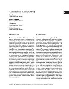
Subsection III-A presents the structural model and its main components. In Subsection III-B, we formally define the data structures to represent loads, configurations, states and functions. Finally, Subsection III-C discusses the computational details of the propagation of the loads and the evaluation of the states for each cloud component. A. Modelling Clouds with C2 LP In C2 LP, the structural arrangement of cloud elements is based in a directed acyclic multigraph (DAM). The nodes of the graph represent components in several abstraction levels, from resources to services. The use of a DAM gives more freedom for the modelling of elements in different abstraction levels, related to a set of fixed layers (i.e. IaaS, PaaS, SaaS). The elements of the model and can be of four types. • Computing, Storage and Networking resources, which are the base of any cloud service. These components are always leaf nodes. • Systems, which are abstractions that orchestrate resources that provide and implement services. They can be, e.g., applications and platforms. In the model, systems must be directly linked to at least one of each type of resource: computing, storage and networking. Nevertheless, these resources might be replaced by other systems or thirdparty services. In such cases, the relationship between the system and the element that represents the resource (i.e., another system or the third-party service) must be explicitly defined using stereotypes (virtual computing, virtual networking or virtual storage). • Third-Party Services, which might represent: (i) resources to system components, when the relation is explicitly annotated with the appropriated stereotype, and (ii) entire systems which provide services and abstract the underlying layers (e.g., email services). The latter models, for example, hybrid clouds or composed services. • Services, which are interfaces between the cloud and the consumers. They are invoked with specification of the consumer’s needs and, in this model, they are converted into loads. Directed edges in our model define to which elements each cloud component can transmit load. Nodes have two main processes: propagation of the load; and evaluation of the impact of the load in the node itself. Remarkably, the resources components do not propagate load and are the only nodes that actually run the assigned load, while other elements are abstract (e.g., applications, middlewares, platforms and
operations systems). Moreover, we consider in the model also the configurations settings of nodes, which impact the propagation and evaluation processes. The cloud offers services and receives requests from consumers. Requests are then propagated to other nodes using a propagation function that defines to which linked node, the division and in which form the load will be propagated. Since loads might have different forms, we model these relations enabling multiple edges between nodes, which simplifies the understanding of the model. For example, a service transmits 10 giga FLoating-point Operations Per Second (FLOPS) and 100 giga bytes of data to third-party service. This relation is modelled using two edges, one for each type of load. In case of change in the structure (e.g., a cheaper storage provider) the model can be adjusted simply by removing the storage edge between these nodes and adding it to this new third-party provider. The evaluation process measures the impact of the load in the resources components and, consequently, on the other nodes of the structure. This process is performed in each node using an evaluation function, which receives three parameters: the configuration of the node, the load defined in the incoming edges and the evaluation of successor nodes. In the case of resource components, the evaluation function uses only the configuration and edge’s loads as input. Figure 1 presents the modelling of a scenario, in which a cloud provides two services: an email and Infrastructure-as-aService (IaaS). The IaaS is provided by a third-party cloud. The email service instead, employs a system component to represent a software email server (in this case a Postfix). This component uses local computing and networking and storage from a third-party cloud. The relation (edge) between these components is annotated accordingly. In the proposed scenario, we exemplify the load propagation with a request from consumers to send 2 new emails using the email service. These 2 emails are converted by the service component into 2 loads of type “transaction” and sent for the email server where, consequently, are converted into another types of load and propagated to the resources linked to the server. The evaluation process of this scenario uses different metrics in each node and is marked as “result:“. For example, in the service level, the load of 2 emails was measured in terms financial cost and energy necessary to complete the request. B. Formalisation of the Model Formally, in C2 LP model, a cloud C can be expressed as C = (V, E, ⌧ V , , , , , , 0 , 0 ), where: • V is the set of nodes V = {v1 , v2 , . . . , vn } of the multigraph, such that every item in V represents one element of the cloud and has one respective node-weight wv , that usually is a vector of values; • E is the set of directed edges where E = {e1 , e2 , . . . , em }|e = (v, v 0 ), that describes the ability of a source node v to transmit a load to node v 0 , such that each em also has a respective edge-weight wv,v0 ; • ⌧ V : V ! T V is a bijective function which maps the nodes with the respective type, where the set T V is the set of types of nodes, such that T V = {0 computing 0 , 0 storage0 , 0 networking 0 , 0 system0 , 0 service0 , 0 third party 0 }; • : E{!system,!third party} ! {none, vComputing,
Figure 1: Example of the propagation of loads and the evaluation processes using the C2 LP model.
vStorage, vN etworking} is a function which maps the edges that have systems and third-party services as target with the respective stereotype, characterising the relation between the source element with the target; • represents the set of propagation functions, where = {f1 , f2 , . . . , fv } and is a bijective function : V ! that maps each node for the respective propagation function. Each function in the set is defined as fv : Nn , Ri ! Ro , where: the set Nn represents the space where the n-tuple for the configuration is contained; the set Ri represents the space where the ntuple of incoming edge-weights is contained; and, Ro is the space where the n-tuple of the outgoing edge-weights is contained. To simplify the model and the algorithms, we consider that configurations are stored in the nodeweight, such that wvconf represents the configuration part of the node-weight vector. • is the set of sets that contains the evaluation functions for the leaf nodes, such that there exists one function for each distinct evaluation metric (e.g., energy use, CO2 emission, . . . ). Then, = { 1 , 2 , . . . k }, such that k = {gn+1 , gn+2 , . . . , gm }. Each set k is related to a leaf node v 2 V[leaf ] through the bijective function : V[leaf ] ! . Every gn+m is stored in a distinct position of the node-weight vector of the respective node – representing a partial state of v – such that the full new state can be computed through the expression: wv0 = (c1 , . . . , cn , gn+1 (c1 , . . . , cn , wvi ), gn+2 (c1 , . . . , cn , wvi ), . . . , gn+m (c1 , . . . , cn , wvi )), where: c1 , . . . , cn is the n-tuple with the configuration part of the node-weight wv ; wvi is the n-tuple with all incoming edge-weights w⇤,v of v; and wv0 is the new node-weight (full state) for v. The complete evaluation procedure is detailed in Figure 3; • 0 is the set of sets that holds the evaluation functions for non-leaf nodes. Therefore, 0 = { 01 , 02 , . . . , 0l },
0 0 0 such that each set 0l = {gn+1 , gn+2 , . . . , gm } con0 tains the evaluation functions gn+m . Every 0l is associated with a non-leaf node v through the bijective function 0 : Vnon leaf ! 0 . Since the result of 0 each function gn+m is stored in a distinct position of wv0 , it represents a partial state of the respective node v. A new full state of non-leaf nodes can be computed through the expression: wv0 = (c1 , . . . , cn , 0 0 gn+1 (c1 , . . . , cn , wvi , wu0 v ), gn+2 (c1 , . . . , cn , wvi , wu0 v ), 0 i 0 . . . , gn+m (c1 , . . . , cn , wv , wuv )); where wv0 is the new node-weight of v, c1 , . . . , cn is the n-tuple with the configuration part wvconf of the node-weight, wvi is the n-tuple with the incoming edge-weights e⇤,v of v, and wu0 v is a tuple which puts together all node-weights of the successors of v (see Figure 3 for details). The main objective of these formalisms is to specify the data structures that support a model validation, the load propagation, and elements evaluations. The details of each procedure concerned with propagation and evaluations are described in Subsection III-C.
C. Details on the Propagation and Evaluation The load propagation consists in a top-down process that uses the breadth-first approach. In a breadth-first algorithm, the loads are propagated to the neighbour nodes before moving to the next level nodes. In the specific case on C2 LP the algorithm starts from the loads on the services, corresponding to the requests received from consumers. The propagation process uses a queue with the service nodes (the roots of the graph). Then, a node v is picked from this queue and all its children are placed into the queue. Afterwards, a function fv = (v) is executed to distribute the load, that is, to define all edge-weights for the outgoing edges of v. This procedure is repeated while the queue is not empty. The well defined method is detailed in Figure 2. When the load is propagated to resources components (leaf nodes), they execute the load. This execution requires power and resources and can be evaluated in several forms. For example, energy (kw), performance, availability, accounting, security, CO2 emissions and other cloud specific feature units. This evaluation process takes every function gn+m 2 k in order and computes each partial states, storing them into a position of the new node-weight wv0 . A finer description can be defined as: wv0 = (wvconf , gn+1 (wvconf , wvi ), . . . , gn+m (wvconf , wvi ), such that wv0 represents the a posteriori state for the node v, wvconf are the configurations (a priori state) of v, wvi are the incoming edge-weights of v, and gn+m 2 (v) are the evaluation functions associated with the node. The evaluations also include the non-leaf nodes since the load also passes through them and it is useful, e.g., to understand the load distribution and to identify bottlenecks. In the case of non-leaf nodes, the evaluation requires also the evaluation results of the bottom nodes. Therefore, this process is performed from the leaves to the roots using a depth-first approach. Resources evaluation occurs according to several models that convert the configuration, loads and the results of other evaluations into node-weights. A non-leaf node receives the tuples (conf ig, loads, children states), and evaluates by the processing 0 0 of all gn+m 2 (v) functions. A representation of this process can be described as: wv0 =
1:
2: 3: 4: 5: 6: 7: 8: 9: 10: 11: 12: 13: 14: 15: 16: 17:
procedure BREADHT F IRST P ROPAGATION(C,W V ,W E ) . Requires a cloud model C = (V, E, ⌧ V , , , ), the set of node-weights W V |8v 2 V ^ 9!wv 2 W V and the set of edge-weights W E |8ev,v0 2 E ^ 9!wv,v0 2 W E. queue ? enqueue(⇤) repeat v dequeue() for each u 2 successorSet(v) do enqueue(u) end for . enqueues the sucessor of each node fv (v) wvconf conf igurationP art(wv ) . gets the config. part of the node-weight (state). wvi (w1,v , w2,v , . . . , wu,v ) . builds the incoming edge-weights in a tuple wvi . wvo fv (wvconf , wvi ) . wvo contains the result of the propagation function. for each wv,u 2 wvo do WE W E wv,u . replaces the old value of wv,u . end for. assign the values for the outgoing edges of v. until queue 6= ? return W E end procedure
Figure 2: Breadth-first algorithm used for the load propagation.
0 0 (wvconf , gn+1 (wvconf , wvi , wu0 v ), . . . , gn+m (wvconf , wvi , wu0 v ), 0 such that wv represents the new node-weight (a posteriori state) for the node v, wvconf are the configuration part (a priori state) of node-weight into v, wvi represent the incoming edge-weights of v, wu0 v are the computed node-weights of 0 the successors of v, and gn+m 2 0 (v) are the evaluation functions associated with the node. The complete evaluation process is detailed in Figure 3, where a stack is used to perform a depth-first computation. The first non-visited child of a current node is placed into the stack and will be used as current node. When all children of a node are evaluated, then the node is evaluated. If the node is a leaf node the g functions are used to compute the evaluations, otherwise, the g 0 functions are used instead. These mathematical structures and algorithms provide a general framework for modelling and evaluation of clouds’ elements behaviour in different abstraction levels. They can express and compute how service level loads are decomposed and converted, through the systems, till become resource level loads. In resource level, on concrete elements, the loads can be evaluated according to performance, availability and other objective metrics. At end, the same structures and algorithms can be used to compute objective metrics for abstract elements. The whole model serves to simulate and compare the impact of configuration’s changes in any point of the cloud, supporting the managerial decision making.
IV. E XPERIMENTS AND R ESULTS This section presents numerical experiments with the C2 LP model, based on a service modelling. These experiments serve to: test the applicability of the model; present a concrete
1: 2: 3: 4: 5: 6: 7: 8: 9: 10: 11: 12: 13: 14: 15: 16:
17: 18:
19:
20: 21: 22: 23: 24: 25: 26: 27:
procedure DEPTH F IRST E VALUATION(C,W V ,W E ) . The same input described in Figure 2. ? . initializes the set of visited nodes. stack ? . initializes the stack. push(⇤) . starts from the hypothetical node. while stack 6= ? do v peek() . gets a node without to remove it. for each u 2 successorSet(v) do if u 2 / then push(u) continue while end if end for . if the for loop ends, all successors have been evaluated. wconf conf igurationP art(wv ) . gets the config. part for v. wvi (w1 , w2 , . . . , wu,v ) . builds the n-tuple with the incomings of v. if isLeaf (v) then wv0 (wvconf , gn+1 (wvconf , wvi ), . . . , conf gn+m (wv , wvi )), 8gn+m 2 (v) . computes the partial states and builds the new node-weight. else wu0 v (wu0 1 , wu0 2 , . . . , wu0 o ) . builds the computed node-weights for all u|9ev,u 2 E. 0 wv0 (wvconf , gn+1 (wvconf , wvi , wu0 v ), . . . , 0 conf i 0 0 gn+m (wv , wv , wuv )), 8gn+m 2 0 (v) . computes the partial states and builds the new node-weight. end if WV W V wv0 . replaces the old state of v into the node-weights. if v 2 / then [v end if . puts v in the visited set if it is not there. v pop() . gets and removes v from the stack. end while return W V end procedure
Figure 3: Depth-first algorithm to evaluate in specific metrics the impact of the load in each node.
example of modelling; and, demonstrate the model capacity for quantitative behaviours generation combining variations of propagation and evaluation functions. To perform these experiments, we have implemented a use case using our model. This use case exemplifies the model’s usage and serves to test its feasibility. The example of model’s usage was made using hypothetical functions, since its objective is to prove the generation of simulations, the propagation and the evaluation. Nevertheless, our model can be used for modelling real-world clouds, provided that the propagation and evaluation functions are adjusted to the cloud instance. As use case, we defined an IaaS service where consumers perform five operation: deploy VM, undeploy VM, start VM, stop VM, and execute tasks. To meet the demand for these
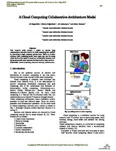
services, we designed a hypothetical cloud infrastructure with which is possible to generate quantitative scenarios of propagation and evaluation – in a combinatorial fashion. Using this hypothetical infrastructure, we have tested some managerial configurations related to load distribution over the cloud elements, in order to evaluate the average utility for all quantitative scenarios. At the end, the configurations which achieve the best average utility for all quantitative scenarios were highlighted, depicting the ability of the model to simulate configuration consequences for the purpose of selecting configurations. A. Use Case Modelling To deal with the consumers’ loads (deploy, undeploy, start, stop and execute) at service abstraction level, the infrastructure manages: the service interface; systems, such as load balancers, cloud managers and cloud platforms; and resources, such as servers, storages and physical networks. All operations invoked by consumers represent an incoming load on the service interface, which is propagated to resources. In the resources the loads are evaluated to provide measures about performance, availability, accounting, security and CO2 emissions. Once computed these measures for resource level elements it is possible to compute they also for systems and, at the end, for the service interfaces, getting service level measures. The modelling of the use case was devised considering 21 components: 1 service, 9 systems, and 11 resources. The services represent the interface with customers. In this use case, the systems are: a load balancer; two cloud manager systems; and six cloud platforms. Also, between the resources there are: 8 physical computing servers (6 work servers and 2 managerial), 2 storages (1 work storage and 1 managerial), and 1 physical network. A detailed list of components is presented in Appendix I. Regarding the edges and loads, each consumer’s operation is modelled as an incoming edge in a service interface node – with the respective loads in the edge-weights. The service node forwards the loads for a load balancer system, where the propagation function decides to which cloud manager the load will be sent, whereas the manager servers, the manager storage and the physical network receive the loads by its operation. In the cloud mangers, the propagation function must decide to which cloud platform the loads will be sent and, at the same time, generate loads for the managerial resources. The cloud platform system effectively converts its loads into simple resource loads when uses the work server, work storage and physical network. The complete relation of load propagation paths is presented in Appendix I, where an element at the left side of an arrow can propagate loads for an element at the right. Furthermore, a graphical representation of these tables, which depicts the graph as a whole, is also presented in Appendix I. Besides the node and the edges, the use case model required the definition of: • 4 types of propagation functions – one for the service and tree for each type of system; • 6 types of leaf evaluation functions – two specific performance evaluations, one for computing resources and another for storage and networking; plus, four common evaluation functions (availability, accounting, security and CO2 emissions) for each type of resource; • 5 types of non-leaf evaluations functions. We have modelled the possible combinations to distribute the loads {1-deployVM, 2-undeployVM, 3-startVM, 4stopVM, 5-compute} as a partition set problem [19], resulting
TABLE II: S UMMARY OF AVERAGE EVALUATIONS FOR EACH CONFIGURATION . Criteria Code Time Availability Accounting Security Emissions Utility
11221 180.59976 0.9979606 78.69924 0.9979606 82848.31 1.0526400204
Configuration 11231 11232 180.5999 180.60004 0.99795955 0.9979587 78.69926 78.699234 0.99795955 0.9979587 82848.14 82848.51 1.0526410547 1.0526477776
11212 180.59991 0.99795926 78.699265 0.99795926 82848.74 1.0526491889
in 52 distinct possibilities of load propagation. Also, we introduced 2 possible configurations into each evaluation function for leaf nodes. These configurations are related to the choice of constants into the function. For example, the performance of a computing resource depends on its capacity, that can be: a = 50GF LOP s or b = 70GF LOP s. Considering 5 distinct evaluation functions over 11 leaf nodes, we have got (25 )11 = 255 possible distinct configurations to test. B. Evaluations The numerical experiments were performed running the propagation procedure, followed by the evaluation of every simulation. For each possible propagation, we tested and summarized the 255 configurations for evaluation functions. Then, we analysed the average time (p, in seconds), average availability (av, in %), average accounting (ac, in currency units), average security (s, in % of risk of data exposition), and average of CO2 emissions (c, in grammes). Each value was normalised according to the average for all propagations, tested and summarised in a global utility function, described in (1) – where the overlined variables represent the normalised values. Such results enable cloud managers to choose the best scenario according to the priorities of the policy or to provide input for the decision-making process, such as Markov Chains. u=
(av + s
(p + ac + c))
(1)
The best four results of the fifty two numerical experiments are presented in Table II in ascending order, where the configuration that achieves the best average utility is highlighted in bold. The code line in the table represents the propagation configuration, whereas the other lines contain the values obtained for each distinct evaluation type. The last row presents the average utility defined in Equation 1. To represent configuration we have adopted a set partition notation to express the propagation paths, such that each position in the code represents a type of load: 1-deploy, 2-undeploy, 3start, 4-stop, and 5-compute. Considering that at leaves of the propagation graph there are 6 cloud platforms, a code 11212 indicates that the loads of type 1,2 and 4 were allocated on cloud platform 1, whereas the loads 3 and 5 ware allocated in the cloud platform 2. V. C ONCLUSION Several solutions have been proposed to model clouds. However, to the best of our knowledge, none is general and has mathematical formalism at the same time, which are essential characteristics for evaluation of decision making and autonomic management. In this study, we have presented an approach with these characteristics to model clouds based in Directed Acyclic
Multigraph, which has the flexibility of general models and the formalism of the specifics. Therefore, C2 LP is a flexible well-formed modelling tool to express flows of loads through the cloud components. This model supports the specification of elements in distinct abstraction levels, the generation of combinatorial variations in a use case modelling and the evaluation of the consequences of different configuration in the load propagation. We developed a simulation software tool for the modelling of IaaS services and demonstrated the applicability of our approach through a use case. In this use case, we simulated several graph network theoretic analysis, evaluated and compared different configurations and, as a result, supplied the cloud managers with a numeric comparison of cost and benefits of each configuration. These experiments, demonstrated that this tools provides an essential support for the management of cloud. ACKNOWLEDGEMENT The present work was done with the support of CNPq agency, through the program Ciˆencia sem Fronteiras (CsF), and the company Eletrosul Centrais El´etricas S.A. – in Brazil. The authors also would like to thank professor Rocco De Nicola and the group of SysMA research unit in Institute for advanced studies Lucca (IMT). R EFERENCES [1] Itzhak Gilboa, “Theory of Decision under Uncertainty,” Cambridge University Press, 2009. [2] Cliff Ragsdale, “Modeling & Decision Analysis,” Thomson, 2008. [3] R. Buyya, R. N. Calheiros, and X. Li, “Autonomic cloud computing: Open challenges and architectural elements,” In Emerging Applications of Information Technology (EAIT), 2012 Third International Conference on. IEEE, 2012, pp. 3–10. [4] Rafael Mendes et al., “Decision-theoretic planning for cloud computing,” In ICN 2014, The Thirteenth International Conference on Networks, Iaria, vol. 7, no. 3 & 4, 2014, pages 191–197. [5] Alexandre A. Flores, Rafael de S. Mendes, Gabriel B. Br¨ascher, Carlos B. Westphall, and Maria E. Villareal, “Decision-theoretic model to support autonomic cloud computing,” In ICN 2015, The Fourteenth International Conference on Networks, Iaria, vol. 8, no. 1 & 2, 2015, pages 218–223. [6] Rafael Brundo Uriarte, “Supporting Autonomic Management of Clouds: Service-Level-Agreement, Cloud Monitoring and Similarity Learning,” PhD thesis, IMT Lucca, 2015. [7] Rafael Brundo Uriarte, Francesco Tiezzi, and Rocco De Nicola, “SLAC: A formal service-level-agreement language for cloud computing,” In Proceedings of the 2014 IEEE/ACM 7th International Conference on Utility and Cloud Computing, IEEE Computer Society, 2014, pages 419–426. [8] Jordi Vilaplana, Francesc Solsona, and Ivan Teixid´o, “A performance model for scalable cloud computing,” In 13th Australasian Symposium on Parallel and Distributed Computing (AusPDC 2015), ACS, vol. 163, 2015, pages 51–60. [9] Paulo F Silva, Carlos B Westphall, and Carla M Westphall, “Model for cloud computing risk analysis,” ICN 2015, Iaria, vol. 8, no. 1 & 2, 2015, page 152. [10]
Nada Ahmed and Ajith Abraham, “Modeling cloud computing risk assessment using machine learning,” In Afro-European Conference for Industrial Advancement, Springer, 2015, pages 315–325.
[11]
Sergio Nesmachnow, Santiago Iturriaga, and Bernabe Dorronsoro, “Efficient heuristics for profit optimization of virtual cloud brokers,” Computational Intelligence Magazine, IEEE, vol. 10, no. 1, 2015, pages 33–43.
[12]
[13]
[14]
[15]
[16] [17]
[18]
[19]
Tim P¨uschel, Guido Schryen, Diana Hristova, and Dirk Neumann, “Revenue management for cloud computing providers: Decision models for service admission control under non-probabilistic uncertainty,” European Journal of Operational Research, Elsevier, vol. 244, no. 2, 2015, pages 637–647. Chunling Cheng, Jun Li, and Ying Wang, “An energy-saving task scheduling strategy based on vacation queuing theory in cloud computing,” Tsinghua Science and Technology, IEEE, vol. 20, no. 1, 2015, pages 28–39. Rodrigo N. Calheiros, Rajiv Ranjan, Anton Beloglazov, Csar A. F. De Rose, and Rajkumar Buyya, “Cloudsim: a toolkit for modeling and simulation of cloud computing environments and evaluation of resource provisioning algorithms,” Software: Practice and Experience, Wiley Online Library, vol. 41, no. 1, 2011, pages 23–50. Dzmitry Kliazovich, Pascal Bouvry, and Samee Ullah Khan, “GreenCloud: a packet-level simulator of energy-aware cloud computing data centers,” The Journal of Supercomputing, Springer, 2012, page 1263– 1283. Alberto N´un˜ ez et al., “iCanCloud: A flexible and scalable cloud infrastructure simulator,” Journal of Grid Computing, Springer, vol. 10, no. 1, 2012, pages 185–209. Rodrigo N Calheiros, Marco AS Netto, C´esar AF De Rose, and Rajkumar Buyya, “EMUSIM: an integrated emulation and simulation environment for modeling, evaluation, and validation of performance of cloud computing applications,” Software: Practice and Experience, Wiley Online Library, vol. 43, no. 5, 2013, pages 595–612. Seung-Hwan Lim, Bikash Sharma, Gunwoo Nam, Eun Kyoung Kim, and Chita R Das, “MDCSim: A multi-tier data center simulation, platform,” In Cluster Computing and Workshops, 2009. CLUSTER’09. IEEE International Conference on, IEEE, 2009, pages 1–9. Toufik Mansour, “Combinatorics of Set Partitions,” CRC Press, 2012.
A PPENDIX I: I MPLEMENTATION D ETAILS TABLE III: T HE CLOUD ELEMENTS – NODES OF THE GRAPH. CS - computing service LB - load balancer CM1 - cloud manager 1 CM2 - cloud manager 2 CP11 - platform 11 CP12 - platform 12 CP13 - platform 13
CP21 - platform 21 CP22 - platform 22 CP23 - platform 23 MS1 - manager server 1 MS2 - manager server 2 MSTO - manager storage WS11 - work server 11
WS12 - work server 12 WS13 - work server 13 WS21 - work server 21 WS22 - work server 22 WS23 - work server 23 WSTO - work storage PN - physical network
TABLE IV: T HE LOAD PROPAGATION RELATIONS – EDGES OF THE GRAPH. 5
5
!CS 5
CP11 ! WS11
CP21 ! PN
5
CP11!WSTO
CP22!W22
CP12!WS12 CP12 ! PN CP12 ! WSTO
CP22 ! PN CP22 ! WSTO CP23 ! W23
5
CP13! PN
5
CP13 ! WSTO CP21 ! W21
CP23 ! WSTO
5
CS !LB
CM1 !CP12
5
LB !CM1
CM1 !CP13
5
LB !CM2 LB ! MS1 LB ! MS2
LB ! WSTO LB ! PN
CM1 !CP11
CM1 ! MS1 CM1 ! MSTO
CM1 ! PN CM2 ! MS2 CM2 ! MSTO 5
CM2 ! CP21 CM2 ! CP22 CM2 ! CP23 CM2 ! PN
CP11!PN
CP13! W13
CP21!WSTO
CP23 ! PN
Computing Service Load Balancer
Cloud Manager 1
Manager Storage
Manager Server 1
Platform 11
Platform 12
Platform 13
Cloud Manager 2 Manager Server 2
Platform 23
Platform 22
Platform 21
Work Server 23
Work Server 22
Work Server 21
Work Storage Work Server 11
Work Server 12
Work Server 13 Phisical Network
Figure 4: Graphical representation of structural arrangement for the modelling use case.
TABLE V: P ROPAGATION FUNCTIONS. Types
Declarations
service
(w1 , · · · , w5 ) 7
Definitions
balancer
(c1 , . . . , c5 , w1 , · · · , w5 ) 7 0 (w10 , . . . , w14 )
f CS
! (w10 , · · · , w50 ) . f LB
!.
n
wn is the weight for ! CS). n 0 wn is the weight for (CS ! LB). 0 0 wn = wn |8wn 2 f CS . cn 2 {CM 1, CM 2}, are the configurations which represent the targets of each load wn |1 6 n 6 5. ⇢ wn if cn = CM 1 0 wn = 16n65 0 otherwise .
0
wn+5 =
⇢
wn 0
if cn = CM 2 otherwise
16n65
. 5 0 w1>n>5 , are the weights in the edges LB !CM1. 5
0 w6>n>10 , are the weights in the edges LB !CM2. 0 w11 = 1Gf lop, is the a constant computing load in LB!MS1. 0 w12 = 1Gf lop, is the a constant computing load in LB!MS2. 0 w13 = 50GB, is the a constant storage load in LB!MSTO. 0 w14 = w1 + 40, is the load over LB!PN, such that w1 is the VM image size in GB, comes from deploy VM operation, and 40 is a constant value in GB for the another operations.
cloud manager
(c1 , . . . , c5 , w1 , · · · , w5 ) 7 0 (w10 , . . . , w18 )
f CM n
!
cn 2 {CP m1, CP m2, CP m3}, are the configurations which represent the targets of each load wn |1 6 n 6 5. ⇢ wn if cn = CP m1 0 wn = 16n65 0 otherwise .
0
wn+5 = . 0
wn+10 =
⇢
wn 0
if cn = CP m2 otherwise
16n65
⇢
wn 0
if cn = CP m3 otherwise
16n65
. 0 w16 = 1Gf lop, is the a constant computing load in CMn!MSn. 0 w17 = 50GB, is the a constant storage load in CMn!MSTO. 0 w18 = w1 + 40, is the load over CMn!PN, such that w1 is the VM image size in GB, comes from deploy VM operation, and 40 is a constant value in GB for the another operations. cloud platform
(w1 , · · · , w5 ) 7
f CP nn
! (w10 , w20 , w30 ).
w1 , · · · , w5 , are the main loads come from the service, associatively, w1 – deploy VM, w2 – undeploy VM, w3 – start VM, w4 – stop VM, and w5 – compute tasks. w10 , w20 and w30 are, respectively, the edge-weight for the arcs CPnn!WSnn, CPnn!WSTO and CPnn!PN, where: w10 = w1 w2 + w3 w4 + w5 ; w20 = w1 w2 + 1M B; w30 = w1 + w3 w4 + 1M B.
TABLE VI: E VALUATION FUNCTIONS FOR LEAF NODES. Types computing specific functions
Functions load performance (duration): d(load) = capacity , where load is expressed in GFlop, capacity is a constant of 70GFLOPs and d is the total time to resolve the load. energy increment (kWh): energyincrement (load) here is considered a linear function which returns the amount of energy necessary to process the load above the average consumption of standby state. For computing have been considered 0.001kW per GFLOP.
storage and network specific functions
load performance (duration): d(load) = capacity , where load is expressed in GByte, capacity is a constant of 1GBps and d is the total time to resolve the load. For the networking resources this concept is intuitively associated with the network throughput, however, for storage is necessary to explain that the performance refers to throughput of the data bus.
energy increment (kW): energyincrement (load) for data transmission is assumed as linear, and was here considered 0.001kW per GB transferred. common functions
availability: av(load) = 1 pf ault (d(load)), where pf ault is the probability which a fault occurs during the load processing. Here will be considered a linear naive probability, such that pf ault (d) = d ⇥ 0.01. accounting: ac(load) = priceenergy ⇥ energytotal , where priceenergy is a constant of 0.38U S$/kW or 0.58U S$/kW , depending on node configuration; and energytotal = energyincrement (load) + energyaverage (d(load)), such that energyaverage (d(load)) = d(load) ⇥ 0.1kW is the shared energy spent by the cloud by time slot, and energyincrement (load) is the increment of energy result of resource usage. security (risk of data exposition): s(load) = 1 pexposure (load), where pexposure (load) is the probability that the load processing results in data exposure and s(load) is the trustability of the operation. The pexposure (load) is calculated as 0.001 for each second of operation. CO2 emission: c = energytotal ⇥ 400, where energytotal was defined in the accounting evaluation function and 400 is a constant which represents the grammes of CO2 per kW .
TABLE VII: E VALUATION FUNCTIONS FOR NON - LEAF NODES. Types performance
Declarations maximum duration of loads sent for successor nodes.
Definitions 0 0 pv (w1 , . . . , w5 , w10 , . . . , wn ) = max(w10 [p], . . . , wn [p]), where pv 0 represents the total time to process the incoming loads, and wn [p] represents the specific part of in the node-weight of n successor nodes, regards to the duration to process the loads sent by the node v.
availability
the product of the availability of successor nodes according to the sent loads.
accounting
the sum of costs relative to the sent loads for successor nodes.
P 0 0 acv (w1 , . . . , w5 , w10 , . . . , wn )= wn [ac], where acv is the total cost 0 related to v and regards to the loads processed in the successors, and wn [ac] is the accounting part of the successors’ node-weight.
security
the product of security (regards to data exposition) of successor nodes according to the sent loads.
Q 0 0 sv (w1 , . . . , w5 , w10 , . . . , wn ) = wn [s], where sv represents the total 0 security measure of a node v, and wn [s] represents the security measure part in node-weights of the successors of v, related to the loads sent.
CO2 emission
the sum of total emissions relative to the loads sent to the successor nodes.
P 0 0 cv (w1 , . . . , w5 , w10 , . . . , wn ) = wn [ac], where cv is the total CO2 0 emission associated with a node v, and wn [ac] is the node-weight part associated with the emissions caused by the loads sent from v.
Q 0 0 avv (w1 , . . . , w5 , w10 , . . . , wn ) = wn [av], where avv represents the 0 total availability of a node v according its dependencies, and wn [av] represents the availability part in node-weights of the successors of v, related to the loads sent.