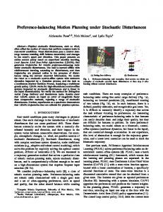
Figure S1. Retinotopic mapping in V1, V2 and V4. (A) Cortical responses to 0.2° wide, 30° long vertical bars presented monocularly. The approximate locations ...
Neuron, Volume 78 Supplemental Information
A Motion Direction Preference Map in Monkey V4 Peichao Li, Shude Zhu, Ming Chen, Chao Han, Haoran Xu, Jiaming Hu, Yang Fang, and Haidong D. Lu
Figure S1. Retinotopic mapping in V1, V2 and V4 (A) Cortical responses to 0.2° wide, 30° long vertical bars presented monocularly. The approximate locations of the bars are labeled below each map. The first map shows V1 V2 activation (yellow arrow) around V1/V2 border, indicating that the position of the bar is at the vertical meridian (0°). The shift of responses in V4 (red arrows) and V1 V2 (yellow arrows) are consistent with previous findings (e.g. Gattass et al., 1988). (B) Similar to (A), cortical responses to horizontal bars. The large V1/V2 activation at about 1° indicates a high cortical magnification at fovea region (c.f. Lu et al., 2009). (C) An illustration of the stimulus locations in the lower right visual field, star indicates the center of the visual field (fovea). (D, E) Re-plot of the approximate centers of V4 activation on the imaged V4 region (D) and a flattened V4 region (E). Scale bar in (B) and (D), 5 mm.
Figure S2. Comparison of subtraction maps and t-test maps. Subtraction maps (top row) and their corresponding t-maps (bottom row) were obtained from the same data sets and were processed with the same filtering and clipping procedures. The first three columns are from case 1 (first column: orientation preference map; second column: color preference map; third column: direction preference map). The fourth and fifth columns are direction preference maps from case 2 and 3, respectively. Domains in corresponding subtraction maps and t-maps are generally the same. The major differences are mostly in the blood vessel regions. Specifically, due to high optical noise in blood vessel regions, subtraction maps display very bright or dark blood vessels. However, since these regions also have large signal variations, they have low t-values in t-maps and thus appear gray. Scale bars in subtraction direction preference maps: 2 mm.
Figure S3. Response time courses of V4 direction-preferring domains. Four direction-preferring domains (1-4 in two maps on the left) are selected for response time course examination. Their optical responses to gratings drifting in 8 different directions were shown on the right. Values represent percentage changes (dR/R) of optical signal with respect to the first two frames, which are blank controls. Note that a negative reflectance change indicates signal. Pixel values within one domain were averaged. The preferred direction shown in the title of each panel is based on the domain color (black or white) in the corresponding direction preference map (on the left). For example, site 1 is 225 -preferring, as it appears white in the 45 vs. 225 map. Time courses of these four regions show that all sites exhibited some response to each stimulus. The directional preference emerges around 0.5-1 seconds after the stimulus onset and is maintained throughout the session. Each polar plot above the curves is averaged from neighboring 4 frames. Overall, the direction selectivity revealed by the time course closely correlates with that revealed by the maps. Each data point is an average of 43 trials, error bars represent SEM.
Figure S4. Direction preference map in V4 are not due to chromatic artifacts or binocular disparity. (A) Direction preference maps and orientation preference maps obtained with 3 different color filter conditions. Narrow-band (bandwidth 20-30 nm) filters were placed in front of the monkey’s eyes: left column, no filter; middle column, 546 nm (green) filter; right column, 630 nm (red) filter. Since color is the same for two comparing conditions, the color activation is subtracted out and does not appear in the resulting maps. Therefore map patterns in direction preference maps (top row) and orientation preference maps (bottom row) do not change with the color in the stimuli. A direction preference map obtained with narrow band color also rules out the possibility that chromatic aberration contributes to the formation of direction preference maps. (B) Direction preference map from Case 2 (same as the top right map in Figure 3) imaged with regular full screen binocular grating stimulus (left) and with monocularly viewing a 4 square grating patch (right). Similar direction preference maps in V4 were obtained, suggesting imaged domains are not due to binocular disparity cues. Lack of response in V2 in monocular condition may due to the smaller stimulus size in this condition. Scale bars: 2 mm.
Figure S5. Single-unit recordings from a direction-preferring domain (Penetration 1 in Figure 6). (A) Direction tuning plots of 6 neurons recorded in a direction-preferring domain (the same neurons shown in Figure 5C penetration 1). (B) Raster plots of the neurons’ responses to 8 different directions. (C) Spike waveforms of the 6 neurons (blue curves) and examples of raw spike train data (selected from the same position of each neuron’s recording). (D) Inter-spike-interval (ISI) distributions for each neuron, calculated from the neuron’s direction recordings (about 100 seconds). Note the presence of notches at 0-3 ms ISI for all the recordings, which indicate that no two spikes fired faster than a 3-ms ISI. The inset for each histogram shows close-up view of the same distribution for 0-10 ms ISI.
Figure S6 Orthogonal relationship between preferred orientation and direction angles. (A) Direction polar map for a selected V4 region in Case 1. The insert is a direction preference map (same as Figure 1G) showing the region of selection (red frame). (B) Orientation polar map for the same region as shown in A. The insert shows the orientation difference map (same as Figure 1E) and the region of selection. (C) Orientation-direction angle map from two polar maps showing the orientation preference (short bars) and direction preference (arrows) at each location. The lengths of the arrows/bars are proportional to the strength of the direction/orientation preference. Background colors are from Figure 6D (shows in the insert), in which orange color represents orientation-preferring domains, green color represents direction-preferring domains, and yellow color represents overlapping regions between orientation and direction. For regions having both orientation and direction preferences (yellow regions), the preferred direction are mostly orthogonal to the preferred orientation. (D) Distribution of the angular differences between preferred direction and preferred orientation for all V4 regions having both orientation and direction preference. The relationship tends to be orthogonal (90-degree).