A multithreaded PowerPC processor for commercial servers
by J. M. Borkenhagen R. J. Eickemeyer R. N. Kalla S. R. Kunkel
This paper describes the microarchitecture of the RS64 IV, a multithreaded PowerPC® processor, and its memory system. Because this processor is used only in IBM iSeriesTM and pSeriesTM commercial servers, it is optimized solely for commercial server workloads. Increasing miss rates because of trends in commercial server applications and increasing latency of cache misses because of rapidly increasing clock frequency are having a compounding effect on the portion of execution time that is wasted on cache misses. As a result, several optimizations are included in the processor design to address this problem. The most significant of these is the use of coarse-grained multithreading to enable the processor to perform useful instructions during cache misses. This provides a significant throughput increase while adding less than 5% to the chip area and having very little impact on cycle time. When compared with other performanceimprovement techniques, multithreading yields an excellent ratio of performance gain to
implementation cost. Second, the miss rate of the L2 cache is reduced by making it four-way associative. Third, the latency of cache-tocache movement of data is minimized. Fourth, the size of the L1 caches is relatively large. In addition to addressing cache misses, pipeline “holes” caused by branches are minimized with large instruction buffers, large L1 I-cache fetch bandwidth, and optimized resolution of the branch direction. In part, the branches are resolved quickly because of the short but efficient pipeline. To minimize pipeline holes due to data dependencies, the L1 D-cache access is optimized to yield a one-cycle loadto-use penalty.
1. Introduction This paper describes the microarchitecture of a multithreaded PowerPC* processor and its memory system that has been optimized for server workloads. Codenamed SStar, this processor is known externally as the RS64 IV in the pSeries* 6000 (previously RS/6000*). It became available for purchase in the fourth quarter of
娀Copyright 2000 by International Business Machines Corporation. Copying in printed form for private use is permitted without payment of royalty provided that (1) each reproduction is done without alteration and (2) the Journal reference and IBM copyright notice are included on the first page. The title and abstract, but no other portions, of this paper may be copied or distributed royalty free without further permission by computer-based and other information-service systems. Permission to republish any other portion of this paper must be obtained from the Editor. 0018-8646/00/$5.00 © 2000 IBM
IBM J. RES. DEVELOP.
VOL. 44 NO. 6 NOVEMBER 2000
J. M. BORKENHAGEN ET AL.
885
886
2000. This paper describes SStar, which is the fourth version of the family of processors (Northstar, Pulsar, and IStar) which first began shipping in the iSeries* 400 (previously AS/400*) servers in 1998. Because these processors are used only in iSeries and pSeries commercial servers and are not used in any workstations, they have been optimized solely for commercial server workloads. In particular, little emphasis was placed on SPECfp [1]. As a result, the microarchitecture of these processors is somewhat different from that of other processors. The server workloads used represent such market segments as on-line transaction processing (OLTP), business intelligence, enterprise resource planning (ERP), web serving, and collaborative groupware. The applications are often large and function-rich; they use a large number of operating system services and access large databases. These characteristics make the instruction and data working sets large. These workloads are also inherently multiuser and multitasking. The large working set and high frequency of task switches cause the cache-miss rates to be high [2– 4]. In addition, these references point out that such applications can also have data that is frequently read–write shared. In multiprocessors, this can make the miss rates significantly higher. Also, because of the large instruction working set, branch-prediction rates can be poor. These characteristics are all detrimental to the performance of the processor. Current trends in application characteristics and languages are likely to make this worse. Object-oriented programming with languages such as C⫹⫹ and Java** has been popular for several years and is increasing in popularity. Virtual-function pointers are a feature of these languages that did not exist in the languages used in older applications. Virtual-function pointers lead to branches that can have very poor branch-miss prediction rates. The frequency of dynamic memory allocation in these languages is also higher than in older languages, which leads to more allocation of memory from the heap. Memory from the heap is more scattered than memory from the stack, which can cause higher cache-miss rates. Java also does “garbage collection.” Garbage collection has access patterns that lead to poor cache-miss rates because it references many objects and uses each only a small number of times. All of these factors are causing the already high miss rates of server workloads to become even higher. A large portion of the execution time can already be spent on cache misses and branch mispredictions. The trend in processor microarchitecture is toward decreasing cycle time at a faster rate than the decrease in memory access time. This is causing the number of processor cycles for a cache-miss latency to increase. For a given miss rate, this causes the portion of the execution time due to cache misses to become larger. This trend, combined with the
J. M. BORKENHAGEN ET AL.
trend toward higher miss rates in workloads that already have high miss rates, causes a compounding effect on the cycles-per-instruction (CPI) increase due to cache misses.
2. Multithreading In a multithreaded processor, the processor holds the state of several tasks/threads. The several threads provide additional instruction-level parallelism, enabling the processor to better utilize all of its resources. When one of the threads would normally be stalled, instructions from the other threads can utilize the processor’s resources. The observation that cache misses were becoming a very large portion of the execution time led to the investigation of multithreaded hardware as a way to execute useful instructions during cache misses. Multithreading has previously been shown to increase throughput in the presence of pipeline dependencies and cache misses [5–7]. While multithreading is not a new idea, it had not previously been used in mainstream processors. Moreover, it had not been used in processors targeted at commercial server applications. Because this is the most unique feature of the processor and because the orientation toward commercial server applications has led to a unique approach, this section describes the motivation and rationale for the philosophy and implementation of multithreading in this processor. An important aspect of commercial servers is the ability to run previously compiled applications without changes. To minimize the impact on software, a decision was made that the multiple threads would appear like multiple processors. As a result, only that small part of the operating system dealing with task dispatching and interrupts had to be modified. The multiuser, multitasking nature of commercial server workloads provides an abundance of natural thread-level parallelism, which keeps the multiple threads in the hardware occupied without requiring applications or the operating system to be further parallelized. Because all commercial servers are already multiprocessors, making the multiple threads per processor look like multiple processors to the software did not require any change in the applications and required very little change in the operating system. Of course, a single task could be parallelized into multiple threads to increase the performance of that single task. Another issue that affects software is performance scalability on a multiprocessor system. It is more difficult for software to scale well on a large number of “processors.” To minimize potential application scalability problems, the number of threads per processor is kept small. In commercial servers, system throughput is the primary measure of performance, but single-task execution speed must also be competitive. Several decisions were made to ensure that the performance of a single task would be
IBM J. RES. DEVELOP.
VOL. 44 NO. 6 NOVEMBER 2000
acceptable. Most significantly, the area on the chip devoted to multithreading had to be small, and the cycletime impact had to be very small. To keep the area impact small, only two threads are implemented. While there is more throughput from more threads, performance analysis showed that two threads achieve most of the performance gain and that the performance benefit from each additional thread decreases [8]. Also, to keep area small, little more than the architected state of the task is duplicated. That is, the general-purpose (GPR), floatingpoint (FPR), and most special-purpose registers (SPR) are duplicated, but little else. All other major facilities such as the functional units, level-one (L1) and level-two (L2) caches, and TLBs are shared between the two threads. Performance analysis also showed that there is only a small effect on the miss rates of the caches, particularly the L2 cache, which has the longest latency for a miss [9]. When the chip was completed, there was very little impact on cycle time, and less than 5% of the chip area was used to support multithreading. In addition to minimizing the area and cycle-time impact, another important aspect of single-thread performance was that the single task also had to be able to consume all of the resources of the processor when needed. In fine-grained multithreading, a different thread is executed every cycle [7]. So, for example, if there are N threads, each must have access to 1/Nth of the execution cycles of any resource in the processors. Even if N is only 2, there is a large impact on the execution speed of a single task. While fine-grained multithreading covers control and data dependencies quite well (although this may require more than two threads), the impact of cycle interleaving on single-task performance was deemed too large. As a result, the processor is designed to exploit coarse-grained multithreading. In coarse-grained multithreading, a single thread, called the foreground thread, executes until some long-latency event such as a cache miss occurs, causing execution to switch to the background thread. If there are no such events, a single thread can consume all execution cycles. This minimizes the impact on single-task execution speed, making it performance-competitive with non-multithreaded processors. Similar performance characteristics could also be achieved with simultaneous multithreading [10], but because the processor executes instructions in order, coarse-grained multithreading is the natural choice. In an out-of-order processor, simultaneous multithreading would be the natural choice. The use of coarse-grained multithreading enables a single thread to consume all execution cycles, but it does so only if that thread has no events that trigger a thread switch. To give the task (i.e., the program) some degree of control on execution speed, multiple priority levels are implemented. Letting a task set its priority low or high
IBM J. RES. DEVELOP.
VOL. 44 NO. 6 NOVEMBER 2000
allows it to consume either very few of the execution cycles or most of them (by restricting which events trigger a thread switch). Low priority can be used, for example, when a thread has no task to execute and is executing an idle loop. Executing in low priority allows it to consume very few execution cycles and permits the other thread to use most of the execution cycles. Another example of the use of low priority is during spinning on a lock. The effect of multithreading on response time to the user is also a concern, because a task appears to execute more slowly. While the implementation allows a single task to have competitive performance, it does so by allowing the lower-priority thread on the processor to have very few execution cycles, in which case the throughput increase is small. If all tasks use high priority, the purpose of priority is defeated, and nothing is gained. Maintaining good user-level response time cannot be achieved by using priority. First, note that user-level response time in commercial servers is usually dominated by disk access time and network delays, and these are not affected by multithreading. Performance analysis of the processor portion of user-level response time showed that response time actually improves with multithreading for most levels of utilization [9]. Only at very low utilization does response time degrade. At high utilization, for which response time is most critical, response time improved the most. It is true that the execution speed of a task is slower with multithreading. However, with multithreading the number of processors that the operating system “sees” is larger, so it can dispatch tasks sooner. Because the queuing time on the task-dispatcher queue is smaller, total response time is smaller with multithreading. In addition to providing increased throughput, multithreading can also improve cost performance for the mid-range and low end of the product line. If useful work can be done during cache misses, throughput is less sensitive to the frequency of cache misses and less sensitive to the latency of each cache miss. This yields increased throughput for models with small L2 caches that have very high miss rates or long latencies. Or, for a given throughput level, cost can be reduced by using a smaller L2 cache, slower SRAM for the L2 cache, or slower DRAM for main memory. By keeping the chip area devoted to multithreading small, the cost increase for the processor chip was kept small. This kept the chip size comparable to that of a non-multithreaded processor and made it competitive for the cost-sensitive range of the product line. Finally, as mentioned in the Introduction, the trends of increasing cache-miss rates and increasing latency of cache misses as processor frequency increases will cause the throughput benefit of multithreading to increase over time. The throughput benefit of coarse-grained multithreading is largely a function of the portion of the
J. M. BORKENHAGEN ET AL.
887
6XX/L2 DATAFLOW
L1 DCACHE CONTROLLER
TEST INTERFACE AND CONTROL
FIXED POINT UNIT
FLOATING POINT UNIT
L1 INSTRUCTION CACHE
TRANSLATION LOOK-ASIDE BUFFER
INSTRUCTION UNIT
L1 DCACHE CONTROLLER 6XX/L2 DATAFLOW L1 DATA CACHE
● ●
LINE BUFFER CONTROLLER
L2 CACHE CONTROLLER L2 CACHE DIRECTORY
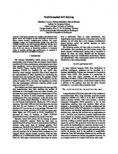
with redesign of timing-critical paths. The L1 I-cache and L1 D-cache were both increased from 64 KB to 128 KB. The L1 I-cache was changed from direct-mapped to twoway associative, and the L2 cache directory was integrated into the processor chip. The processor die, containing 44 million transistors, is shown in Figure 1. It is manufactured in the IBM 1.5-V 0.18-m copper CMOS 8S technology, with seven levels of copper interconnect. The processor has the following attributes:
●
L2 CACHE DIRECTORY
6XXBUS CONTROLLER
●
● ●
PLL ●
Figure 1 Die photo of processor chip.
● ● ● ● ● ●
execution time that is consumed by cache misses. As this portion increases, the throughput benefit increases. The trend toward long pipelines was also noted in the Introduction. Simultaneous multithreading covers control and data dependencies as well as cache misses. As pipeline length increases, so do the penalty for a branch-miss prediction and the number of cycles consumed by the execution of data-dependent instructions. Reducing the impact of these increasing penalties will further improve the throughput benefit of simultaneous multithreading over time. The remainder of the paper is outlined as follows. The next section gives an overview of the chip. Section 4 describes the processor core, and Section 5 the storage control unit. Section 6 presents the multithreading implementation in more detail, and Section 7 gives some performance information.
3. Processor chip overview
888
The SStar processor supports both the 64-bit PowerPC and the PowerPC AS architectures and is the fourth in the family of processors that started with Northstar. The microarchitecture of these processors originated with a previous PowerPC AS processor [11]. The operating frequency of SStar was increased to 600 MHz compared with Northstar’s 262-MHz debut. This increase in frequency was accomplished by leveraging IBM’s CMOS 8S copper and silicon-on-insulator (SOI) technology, along
J. M. BORKENHAGEN ET AL.
Two-way multithreaded. 128KB on-chip L1 I-cache, two-way associative. 128KB on-chip L1 D-cache with one-cycle load-to-use latency, two-way associative. On-chip L2 cache directory that supports up to 16 MB of off-chip L2 cache. 19.2GB/s L2 cache bandwidth. 512-entry translation lookaside buffer (TLB), four-way associative. Branch mispredict penalty of zero or one cycle. Four-way superscalar. Five-stage pipeline. 32-byte-wide on-chip buses. 600-MHz operating frequency. 128-mm 2 die size. 12 W maximum power at 600 MHz.
4. Microprocessor core description Figure 2 shows the high-level dataflow of the major functional units of the processor and memory subsystem. Instruction fetching and branching are controlled by the instruction unit, which fetches up to eight PowerPC instructions from the L1 I-cache each cycle. To efficiently handle instruction-address translation, an effective-to-real address translation cache (IERAT) is incorporated into the instruction unit. The IERAT contains 64 entries for each thread. Each entry maps one 4KB effective address for a page to its corresponding real address in memory. The fetched instructions are placed in one of three buffers: 1. A sequential buffer, which holds up to 16 instructions from the sequential execution path. 2. A branch-target buffer, which holds up to eight instructions from a branch target. This buffer is loaded when a branch is detected in the first six instructions of the sequential buffer. 3. A thread-switch buffer, which holds up to eight instructions from the background thread, so that they may be dispatched immediately after a thread switch without waiting for the latency of the L1 I-cache. The large buffers, high bandwidth to the L1 I-cache, and short pipelines eliminate the need for branch-
IBM J. RES. DEVELOP.
VOL. 44 NO. 6 NOVEMBER 2000
Instruction unit Branch execution unit
Processor chip 128KB L1 instruction cache, 128B line, two-way associative 128-entry IERAT
Sequential buffer 16 instructions
Branch target buffer 8 instructions
32 Byte
Thread switch buffer 8 instructions
Instruction decode and dispatch Execution units FPRs two-way multithreaded
Floatingpoint unit
Loadstore unit
Simple and complex integer unit
Simple integer unit
GPRs two-way multithreaded
16B
Storage control unit
128KB L1 data cache 128B line, two-way associative
L2 cache directory
32 Byte 32B
L2 cache interface unit
Address
512-entry TLB
7 line buffers
16B
6XX bus interface unit
Memory management unit 32B data
L2 cache 0 –16MB 128B line 1– 4-way associative
Command 16B data
Switch
Switch
16B data Command 16B data
Memory controller
DRAM
Switch
Memory controller
DRAM
Figure 2 Processor and memory system.
prediction logic. This is because the processor is able to have both the sequential instruction stream and the branch-taken stream already prefetched into buffers when the branch is resolved. Then, using early branch resolution, the processor simply dispatches instructions from the correct path when the branch is resolved. If an IERAT miss or an L1 I-cache miss occurs during instruction fetching, the processor will switch to the
IBM J. RES. DEVELOP.
VOL. 44 NO. 6 NOVEMBER 2000
background thread. While the new thread is executing instructions, the instruction unit will handle the IERAT or L1 I-cache miss in the background. When the miss is completed, the processor can switch back to the thread that generated the miss and continue executing instructions from that original thread. To further improve performance, a feature was built into the processor to automatically generate an L1 I-cache line fill when an
J. M. BORKENHAGEN ET AL.
889
Cycle
InstrEA
0
1
cmp or sub bc add
2
ld
Instruction stream 100 cmp 104 or Look ahead and find branch, 108 sub target address generation for 10C bc 140 target buffer 110 add ...
3
4
5
6
7
8
140 ld
I-cache data
cmp or sub bc add
Dispatch
Execute/agen
Cache/translate
ld
Target fetch
sub cmp bc or add
Target dispatch when branch resolves
ld
sub cmp bc or add
ld
sub cmp bc or add
Writeback/commit
Cancel sequential instruction (add)
ld
cmp sub or bc
ld
Figure 3 Timing diagram of zero-cycle branch.
IERAT miss occurs. This prevents multiple thread switches from occurring when an IERAT miss also results in an L1 I-cache miss, which is predominantly the case. The instruction unit is the central point of control for multithreading and interrupt processing; it maintains the status of both threads and performs thread switches. The instruction unit contains the control and status registers of each thread, as described in Section 6. This information is used to determine why a thread switch occurs and what event is necessary to return to the original thread. When an interrupt occurs, the instruction unit uses the threadstatus and control registers to determine the thread to which the interrupt is routed. The instruction decode and dispatch stage is responsible for decoding and dispatching up to four PowerPC instructions each cycle. Instructions are dispatched in program order from one of the three instruction buffers. In the same cycle as dispatch, operands are read from architected registers, completion buffers, or result buses. The processor contains five superscalar execution units: ● ● ● ● ●
890
Simple integer point unit (R-pipe). Simple and complex integer unit (M-pipe). Load/store (S-pipe) unit with register moves. Branch execution unit (B-pipe). Floating-point unit (FPU), which uses the M-pipe dispatch.
J. M. BORKENHAGEN ET AL.
During the execute stage, the arithmetic and operand address generation (Agen) functions are performed. Two of the four superscalar units are fixed-point units (FXUs) and have single-cycle execution for the bulk of the integer arithmetic instructions. One of the FXU units is specialized to execute complex, multicycle integer instructions such as multiply and divide. The third unit is a load-store unit which includes a custom dynamic adder to allow for high-speed operand address generation. Condition register lookahead logic based on the arithmetic operations, rotate zero-detect, and a sign bit can bypass into the conditional, branch-taken logic. If any of the input operands are invalid due to dependencies, the execute stage for that pipeline will stall. The fourth unit is the branch execution unit (B-pipe), which is contained inside the instruction unit. The B-pipe processes branch and condition code manipulation instructions. For branch processing, the branch logic looks ahead six instructions into the sequential buffer for branches. The first branch instruction found is decoded, and the branch target address is generated and sent to the instruction cache. By default, branches are predicted as “not taken”; that is, instructions are dispatched and executed down the “not-taken” path prior to the outcome of the branch instruction becoming known (recall that target instructions are placed in the branch target buffer). Once the outcome of the branch instruction is known, and if the branch should have been taken, these previously dispatched instructions are canceled. The branch-taken logic switches dispatch from the sequential instruction buffer to the branch target instruction buffer. Then, up to four instructions are dispatched to the execution units, and any remaining instructions in the branch buffer are moved to the sequential buffer. If the branch direction is known by the end of the dispatch stage, there is no branch penalty. This is known as a “zero-cycle” branch; it is illustrated in Figure 3. In this case, when the branch instruction (bc) is dispatched in cycle 3, the results of the compare (cmp) are also known. Therefore, in cycle 4, the branch target (the ld instruction) is dispatched. A branch penalty is defined as the time from the dispatch of a branch instruction to the dispatch of the target of the branch instruction. Figure 4 shows the case in which an instruction modifies the condition register by being dispatched in the same cycle as a conditional branch. This incurs only a one-cycle branch penalty. Fast switching between the sequential and branch buffers was critical for the processor to obtain its goal of fast branch resolution; this was one of the most highly tuned timing paths in the processor. The compare and the branch are fetched from the L1 I-cache during the same cycle (cycle 1). During cycle 3, the compare is decoded and dispatched while the target address of the branch is fetched. During cycle 4, the compare and branch
IBM J. RES. DEVELOP.
VOL. 44 NO. 6 NOVEMBER 2000
InstrEA
0
1
or sub cmp bc add
2
ld
Instruction stream 100 or 104 sub Look ahead and find branch, 108 cmp target address generation for 10C bc 140 target buffer 110 add ...
3
4
5
6
7
8
Stage 1
Cycle
Stage 2
Read @
From FXU
From SCU
Arithmetic instructions
Aligned data
Read @
Data in
FPRs
Data out
Data out
Data out
Fb
Fa
Fc
Data in
One-cycle delay
Execute/agen
Cache/translate
Writeback/commit
cmp bc add or sub
Target dispatch when branch resolves
ld cmp bc add or sub
Stage 3
or sub
ld cmp bc add or cmp sub bc
ld
Cancel sequential instruction (add) ld
Addend align
Fraction Stage 4
Dispatch
Target fetch ld
Data out
Figure 4
Multiply
Carry
Align Leading zero predict
Sum Add
Intermediate
Stage 5
I-cache data
From FXU
Store data
140 ld or sub cmp bc add
To SCU
Normalize
Timing diagram of one-cycle branch. Stage 6
Unrounded
are executed in parallel. The condition code information from the compare is passed to the instruction-fetch unit in time to direct it to use the target instructions for decode and dispatch on the next cycle. Figure 3 and Figure 4 also illustrate several other characteristics of the instruction-fetch unit of this processor. First, it always speculatively executes down the not-taken path. In these figures, the add instruction sequentially follows the branch in the instruction stream. This instruction is dispatched with the branch and the compare and will execute in the same cycle as the compare. If the branch is taken, as in this example, the add is canceled in the writeback stage before its results are written to the register file. The second characteristic is that the branch target is always fetched unless the branch is already known to be not-taken. These instructions are placed in the branch target buffer described earlier. This enables execution to start down the taken path as soon as it is known that the branch is taken. The last execution unit is the floating-point unit, shown in Figure 5. Floating-point arithmetic instructions are first dispatched to the M-pipe. The M-pipe decode logic will then pass on any floating-point arithmetic instructions to the FPU. In a way similar to that used for floating-point arithmetic instructions, floating-point storage instructions are dispatched to the S-pipe, then passed to the floating-
IBM J. RES. DEVELOP.
VOL. 44 NO. 6 NOVEMBER 2000
Round Result
Figure 5 Floating-point unit.
point unit to provide the necessary FPR facilities. One arithmetic instruction and one storage instruction can be issued to the FPU each cycle. The six-stage FPU has one four-stage multiply–add pipeline. All floating-point arithmetic operations use the facilities in this pipeline, but some operations require more than one pass through it. The floating-point unit is designed to execute one dependent multiply–add instruction every fourth cycle. Nondependent instructions may be processed during the open cycles between dependent operations. This is accomplished by bypassing results from the rounding stage directly to the multiply–add stage. No additional cycles are required when handling denormalized operands or producing denormalized results. The multithreaded FPR file holds two sets of 32 architected registers. In addition to the 64 bits of architected data per register, other flag bits are kept:
J. M. BORKENHAGEN ET AL.
891
● ● ● ●
Implicit bit: The bit to the left of the binary point. Exp1s: The exponent is all 1s. NFrac0s: The fraction is not all 0s. Single: The data fits in single format, possibly held in a denormalized form.
These additional flags are used by the FPU to speed up execution. In order to efficiently use register files to support multithreading, the processor contains two copies of both the GPRs and the FPRs [12]. The register files are designed with a two-memory-element cell. The GPR file supports eight read ports and three write ports. The read ports access only the foreground-thread registers, while the write ports have the capability to update either the foreground-thread or background-thread registers. The eight read ports allow three GPRs to be fetched simultaneously by the M- and S-pipes. The R-pipe (simple-integer) executes only instructions that require two input operands, and therefore uses only two read ports. The M-, S-, and R-pipes all have dedicated write ports. The background write capability is used to support background-thread instruction completion when data is returned for an L1 D-cache miss after a thread switch. The FPR supports four reads and two writes. The four read ports support the three-operand floating-point multiply–add operation, plus an additional read port for floating-point stores. The write ports are used to write floating-point results and data returning from storage for floating-point loads. The physical design of both register files was constrained by wiring density because of the large number of read and write ports. Because the design was wiring-constrained, the additional memory element in each cell to support multithreading did not increase the size of the register files.
5. Storage control unit (SCU) implementation
892
The storage control unit is composed of the L1 D-cache, the L2 cache, the bus interface unit (BIU), and the memory management unit (MMU). The memory management unit consists of control logic that translates addresses, detects cache misses, initiates cache-miss requests, tracks cache-miss responses, and forwards cachemiss data to the processor execution units. The memory management unit also maintains coherency in the L1 and L2 caches. In order to achieve high processor performance with minimal complexity, it is important to keep the cache latencies as small as possible. The processor is microarchitected so that the L1 D-cache access has a onecycle load-to-use penalty. The L1 D-cache is designed to be as large as possible without increasing the load-to-use penalty to two cycles. Data from the L1 D-cache bypasses
J. M. BORKENHAGEN ET AL.
data directly into the execution units. The L1 D-cache is shared between the two threads. The L1 D-cache is built with single-port array components. Single-port arrays are considerably more dense than multiport arrays (which are commonly used for L1 caches). The improved density of single-port arrays can be used to provide more cache entries in the same amount of area, maintain the same number of entries and decrease chip area, or both. Adding cache entries improves the cache-miss rate, which improves performance. Decreasing chip area results in shorter wiring distances to and from the cache arrays, allowing cache-access latencies to be minimized. This processor leverages the single-port array density to both increase cache entries and minimize wiring distances. The L1 D-cache array components are arranged into four independently addressable banks. Each bank has an eightbyte data interface. When an execution unit reads the cache, data from both associativity sets is accessed from the banks, but only data from the predicted set is returned. There is a 16-byte interface to the execution units and a 32-byte interface for cache-line replacement. Cache-miss writes, castout reads, and stores normally done with a second cache port are accomplished on the processor by queuing them in a line-fill buffer and a store buffer. The fills and stores are done either during background cycles, when the execution units are not accessing the L1 D-cache, or simultaneously with instructions that operate on eight bytes of data or less. The majority of instructions operate on eight bytes of data or less, and these instructions use at most two L1 D-cache banks, which is one half of the available L1 D-cache interface. The line-fill buffer holds seven cache lines, and any portion of a line can be stored to or read from. A high-speed bypass path around the line buffer exists for the first data transfer coming from the L2 cache or main store and going directly to the execution units. Storage accesses are executed in order for each thread. Hardware supports a maximum of three outstanding cache misses combined between the two threads. A maximum of two L1 cache misses for each thread is supported by the hardware: one L1 D-cache miss and one L1 I-cache miss. Address-compare logic detects the condition in which both threads simultaneously encounter a cache miss to the same address. Only a single outstanding cache-miss request is allowed to the BIU for a given address. A cache-miss request is sent to the BIU for the thread that first encountered its cache miss, and the cache miss for the other thread is blocked from going to the BIU. After the cache-miss data is returned for the first thread, the second thread re-accesses the address and usually gets a cache hit. When cache data returns for a thread that is not currently executing, the cache-miss data is written into
IBM J. RES. DEVELOP.
VOL. 44 NO. 6 NOVEMBER 2000
the GPR in the background during a cycle in which the opposite thread is not using all GPR write ports. Most of the MMU logic is shared between threads. When both threads are waiting to use the same logic, the foreground thread is normally given higher priority than the background thread. The MMU logic is designed with time-out counters and cache-miss retry counters with programmable thresholds. When one of the counters reaches its threshold, it causes the control logic to alter the priority of the threads. This approach allows thread priorities in the control logic to be set to provide optimal performance while still preventing deadlock and livelock situations introduced by supporting more than one thread. The on-chip BIU contains the L2 cache directory, interface logic to support up to a 16MB L2 cache, and a 6XX system bus interface. The on-chip L2 cache directory contains an entry for each 128-byte cache line held in the 16MB L2 data cache. A thread bit was added to the 6XX bus transaction tag ID. The thread bit is returned on the bus with cache-miss data. Various techniques were used to minimize the L1 D-cache miss penalty to eight cycles. The L2 SRAM clocking logic is designed to tolerate a wide range in access delays caused by SRAM process variation without adding latency to the access path by using a source-synchronous interface combined with a barrel shifter. The L2 cache is implemented with SRAMs external to the processor chip. The external L2 cache is four-way set associative. Associativity in the L2 results in significantly lower L2 cache-miss rates for commercial server workloads. In a four-way associative cache, all four directory entries and all four data blocks are usually accessed in parallel, and then the proper data block is selected after the address and tag are compared. With an external L2 cache, this would require too many pins to fetch all four data blocks. Instead, a history-based prediction array was added to the processor that predicted which of the four blocks would be needed, and only that block was accessed in parallel with the directory access. If the prediction was incorrect, the correct block was then accessed. Note that this added latency penalty was incurred only if the prediction was incorrect AND there was a hit in the L2 cache. There is no added latency for an L2 cache miss. A new generation of SRAM technology was required to support the L2 data-cache bandwidth requirements of the processor. The new double-data-rate (DDR) SRAM technology provides two transfers of data on the 32-bytewide L2 data bus every SRAM clock cycle. The L2 SRAM clock cycle time is 300 MHz, resulting in an L2 data-cache bandwidth of 19.2 gigabytes per second (GB/s). The new SRAM technology also provides low-latency data accesses, resulting in an L1 D-cache miss penalty of eight 600-MHz processor cycles.
IBM J. RES. DEVELOP.
VOL. 44 NO. 6 NOVEMBER 2000
Instructions that affect multiprocessor scalability, such as those related to locks, TLB, cache management, and synchronizing, are optimized for performance in the storage control unit microarchitecture. For multiprocessor storage synchronization, each thread has its own reservation register for use in load-reserved and storeconditional instructions. While the threads share data in L1 and L2 caches, the reservations are distinct in the same way that two independent processors could share caches while having separate reservation registers. Each reservation monitors the activity of the other thread in the same processor just as it monitors the activity of other processors. Reservation information is bypassed between pipeline stages to prevent pipeline stalls. The TLB table-walk routine is implemented in circuits instead of microinstructions to reduce TLB miss latency. If a thread encounters a cache miss during the TLB table-walk routine, a thread switch occurs, and the cache-miss data for the table walk is retrieved in the background. The cache-coherency scheme as implemented does not require synchronizing instructions to be broadcast on the 6XX system bus, minimizing the performance impact caused by synchronization. Synchronization logic was implemented on a per-thread basis in the MMU, preventing a thread from having to wait for synchronization because of an operation on the opposite thread. ● System implementation A key challenge to the BIU was to design the highbandwidth system interface required to support the high miss rates driven by commercial server workloads. Advanced packaging technology was used to implement separate, independent 16-byte main store and 32-byte L2 buses, each with separate address, data, and control lines. The L2 interface achieves up to 19.2-GB/s data transfer rates at 600 MHz. The chip has a total of 2030 chip I/Os, of which 985 are signal I/Os. The BIU is designed to allow flexibility in system implementation from low-cost, bus-based systems to more complex switch-based configurations providing greater address and data bandwidth. An example of a switchbased configuration is shown in Figure 2. The processor design supports the modified-exclusive-shared-invalid (MESI) snooping cache coherence for increased throughput and large system topologies. One characteristic of OLTP workloads is a high rate of read–write data sharing between processors. The SCU provides improved performance in this environment by allowing cache lines to be transferred directly between processors with a technique called intervention. This results in a shorter cache-miss latency than the latency to retrieve L2 cache-miss data from main store. Some recent server main-storage systems do not have this characteristic [4, 13].
J. M. BORKENHAGEN ET AL.
893
6. Multithreading implementation
894
In order to operate two threads within a single processor, the architectural state of each thread must be maintained in the hardware. The state of a thread consists of the GPRs, FPRs, condition register (CR), count register (CTR), link register (LR), fixed-point exception register (XER), and floating-point status and control register (FPSCR) as described in the PowerPC architecture [14]. In addition, there are a number of privileged-mode special-purpose registers (SPRs) that are also part of the state, such as the machine state register (MSR) and machine status save/restore registers 0 and 1 (SRR0 and SRR1). All of the registers specifically listed above are replicated for each thread in order to establish a complete and private state set. None of the replicated facilities are very large; in fact, the largest parts of the design, such as the caches and TLBs, are all shared by both threads. As described in Section 4, the physical implementation of some of these registers is unique to multithreaded designs. While some SPRs must be replicated, a number of other SPRs are shared by the threads. For example, the registers used to configure the system (for example, specifying the address of the hashed page table) are shared. In addition, a number of control registers (described below), used to manage the threads, are shared. Some registers are applicable only for the foreground thread and are not replicated. Finally, the processor includes performancemonitor registers which can capture information about individual threads or both threads; the facility itself is shared between the threads. Each thread has its own effective address space. This means that facilities used for translating effective addresses are replicated for each thread. This includes the address space register (ASR), which contains the address of the segment table, the block address translation (BAT) registers, the segment registers (SRs), and the segment lookaside buffer (SLB). The processor can be run either multithreaded or with only one thread enabled. When running multithreaded, the IERAT is split into equal parts for each thread; i.e., the thread number forms part of the directory index. When running with only one thread, the entire IERAT is available to that thread. Because virtual addresses are shared across all tasks, the TLB and storage-description register 1 (SDR1), which contains the address of the hashed page table, are shared between the threads. In addition to the registers and other facilities described in the PowerPC architecture, additional control information is added to control the multithreading aspect of the design. There are control registers to specify the conditions under which a thread switch can occur, to specify conditions that force a thread switch, and to specify single-thread and multithread modes of execution. The thread state control (TSC) register specifies a list of
J. M. BORKENHAGEN ET AL.
conditions under which a thread switch can occur. This register is used primarily to tune the system for maximum performance and to disable thread switching in order to avoid potential design bugs. Examples of thread-switch conditions that are under software control include L1 D-cache fetch miss, L1 I-cache miss, instruction IERAT miss, L2 cache-fetch miss, L2 cache-instruction miss, thread-switch timeout value reached, and thread priority. Another control register is the thread-switch timeout (TST) register. This register contains a threshold for the number of cycles that can occur between thread switches. Because most thread-switch events are cache and translation misses, if a thread goes a long time without a miss, the other thread remains in the background for a long time. The TST is used to force a thread switch after a specified number of cycles in order to prevent one thread (e.g., one that may be in an infinite loop) from using all of the available cycles. In addition, there is another control register (CTRL) that tracks which thread is active and which threads are enabled for execution. This last field allows the processor to run with only one thread enabled. This register also indicates which thread is currently running the task dispatcher idle loop and is used for accounting and performance-monitoring functions. In addition to these control registers, the hardware also maintains the status of each thread. Information about each thread includes the reason for the last thread switch, the status of any misses (the type: load, store, or instruction; and directory: L1 cache/L2 cache/IERAT/ SLB/TLB), the priority of the thread, and a forward progress count. The forward progress count is used to prevent thrashing between threads. Whenever a thread switch occurs, the count is incremented. Whenever a thread completes an instruction, the count is set to zero. Should the count exceed the threshold in the TSC, thread switching is disabled until the thread can complete one instruction. In this way, there is an upper limit on the number of thread switches that can occur before at least one instruction must be completed by the thread. The general rule for thread switching is as follows. When there is an L1 cache miss or an IERAT miss on a thread, a thread switch will occur unless the other thread is already waiting for an L2 cache miss or TLB miss. Because L2 cache and TLB misses are relatively long and an L1 cache or IERAT miss on the active thread will likely be a hit at the next level, it will generally improve performance to wait for the shorter-latency event rather than switch to a thread with a long-latency event and then switch back. If the L1 cache or IERAT miss subsequently results in an L2 cache or TLB miss, a thread switch occurs regardless of the status of the background thread. In this case, the thread that had the long miss first is more likely to complete the miss first. On the other hand, when the active thread encounters an L1 cache or IERAT miss and
IBM J. RES. DEVELOP.
VOL. 44 NO. 6 NOVEMBER 2000
the background thread is ready to execute, a thread switch occurs. The result of this is that long-latency events will cause thread switches, and the latency time can be covered by the other thread. Short-latency misses can be covered if the other thread is available to run. Otherwise, it is faster to just wait out the miss. The processor provides instructions to specify the priority of each thread. When the two threads are running at different priority levels, the general rule is modified to grant the higher-priority thread a greater number of execution cycles. Specifically, the higher-priority thread will cause a thread switch only on a long-latency event such as an L2 cache miss. Furthermore, when the miss completes, a thread switch back to the higher-priority thread will occur. In this way, the higher-priority thread is allowed to execute all the time, except for the duration of a long-latency event. Figure 6 is a pipeline timing diagram of how a thread switch takes place on an L1 D-cache miss. The diagram shows a load instruction (Ld) fetched by the active thread. Instructions from this thread remain in the instruction buffer until each instruction is dispatched. The load is dispatched, possibly with other instructions, and proceeds to the address generation (Agen), the L1 D-cache/TLB access, and the writeback stages of the pipeline. Other instructions flow concurrently, and still other instructions, such as ⫻, are behind the load. In the writeback stage, the cache miss is detected and causes a thread switch. The load and all instructions after the load are flushed, but when the thread resumes it starts with the instruction after the load. This is because the data fetched by the load, when the miss is completed, is aligned and written into the proper register, usually while the thread is in the background. Instructions from the other thread are dispatched during the next cycle from the thread-switch buffer. This instruction, I1, and others after it, have previously been fetched into the thread-switch buffer. Because of the prefetching and the short pipeline, there are only three dead cycles in the machine at a thread switch. Benefits vs. costs of multithreading Multithreading has been shown to provide a significant performance improvement. This has been achieved with minimal additional costs in terms of area, cycle time, schedule, and design resources. The chip area added to support multithreading was less than 5%, required primarily for the second set of SPRs, control logic to support thread switching, and added bandwidth in the storage control unit to handle extra outstanding misses. Cycle time was not directly affected by multithreading. The only effect multithreading had on cycle time was additional capacitive wire loading on some resources to support alternate thread paths (less than 1% impact). No
●
IBM J. RES. DEVELOP.
VOL. 44 NO. 6 NOVEMBER 2000
Fetch into instruction buffer Prefetch second thread in background Start second thread from thread-switch buffer InstrEA
Ld
I-cache data
I1 Ld
I1 Ld
Dispatch
I1 I2
Ld
Execute/agen
D-cache miss thread switch
I1 I2
Ld
Cache/translate Writeback/commit
Ld Three-cycle penalty
I1 I2 I1 I2
Ld
Ld D-cache miss data in background
Figure 6 Thread switch on data cache miss.
additional logic gate levels were introduced in critical paths for multithreading. The schedule increase for multithreading was of the order of one to two additional months. The additional time was spent primarily on simulation prior to tape-out and the additional laboratory verification required for multithreading. Additional design resources needed for multithreading were also minimal. The team managed this by assigning their most highly skilled engineers to the multithreading function to compensate for the additional complexity of the design. This is much the same as other design teams would do with complex functions such as register renaming.
7. Performance As mentioned in Section 2, performance analysis shows that sharing the caches and TLB has only a small effect on their miss rates. Sharing these resources is crucial to keeping the chip area small, and the small effect on the miss rate is crucial to the throughput gain of the processor. To verify that the effect is small, as reported previously [8], measurements of the miss rates were made using on-chip hardware counters with and without multithreading enabled. The measurements were made on a 24-way iSeries multiprocessor running an internal version of the TPC-C [15] benchmark. TPC-C is representative of on-line transaction processing (OLTP) workloads that do significant database processing in conjunction with journaling and commitment control. Table 1 shows the effect of multithreading on the miss rates of the caches and TLB from the measurements. As shown in the table, there is little effect on the L1 I-cache and L2 cache-miss rates. Given that the L2 cache is big enough to hold the working set of several tasks, and
J. M. BORKENHAGEN ET AL.
895
Table 1 4.0%
Increase in miss rate because of multithreading.
1.6%
17.2%
42.4% 12.6%
L1 cache misses IERAT miss TLB miss L2 cache miss Timeout Priority Miscellaneous
Directory
Increase in miss rate (%)
L2 cache L1 I-cache L1 D-cache TLB
4.6 8.5 32.0 19.0
9.4% 12.7%
Figure 7 Distribution of causes of thread switches.
896
that the workload is already multitasking and therefore already switches threads, it is not surprising that switching threads more frequently has little effect on the miss rate. This is also a very important result, because the latency of an L2 cache miss is quite long. If the miss rate is significantly affected, the throughput gain is affected very negatively. The effect on the L1 I-cache is a little more surprising; however, the miss rate is already very high because of the large instruction working set of this workload, and cache-simulation studies show that increasing associativity improves the miss rate only a little for a cache of this size. Table 1 also shows that there is a moderate effect on the TLB miss rate. The most significant miss rate increase is in the L1 D-cache. Fortunately, most of the L1 D-cache misses hit in the L2 cache, making their latency small and keeping the negative effect on throughput small. While the TLB misses increase moderately, they are still infrequent enough to have only a small negative impact on the throughput gain. These general trends, noted in the measurement results, agree with previously reported trends [8]. As mentioned in several preceding sections, a number of events can trigger a thread switch. Figure 7 shows a distribution of the frequency of the various thread-switch events. This data was also gathered from a 24-way iSeries multiprocessor running TPC-C using on-chip hardware counters. The most frequent cause of a thread switch is an L1 cache miss. Thread switches also occur on IERAT and TLB misses, but these are less frequent than L1 cache misses. Even though a thread switch usually occurs on an L1 cache miss, as described in Section 6, there are times when a thread switch will not occur until the L1 cache miss has caused an L2 cache miss. Because the background thread often has an L2 cache miss outstanding, many of the L1 cache misses do not cause a thread switch, so a significant number of the L2 cache
J. M. BORKENHAGEN ET AL.
misses cause a thread switch. This is the reason why the percentage of thread switches caused by L2 cache misses is so high. Timeouts are another reason for a thread switch. Many of these occur when there are no L1 cache or IERAT misses. This ensures more fairness between the threads. One thread having higher priority than the other thread can also cause a thread switch. This occurs when a higher-priority thread has an L2 cache miss and its data returns from memory while the lower-priority thread is executing. Because the threads are usually at equal priority, this causes only a small percentage of the thread switches. To illustrate the potential throughput increase from multithreading, measurements were made of the memcpy operation with and without multithreading enabled. Memcpy copies a block of memory from one location to another. This is a common operation in commercial server applications. Measurements were taken across a range of block sizes. The experiment was also run such that L2 cache misses would occur on the source block, the destination block, or both. The results are shown in Figure 8. When the ratio of the block size to the cache size is less than 1, the L2 cache-miss rate is low, and there is little benefit from multithreading because there is little L2 miss time for a second thread to use. When the block size is bigger than the L2 cache size, the L2 cache-miss rate is high, and the throughput increase from multithreading is very dramatic. These throughput gains have roughly the same trends and magnitude regardless of whether the misses occur on the source, the destination, or both. The magnitude of the throughput gain is a little smaller when misses occur on both the source block and the destination block because more than half of the execution time for a single thread is spent waiting for L2 misses, making two threads insufficient to hide all of the miss time. While the access pattern of memcpy is very predictable, making it possible to use prefetching techniques to reduce the L2 miss time, most misses in commercial server workloads are not predictable and therefore are not amenable to these prefetching techniques. Memcpy is merely an example meant to illustrate the potential throughput gain from multithreading and is not representative of commercial server workloads in general. Realistic, commercial server applications yield up to a
IBM J. RES. DEVELOP.
VOL. 44 NO. 6 NOVEMBER 2000
80
This paper describes the microarchitecture of the RS64 IV, a multithreaded PowerPC processor, and its memory system, which became available for purchase in the fourth quarter of 2000. This processor is based on prior versions which were used in the pSeries and iSeries servers. The RS64 IV is a map to CMOS 8S technology with a few microarchitectural changes and a few cycle-time optimizations. These have increased the clock frequency to 600 MHz, improved the performance, and shrunk the chip size to 128 mm 2 . Because these processors are used only in iSeries and pSeries commercial servers and not in any workstations, they are optimized solely for commercial server workloads. Increasing miss rates because of trends in commercial server applications and increasing latency of cache misses because of rapidly increasing clock frequency are having a compounding effect on the portion of execution time wasted on cache misses. As a result, several optimizations have been included in the processor design to address this problem. The first of these is the use of coarse-grained multithreading to enable the processor to perform useful instructions during cache misses. This provides a significant throughput increase while adding less than 5% to the chip area and having very little impact on cycle time. Second, because L2 cache misses are the largest contributor to wasted execution time, the miss rate of the L2 cache is reduced by making it four-way associative. An associativity class prediction is used to avoid fetching all four cache lines from the L2 cache, keeping the pin count of the chip from becoming excessive. Third, because commercial server applications have a high rate of read–write sharing, the latency of cache-to-cache movement of data is minimized. Fourth, the size of the L1 caches is relatively large and was doubled from a previous version of the processor. In addition to addressing cache misses, pipeline holes due to branches are minimized with large instruction buffers (three of them, each at least twice the size of the instruction-dispatch width), large L1 I-cache fetch bandwidth (twice the instruction dispatch width), and optimized resolution of the branch direction. In part,
VOL. 44 NO. 6 NOVEMBER 2000
L2 misses on: source destination source and destination
60 40 20 0
20
8. Summary
IBM J. RES. DEVELOP.
100
Improvement (%)
30% increase in throughput. The actual gain depends upon the amount of time actually spent by the processor waiting for misses. The more time that is spent waiting for misses, the greater the throughput gain from multithreading. Applications with high miss rates yield a greater gain than those with low miss rates. Models with a small L2 cache yield a greater gain than those with a large L2 cache. In a multiprocessor, the larger the number of processors, the greater the gain, as long as software scalability does not have a significant negative effect on the gain.
0
1 2 3 4 5 6 7 Ratio of block size to cache size
8
Figure 8 Memory throughput improvement from multithreading.
branches are resolved quickly because of the short but efficient pipeline. To minimize pipeline holes due to data dependencies, the L1 D-cache access is optimized to yield a one-cycle load-to-use penalty. However, multithreading is the most unique feature of this processor, and the orientation to server applications has led to a unique approach. Because the threads look like multiple processors, no application changes are needed. By keeping the number of threads small, the addition to the chip area is kept small, and impacts on software scalability are minimized. By keeping chip area small, implementing coarse-grained rather than finegrained multithreading, and implementing a priority mechanism, single-thread execution performance and chip cost are kept competitive with non-multithreaded processors. In conclusion, when compared with other performance-improvement techniques, multithreading yields an excellent ratio of performance gain to implementation cost. *Trademark or registered trademark of International Business Machines Corporation. **Trademark or registered trademark of Sun Microsystems, Inc.
References 1. http://www.specbench.org. 2. A. Maynard, C. Donnelly, and B. Olzewski, “Contrasting Characteristics and Cache Performance of Technical and Multi-User Commercial Workloads,” Proceedings of the International Conference on Architecture Support for Programming Languages and Operating Systems, October 1994, pp. 145–156. 3. K. Keeton, D. Patterson, Y. He, R. Raphael, and W. Baker, “Performance Characterization of a Quad Pentium Pro SMP Using OLTP Workloads,” Proceedings
J. M. BORKENHAGEN ET AL.
897
4.
5.
6.
7.
8.
9.
10.
11.
12.
13.
14. 15.
of the 25th International Symposium on Computer Architecture, Barcelona, June 1998, pp. 15–26. L. Barroso, K. Gharachorloo, and E. Bugnion, “Memory System Characterization of Commercial Workloads,” Proceedings of the 25th International Symposium on Computer Architecture, Barcelona, June 1998, pp. 3–14. J. Lo, L. Barroso, S. Eggers, K. Gharachorloo, H. Levy, and S. Parekh, “An Analysis of Database Workload Performance on Simultaneous Multithreaded Processors,” Proceedings of the 25th International Symposium on Computer Architecture, Barcelona, June 1998, pp. 39 –50. A. Agarwal, J. Kubiatowicz, D. Kranz, B.-H. Lim, D. Yeung, G. D’Souza, and M. Parkin, “Sparcle: An Evolutionary Design for Large-Scale Multiprocessors,” IEEE Micro 10, No. 3, 48 – 60 (1994). R. Alverson, D. Callahan, D. Cummings, B. Koblenz, A. Porterfield, and B. Smith, “The Tera Computer System,” Proceedings of the International Conference on Supercomputing, June 1990, pp. 1– 6. R. Eickemeyer, R. Johnson, S. Kunkel, B.-H. Lim, M. Squillante, and C. Wu, “Evaluation of Multithreaded Processors and Thread Switch Policies,” Proceedings of the 1997 International Symposium on High Performance Computing (Springer LNCS 1336), Fukuoka, Japan, November 1997, pp. 75–90. R. Eickemeyer, R. Johnson, S. Kunkel, S. Liu, and M. Squillante, “Evaluation of Multithreaded Uniprocessors for Commercial Application Environments,” Proceedings of the 23rd International Symposium on Computer Architecture, Philadelphia, May 1996, pp. 203–212. D. Tullsen, S. Eggers, and H. Levy, “Simultaneous Multithreading: Maximizing On-Chip Parallelism,” Proceedings of the 22nd International Symposium on Computer Architecture, June 1995, pp. 392– 403. J. Borkenhagen and S. Levenstein, “AS/400 64-Bit PowerPC-Compatible Processor Implementation,” Proceedings of the IEEE International Conference on Computer Design, October 1994, pp. 192–196. S. Storino, A. Aipperspach, J. Borkenhagen, R. Eickemeyer, S. Kunkel, S. Levenstein, and G. Uhlmann, “A Commercial Multi-Threaded RISC Processor,” presented at the 1998 IEEE International Solid-State Circuits Conference, San Francisco, February 1998. C. Hristea, D. Lenoski, and J. Keen, “Measuring Memory Hierarchy Performance of Cache-Coherent Multiprocessors Using Micro Benchmarks,” Proceedings of Supercomputing ’97, November 1997, p. 25. The PowerPC Architecture, Second Edition, C. May, E. Silha, R. Simpson, and H. Warren, Eds., Morgan Kaufmann Publishers, San Francisco, 1994. http://www.tpc.org.
John M. Borkenhagen IBM Server Group, 3605 Highway 52 N, Rochester, Minnesota 55901 (
[email protected]). Dr. Borkenhagen is a Senior Technical Staff Member with IBM Server Development in Rochester, Minnesota. His interests are in multiprocessor efficiency, memory coherency, hardware multithreading, and storage control architecture.
Richard J. Eickemeyer IBM Server Group, 3605 Highway
52 N, Rochester, Minnesota 55901 (
[email protected]). Dr. Eickemeyer is a Senior Engineer in the IBM Server Group. He is currently the processor core performance team lead for IBM’s PowerPC servers. Prior to this, he worked on performance and architecture for several processors used in AS/400 systems and S/390 systems in Rochester, Minnesota, and Endicott, New York. Since joining IBM, he has received awards which include the Seventh Plateau IBM Invention Achievement Award, an Outstanding Technical Achievement Award, an Outstanding Innovation Award, and a Corporate Award for Hardware Multi-Threading. He has also been named a Server Group Master Inventor. Dr. Eickemeyer received the B.S. degree in electrical engineering from Purdue University and the M.S. and Ph.D. degrees from the University of Illinois at Urbana–Champaign. His research interests are computer architecture and performance analysis.
Ronald N. Kalla IBM Server Group, 11400 Burnet Road, Austin, Texas 78758 (
[email protected]). Mr. Kalla is a Senior Engineer with IBM Server Development, Austin, Texas. In 1983 he joined IBM in Endicott, New York, where he worked on mid-range System/370 processors. In 1989, he transferred to Rochester, Minnesota, to work on AS/400 I/O systems and processor development. He is currently working on the POWER4 processor, which will be used in future pSeries servers. Mr. Kalla’s interests are in processor architecture and performance.
Steven R. Kunkel IBM Server Group, 3605 Highway
52 N, Rochester, Minnesota 55901 (
[email protected]). Dr. Kunkel received his Ph.D. degree from the University of Wisconsin at Madison in 1987. He then joined IBM in Endicott, New York, doing performance analysis of a vector facility for a mid-range S/390 product. In 1989, he transferred to Rochester, Minnesota, where he has worked on architecture and performance analysis for AS/400 products, including such areas as NUMA, VLIW, caches, MP cache coherency, SCI, multithreading, and converting AS/400 to PowerPC-architecture processors. Dr. Kunkel is currently a Senior Technical Staff Member doing architecture and performance analysis for iSeries (AS/400), pSeries (RS/6000), and xSeries (Netfinity) servers.
Received February 2, 2000; accepted for publication November 22, 2000
898
J. M. BORKENHAGEN ET AL.
IBM J. RES. DEVELOP.
VOL. 44 NO. 6 NOVEMBER 2000