In order to test some algorithms currently available for enhanced oil recovery ... From a practical point of view this procedure is time consuming and should be ...
ELSEVIER
Fluid Phase Equilibria 117 (1996) 265-272
A NEW ALGORITHM FOR ENHANCED OIL RECOVERY CALCULATIONS
E. N e a u a , U Avaull6e a and J.N. Jaubert b
a Laboratoire de Chimie Physique - Facult6 des Sciences de Luminy - 163, Avenue de Luminy 13288 Marseille Cedex 9 - FRANCE. b
Laboratoire de Thermodynamique Chimique et Appliqu6e - Institut National Polytechmque de Lorraine Ecole Nationale Sup6rieure des Industries Chimiques - 1, rue Grandville - B.P. 451 - 54001 Nancy - FRANCE.
ABSTRACT In order to test some algorithms currently available for enhanced oil recovery processes, the evolution of the thermodynamic Minimum Miscibility Pressure (MMP) with respect to the enrichment level of the injection gas by a solvent has been studied. Limitations of classical algorithms are evidenced and an alternative algorithm is proposed.
1. INTRODUCTION Nowadays, gas injection is a very important enhanced oil recovery (EOR) process and has become a common practice even if a very complex technology is required. Although gas injection has been a subject of important research and development for more than 40 years, much progress still needs to be made to understand the mechanisms and to reduce the discrepancy between calculated and experimental values. In this paper, a comparison between calculation methods commonly used in petroleum companies to estimate the multiple contact minimum miscibility pressure (MMP) is made. An alternative algorithm to calculate the MMP is described.
2. MMP DETERMINATION 2.1. Theoretical background When a gas is injected into a reservoir crude oil, both fluids may be first contact miscible i.e. only one phase is formed, no matter in what proportion the oil and the gas are mixed. Such a phenomenon usually takes place at high pressures. However, at lower pressures miscibility may take place as a result of multiple contacts between the oil and the gas. Such a process is often profitable because valuable heavy components will be at the end contained in a phase with a fairly high mobility and will be recovered. The multiple contact miscibility is commonly explained by the Condensing Gas Drive Mechanism (CGDM) or the Vaporizing Gas Drive Mechanism (VGDM). 0378-3812/96/$15.00 © 1996 Elsevier Science B.V. All fights reserved SSDI 0378-3812(95)02962-1
266
E. Neau et al. / Fluid Phase Equilibria 117 (1996) 265 - 2 72
LIGHT
/~
Dew curve
If,',
\\
~
HEAVY
~
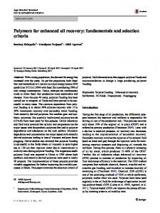
The Vaporizing Gas Drive Mechanism (Figure 1) takes place when a lean gas Go is injected into a crude oil Lo containing a high percentage of intermediate components. In this process, the gas (at the front) is enriched in intermediate components by repeated contacts with the original oil (L0), moving its composition on the dew curve of the phase envelope towards the critical point (CP). As illustrated in Figure 1, the gas may become so enriched with intermediate components that it may become miscible (G3 in Figure 1) with the oil Lo.
INTERMEDIATE
Figure 1. Vaporizing Gas Drive Mechanism. LIGHT
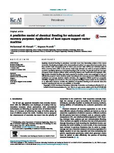
The Condensing Gas Drive Mechanism (Figure 2) occurs when a rich injection gas Go is contacted with an oil that is relatively lean in the intermediate components. In this process, the oil near the injection point (at the rear) is enriched in intermediate components by repeated contacts with the injection gas (Go). The intermediate components of the gas condense into the oil moving its composition towards the critical point. As illustrated in Figure 2, the oil may become so enriched with intermediate components that it may become miscible with the gas.
e.l
I tl
//
//
//
//
//
//
//// / [
//
/ / / I //
// {
HEAVY
INTERMEDIATE
Figure 2. Condensing Gas Drive Mechanism. By definition the lowest pressure at which the oil and the gas phases resulting from a multiple contact process (vaporizing or condensing) between a reservoir crude oil (Lo) and an injection gas (Go) are miscible in any ratio is called the multiple contact minimum miscibility pressure (MMP). 2.2. Classical methods to calculate the MMP
To our knowledge, all the programs available in petroleum companies such as PVTsim (CALSEP MS and DEWPOINT MS), PVT-X (PERA A/S) and the PVT-pack developed by the French Petroleum Company TOTAL [1-2] are not able to determine whether the mechanism taking place is a VGDM or a CGDM. From the user's point of view, both mechanisms have to be successively simulated and the "true" MMP is the lowest value thus determined. From a practical point of view this procedure is time consuming and should be avoided. Moreover, it is sometimes asked to the user to try different algorithms to calculate a given MMP. As a consequence, in many cases, different values of the MMP may be obtained for a given mechanism and the user must, once more, choose the smallest one.
E. Neau et al. / Fluid Phase Equilibria 117 (1996) 2 6 5 - 2 72
267
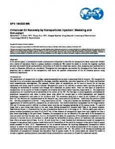
The most currently available algorithms are either the negative flash [3-4] or a cell to cell simulation [5] or one-cell simulation [3]. The accuracy of such methods was checked, using the PVTsim program, by plotting the evolution of the MMP with respect to the enrichment level of an injection gas Go with a Solvent So. Results are shown in Figure 3 where the enrichment level (Enr %) is the mole percent of solvent So mixed with Go in order to define a new injection gas G; this gas is injected in the crude oil Lo at a constant temperature and the MMP is calculated. 350.0
i
I
~
I
I
i
I
I
I
I
350.0
I
....... NEGATIVE FLASH .: CALCL~ATION
~MMP/bar
300.0
,
,
tMMP/bar
300.0
.~
........
2................
i""'.
250.0
.- ....... VGDM ....'" SIMULATION
250.0 i
200.0
SIMULATION
200.0
~
150.0
150.0
T = 369.25 K
T = 369.25 K (a)
100.0
~
0.0
,
~
50.0
~
~
,
(b)
Enr%
,
D
100.0
I00.0
,
0.0
,
,
,
,
50.0
Enr%
,
100.0
Figure 3. Locus of the MMP with respect to the enrichment level at T/K = 369.25. (a) Results of the VGDM, CGDM simulations and of the negative flash calculation. (b) Locus of the minima (true MMP). Table 1. Composition of the different fluids used for MMP simulation (mole percent). Compounds Reservoir Gas Go Solvent Crude Oil Lo So H2S 0.900 1.16 N2 0.083 0.74 CO2 3.463 4.57 Methane 36.459 73.18 Ethane 10.993 12.25 Propane 6.822 4.77 60.0 Isobutane 1.215 0.54 n-Butane 3.716 1.49 40.0 Isopentane 1.576 0.39 Pentanes 2.546 0.50 Hexanes 3.488 0.30 Heptanes 3.649 0.11 Octanes 3.377 Nonanes 2.869 Decanes 2.211 Cu+ 16.633
Table 2. True Boiling Point (TBP) distillation of the reservoir crude oil. Cut Mole percent Molecular Density in reservoir Weight kg.m~ C5 2.546 C6 3.488 C7 3.649 96.0 720.9 C8 3.377 112.0 753.3 C9 2.869 124.0 766.6 C~o 2.211 134.0 777.1 Cu 1.996 147.0 788.6 C~2 1.662 160.0 799.0 C13 1.487 173.0 809.2 C~4 1.239 188.0 820.0 C~5 1.152 205.0 830.6 C~6 0.961 224.0 840.2 C~7 0.821 235.0 845.4 Ct8 0.713 250.0 851.6 C19 0.644 264.0 857.3 C20+ 5.958 435.0 927.7
Tables 1 and 2 show the composition of the different fluids and the results of the crude oil TBP distillation. The PVTsim program was used with Pedersen's characterization of the plus fraction [6] coupled with the Redlich-Kwong-Soave [7] equation of state (EOS) with standard binary interaction parameters [6].
268
E. Neau et al. / Fluid Phase Equilibria 117 (1996) 265-272
As shown in Figure 3a, the change of mechanism from condensing gas drive to vaporizing gas drive for an enrichment level of 3 %, leads to a discontinuity of the true MMP from 255 to 280 bars. With the fluid compositions given in Table 1, the PVTsim program was unable to calculate the MMP simulating a CGDM for an enrichment level higher than 3 %. In the same way, the failure of the VGDM algorithm for enrichment levels close to 75 %, or the surprisingly rapid increase of the calculated MMP at 36 % leads to choose the MMP as the value of 277 bars given by the negative flash method (Figure 3a). Those results seem highly improbable since it is well known that the enrichment of an injection gas by a LPG (Liquefied Petroleum Gas i.e. solvent So) decreases the value of the MMP. 3. A N E W
ALGORITHM
3.1. The proposed
FOR ENHANCED
OIL RECOVERY
CALCULATIONS
method
The algorithm proposed in this paper allows us to determine directly the MMP without simulating successively a VGDM and a CGDM. It is based first, on the determination of the mechanism (CGDM or VGDM) and then is followed by an accelerated successive contact simulation. In order to determine the proper mechanism, the first step of the method consists in determining the FCMP (First Contact minimum Miscibility Pressure) i.e. the lowest pressure where the injection gas Go and the crude oil Lo are first contact miscible. This pressure may be determined by simulating a swelling test and locating the stationary point at the top of the P-X diagram as shown in Figures 4a and b. In such a diagram, the amount of injected gas, noted as X~, is defined
by: number of moles of gas Xga~ = number of moles of gas + number of moles of reservoir crude oil
(1)
At the FCMP, the segment [Lo-Go]joining the composition of the crude oil and of the gas is tangent to the phase envelope. Consequently, the segment [Lo-Go] intercepts the P-X diagram either on the bubble curve or on the dew point curve; it is then established that the mechanism taking place is thus respectively a CGDM (see Figure 4a) or a VGDM (see Figure 4b). 1000. 1000. P = FCMP
Pc
.
.
.
.
.
.
.
.
.
.
.
.
.
500.0-
.
dew point curve
/
- .....
// "~I
bubble point curve dew point curve
//
II
Ca) / /
/i
500.0 Pc
............................
0.0
'
/
/~P
', '
I I P I
,
//'r-,\ ]GO
I~
/
il t I I J
0.0
P = FCMP
L~
cp
.
pointcurve/
bubble
.....
.
/bar
,
,
Xg~
X$~ 'X'c
' XvCMVl.O0 0.00 0.50 XFc~X'c 0.0( Figure 4. P-X curves as obtained during a swelling test. (a) CGDM • the stationary point (top of the curve) is located on the bubble curve. 0a) VGDM : the stationary point is located on the dew point curve.
In a second step, at various pressures lower than the FCMP (in fact lower than the critical pressure, Pc, in the P-X diagram), multiple contacts are performed between : - the reservoir crude oil Lo and successively the injection gas Go and the equilibrium gases Gi, G2..... Gn in the case ofa VGDM (see Figure 1). - the injection gas Go and successively the reservoir crude oil Lo and the equilibrium oils L1, L2..... Ln in the case of a CGDM (see Figure 2).
E. Neau et al. / Fluid Phase Equilibria I 17 (I 996) 265- 272
269
3.2. Reduction of the contact number. In order to accelerate the previous algorithm i e to reduce considerably the number of contacts, different solutions are proposed : LIGHT
a) Choice of the mixing proportions : In the case of a vaporizing gas drive mechanism (see Figures 1 and 5), for each contact k (k = 1, 2, ..., n), the equilibrium gas Gk is determined as the gas phase in equilibrium with the oil Ls.k (see Figure 5) obtained by saturating the oil L0 with the equilibrium gas Gk_~ obtained at the previous contact. After several contacts it is checked whether the oil Lo and the gas Gk are miscible (the pressure is greater than MMP) or the equilibrium phases Ls.kand Gk are always the same (the pressure is lower than MMP). MMP is then determined by a simple dichotomy. A similar procedure is applied in the case of a condensing gas drive mechanism.
1/I
//~
~,~ ~;P criticaltieline~
HEAVY
INTERMEDIATE
Figure 5. Reduction of the contact number using optimal mixing proportions (case of a VGDM).
b) Calculation of a criticit~ parameter 2e: Even when the mixing proportions are optimal, it is sometimes difficult to know, when the contacts are performed at a pressure close to the MMP, whether the composition of the fluids in equilibrium (Ls,n-G,) are slowly converging towards a limiting tie line or miscibility can be finally achieved. In order to determine rapidly whether the miscibility will be achieved or not, we propose to follow the evolution of the coefficients K 1. XLo(i) , X L f ( i ) a n d YGf(i) are respectively the mole fractions of component i in the reservoir crude oil L0, the final oil Lf (see Figure 7) and the final gas Gf obtained after many contacts between Lo and Go. When the pressure is equal to the MMP, the limiting tie line is merged with the critical tie line, INTERMEDIATE whereas above the MMP (see Figure 1) no limiting tie HEAVY Figure 7. Limiting tie line obtained at a pressure line passing through Lo exists. Equations 3 are solved lower than the MMP for a VGDM. for different pressures, and the lowest pressure for which no solution is found is the MMP.
E. Neau et al. / Fluid Phase Equilibria 117 (1996) 265- 272
271
The main problem with such an algorithm is that a tie line passing through the composition of Lo can be found, even if the pressure is above the MMP. This occurs in many cases for real petroleum fluids described by more than three components. As a consequence, it is impossible to define in a general way the MMP as the lowest pressure for which equations 3 can not be solved. This definition is accurate only for real three component mixtures or in very precise cases for real petroleum fluids. The negative flash must be used only in theses special cases. In ternary systems, the phases Lk and Gk in equilibrium (for instance [G1-L~] and [G2-L2] in Figure 7) are converging towards the critical point respectively on the bubble and the dew curves when the contacts are performed according to the appropriate mechanism. In this case, the function ~.~ defined by equation 2 is an increasing function converging asymptotically to one. However, Figure 6b shows clearly that it is no more the case when the fluid is described by more than three components. In such systems, for a pressure lower than the MMP, during the first contacts the phases in equilibrium are converging towards a critical point i.e. the liquid and gas phase compositions become more and more similar and the kp function is increasing. During the next contacts, the phases in equilibrium are moving away from the critical point since the ~.p function is decreasing (see Figure 6b). This effect can also be seen in Figure 6a where the difference between the densities of the phases in equilibrium is increasing. It must be noted that this behavior is impossible for a real ternary system. This fundamental difference between a ternary and a multi component system allows one to explain why the negative flash can find a solution at a pressure higher than the MMP and sometimes higher than the FCMP. More information concerning quaternary systems is given in the recent paper [9] by Johns et al. In Figure 6b, at pressures lower than the MMP (dashed lines), after a few contacts the ~.p function remains constant indicating that a limiting tie line has been reached (see for example pressure P2). This limiting tie line can be reached either using a contact simulation as previously described or using a negative flash algorithm. When the pressure is higher than the MMP, after a few contacts the equilibrium gas becomes miscible with the reservoir crude oil L0. A one phase system is obtained and the contact simulation is not able to reach the decreasing part of the ~.p function. However initializing the negative flash at the compositions corresponding to the limiting tie line found at a pressure just below the MMP equations 3 can be solved explaining why the estimated value may be much more higher than the one obtained using a contact simulation. As a conclusion the use of the negative flash algorithm alone cannot be considered as a trustful method for determining whether an oil and a gas are multiple contact miscible or not. However, in a few scarce cases, a real multi component system may have the same behavior as a real three component system i.e. kp is an increasing function of the contact number. In this case, and in this case only, the negative flash can be used to find the MMP. 3.3. Comparison with usual methods to calculate the MMP The proposed method was tested, to calculate the MMP with respect to the enrichment level of the injection gas as previously made using PVTsim The results obtained are illustrated in Figure 8 and must be compared to those of Figure 3. Nothing has been changed (same characterization procedure, same EOS), except the algorithm. Figure 3a shows that with classical methods, the true miscibility mechanism is a CGDM when the enrichment level is lower than 3 %. Above 3 % the forward mechanism (VGDM) could only be simulated. Such a result was surprising since the injection gas Go contains a very high percentage of methane and the reservoir oil is rich in intermediate components. Moreover, when the enrichment level increases, the fraction of butane in the injection gas G becomes higher and it could be expected to lead to a CGDM for high values of the enrichment level. Figure 8 shows clearly that the method developed in this work is in perfect agreement with the expected behavior : the locus of the calculated MMP is a monotonous decreasing function of the enrichment level. The mechanism taking place is first a VGDM (when the enrichment level is lower than 63 %) whereas for significant values of the enrichment (Enr % > 63 %), the CGDM becomes more propitious. The algorithm developed in this paper has been used with a complete success to simulate more than one thousand MMP or MME (Minimum Miscibility Enrichmen0 with reservoir crude oils, gases and solvents very different from those presented in this study.
272
E. Neau et al. / Fluid Phase Equilibria 117 (I 996) 265-272
350.0
I
I
I
~
I
I
I
I
I
CGDM
VGDM
~MMP/bar
300.0 250.0 200.0 150.0
\ 100.0 \ 50.0 Enr % 0.0
I
I
I
I
I
I
0.0 50.0 100.0 Figure 8. MMP calculation as a function of the enrichment using the method developed in this work. 4. CONCLUSION
A method was proposed to calculate accurately the MMP. The procedure consists in determining directly the mechanism taking place (condensing or vaporizing), and then in performing successive contacts (backward or forward) between a crude oil and an injection gas. Particular efforts were devoted to the decreasing of time calculation using optimal mixing proportions and a function, noted gp, especially efficient at pressures close to the MMP. Moreover, when gp is a strictly increasing function of the contact number a negative flash algorithm is used. The continuous evolution of the estimated MMP in the case of the enrichment of an injection gas with a solvent illustrates the efficiency of the proposed method. ACKNOWLEDGMENT
The authors gratefully thank Professor A. P6neloux for helpful discussions and the French Petroleum Company TOTAL for sponsoring this research. REFERENCES
1. G. Auxiette and I. Chaperon, SPE of AIME, 10271 (1981) 1. 2. G. Auxiette and I. Chaperon, Second European Symposium on Enhanced Oil Recovery. Pads, November 8ll, (1982). 3. F. Jensen and M.L. Michelsen, 4th European Symposium on Enhanced Oil Recovery. Hamburg, October 2729, (1987). 4. C.H. Whitson and M.L. Michelsen, Fifth International Conference on Fluid Properties & Phase Equilibria for Chemical Process Design, Banff, Alberta, April 31 -May 5, (1989). 5. K.S. Pedersen, J. Fjellerup, P. Thomassen, Aa. Fredenslund, 61 't Annual Technical Conference and Exhibition of the SPE, New Orleans, October 5-8, (1986). 6. K.S. Pedersen, Aa. Fredenslund, P. Thomassen, Gulf Publishing Company, Contributions in Petroleum Geology & Engineering 5, (1989). 7. G Soave, Chem. Eng. Sci., 27 (1972) 1197. 8. A.A. Zick, SPE 15493 (1986) 1. 9. R.T. Johns, B. Dindoruk, F.M. Orr, SPE/DOE, 24112 (1992) 83.