discrete multilevel monitoring system (MLS) (the Water FLUTe) for temporary or permanent ...... Canada. Editor's Note: The use of brand names in peer-reviewed.
A New Depth-Discrete Multilevel Monitoring Approach for Fractured Rock by John A. Cherry, Beth L. Parker, and Carl Keller
Abstract A new approach for monitoring in fractured rock was demonstrated in a contaminated (trichloroethylene and metolachlor) dolostone aquifer used for municipal water supply. The system consists of two related technologies: a continuous packer for temporary borehole seals (Flexible Liner Underground Technologies Ltd. [FLUTe] blank liner) and a depthdiscrete multilevel monitoring system (MLS) (the Water FLUTe) for temporary or permanent monitoring. The continuous borehole liner consists of a urethane-coated nylon fabric tube custom sized to each hole. The FLUTe MLS consists of the same liner material with many depth-discrete intervals for monitoring hydraulic head and/or ground water quality. The FLUTe blank liner seals the entire borehole, prior to FLUTe multilevel installation, to prevent vertical cross connection while allowing borehole logging and testing. The FLUTe multilevel system also seals the entire borehole with the exception of each monitoring interval where the formation water has direct hydraulic connection to the pumping system via a thin permeable mesh sandwiched between the liner and the formation. The blank sealing liners and the multilevel systems were used in five boreholes ranging in diameter between 9.6 and 14.5 cm in the dolostone aquifer to depths of 150 m. The systems were custom designed for each borehole and included between 12 and 15 monitoring intervals. The application demonstrated the ease of installation and removability and facilitated obtaining large data sets with minimal labor. The system offers unique and versatile design features not possible with other bedrock monitoring devices and has been used at many bedrock contamination sites across North America.
Introduction Depth-discrete multilevel monitoring in a borehole is the use of an engineered system for measurement of hydraulic head and/or ground water sampling at several or many depth-discrete intervals. A seal is positioned above and below each monitoring interval to prevent hydraulic connection between intervals. The goal of such multilevel monitoring is to achieve, using a single hole, what would otherwise be accomplished with a cluster of monitoring wells each completed to a different depth and each installed in a separate borehole. Multilevel monitoring minimizes formation disturbance by drilling fewer holes and decreases cost per monitoring zone. Depth-discrete multilevel monitoring, henceforth termed multilevel monitoring in this article, has a long history in contaminant hydrogeology, starting with systems used in studies of ground water contamination in permeable unconsolidated deposits (Merritt and Parsons 1960; Pickens et al. 1978; Cherry et al. 1983).
Copyright ª The Author(s) Journal compilation ª 2007 National Ground Water Association.
Multilevel monitoring systems (MLSs) are particularly advantageous for investigations in fractured rock because the need to maximize the quantity and diversity of data acquired from each hole is driven by high drilling costs. Also, the expectation of fracture network complexity drives a need for data from many depths in each hole. In the late 1970s, Westbay Instruments Inc. (www.westbay.com) developed the first commercially available MLS suitable for fractured rock. The utility of this system, described by Black et al. (1986), has been well established by many fractured rock applications around the globe. Cherry and Johnson (1982) developed a second type of MLS for fractured rock, which was subsequently redesigned and made commercially available globally by Solinst Canada Ltd. in the late 1980s as the Waterloo-Solinst system (Pianosi and Weaver 1991; Dunnicliff 1988; www.solinst.com). This article describes a new approach for monitoring contaminated sites in fractured rocks. This approach comprises two related technologies: the first is a continuous flexible packer (i.e., borehole liner) used temporarily for complete borehole sealing to prevent borehole cross connection prior to installation of the MLS, and the second, which incorporates attachments to the liner, is a removable MLS for temporary or long-term monitoring of hydraulic
Ground Water Monitoring & Remediation 27, no. 2/ Spring 2007/pages 57–70
57
System Components and Installation Procedure
head and/or water quality. This new system is different than the Waterloo-Solinst and Westbay systems, allowing it to accomplish multilevel monitoring in ways and circumstances not otherwise possible. This approach was initially developed by Flexible Liner Underground Technologies Ltd. (FLUTe) in the late 1990s and evolved to its present design by refinements based on experience at many field sites (www.flut.com). The design and operation of the borehole liner and FLUTe MLS is presented herein along with a description of their performance at a site where trichloroethylene (TCE) and a pesticide, metolachlor (MET), occur in a fractured dolostone aquifer used for municipal water supply in Cambridge, Ontario. The precursor for the FLUTe ground water method was a patented version of the flexible liner technology known as the SEAMIST� system developed by Carl Keller for vadose zone monitoring beginning in 1991. The FLUTe method has been used at many fractured rock sites; however, the technology was pushed to its limit at the Cambridge, Ontario site, which resulted in major design improvements in response to the field experience. At this site, exceptionally large data sets were produced by taking full advantage of the capabilities of the method. The Cambridge site is used by the University of Waterloo to develop and assess methods for investigating ground water contamination in both overburden and bedrock. At the same site, a modified version of the Waterloo-Solinst system is being used for investigations in the overburden (Parker et al. 2006). An early version of the FLUTe system was first used in the dolostone at the site in 2000 to 2001. An improved version was used beginning in 2002, and a version with additional improvements was used beginning in 2004. By 2005, five holes were equipped with FLUTe multilevel systems. A) Liner is clamped on and installation begins
Inverted liner Water Clamp
Reel
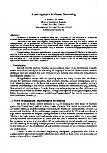
Each component of the FLUTe multilevel system, also called the Water FLUTe� system, is attached to the borehole liner, making it the fundamental component of the multilevel system. The liner is made from impermeable, tubular, and flexible nylon fabric slightly larger than the borehole and it extends from the top to the bottom of the hole. The liner is inflated when the water level inside the liner is positioned a few meters above the hydraulic head in the zone of highest head in the hole. On its own, without any attachments, the blank liner performs as a complete seal like a continuous packer in the hole. When used in this manner, the blank liner prevents hydraulic cross connection in the hole. When ports for water sampling and/or hydraulic head monitoring are attached to the liner, the system performs as a depth-discrete MLS. The procedures for installation and removal are the same for both the blank liner and the MLS. The blank liner and also the multilevel system are installed using a procedure known as eversion: a process whereby the tubular liner turns from being inside out to being right side out as it descends down the hole. Figure 1 shows the four main stages in the installation procedure. In the first stage (Figure 1A), the reel on which the liner is shipped from the manufacturing facility to the field site is positioned close to the surface casing onto which the top of the liner is clamped. The surface casing normally extends through the overburden and/or rock rubble into competent rock. In this first stage, the liner is pushed by hand down into the casing (~1 m) to form an annular pocket in which water is then added to drive the liner farther down the hole (Figure 1A). Addition of water into this initial handformed pocket causes continuous propagation of the liner down the hole.
B) Liner begins C) Liner is halfway advancing below down the hole standing water in hole Inverted liner
D) Liner is completely everted
Reel
Water
Surface Casing Open borehole static water level
Water
To reel Inverted liner Excess headin liner
Tether tied to liner bottom
Liner
Open fractures Open hole
Liner installation sequence
Figure 1. Stages in installation of blank liner: (A) liner is clamped to casing head and pushed by hand a few feet down the casing before water is added, (B) the liner goes below the standing water level in the hole, which pushes water into the formation, (C) the liner is halfway down the hole at which point only the tether remains on the reel, and (D) the liner is completely everted in the hole and the water level inside the liner is raised a few meters or more above the static water level measured in the open hole prior to liner installation; this excess head causes inflation of the liner to seal the borehole.
58
J.A. Cherry et al./ Ground Water Monitoring & Remediation 27, no. 2: 57–70
In the second stage, continued addition of water causes the liner to descend below the standing water level in the hole, and as it goes deeper, the liner causes expulsion of water from the hole into the formation (i.e., into fractures; Figure 1B). In effect, the installation procedure is a progressive large-scale slug test because at each point in time, the rate of liner descent is governed by the transmissivity of the open-hole segment below the bottom of the liner. The length of this open-hole segment decreases as liner installation proceeds, and if the hole has substantial transmissivity all of the way to the bottom, installation of the liner is typically completed within 1 to 2 h. However, if the hole has low transmissivity throughout or in the bottom parts, the installation can take many hours or even several days. This longer time is usually not detrimental because only minimal labor is required during periods of slow liner descent, which involves periodic checking and perhaps topping off the water level inside the liner. If faster installation is desired, a water removal tube, typically 1- to 2-cm inner diameter (ID), is inserted deep in the hole before liner installation starts. With this tube in place, liner descent is accelerated by pumping water from this tube situated between the liner and the borehole wall. The tube is withdrawn after the liner reaches the bottom of the hole. To allow tube removal, the water level inside the liner is lowered to cause liner deflation and then the water level is raised to reinflate the liner after the tube is withdrawn. The halfway point of the liner installation is achieved when the bottom end of the liner (i.e., the tubular roll) is completely off the reel and the bottom end of the liner is positioned at the top of the casing (Figure 1C). At this halfway point, only the tether line remains on the reel. As the liner continues to go down the hole, the tether rolls off the reel and also goes down inside the liner. The main purpose of the tether is for removal of the liner from the hole, if removal is desired later. The liner installed in each hole is generally constructed to the hole length; and therefore, when the bottom of the liner reaches the hole bottom, it is fully everted (Figure 1D). Because the liner is everted in the hole rather than just lowered down the hole, no part of the outside of the liner contacts the borehole wall until it everts. Therefore, there is no rubbing or scraping along the borehole wall. Rubbing or scraping is also avoided when the liner is removed because removal is just the opposite of the installation process, except that water is pumped from the liner interior while tension is applied to the tether. The MLS is constructed by creating attachments outside and inside the liner to allow formation water from depth-discrete segments to pass through the liner into pump systems. Specifically, monitoring intervals are formed by bonding different materials to the liner. For simplicity, Figure 2 shows a single monitoring interval with a double check–valve pump system for sampling the interval. In this version of the system, the hydraulic head in the monitoring interval is determined manually using a standard water level tagline. In another version of the system, a pressure transducer is positioned on the port-pump tube, just below the first check valve, with the cable extending to ground surface inside the liner. Each monitoring interval is formed by a thin flexible spacer (Figure 3), attached by
Pump quick connect Surface Casing
Tether support of tubing bundle Formation head in pump Sealing liner Spacer defining monitoring interval Port behind spacer thru liner Sample tube (0.17 in ID) Pump tube (½ in ID) Second check valve Bottom of the U First check valve Port to pump tube (0.17 in ID)
(Single port system shown for clarity)
Figure 2. The port and pump system in the FLUTe multilevel system; for clarity, only one port and pump system are shown; however, actual FLUTe systems contain multiple ports. In the system illustrated here, hydraulic head is determined by lowering a conventional water level probe down the pump tube. Or, in an alternative design, a dedicated pressure transducer is connected to each port.
heat welding on the outer surface of the liner, to create a segment of the borehole not sealed by the liner. The spacer is constructed using a permeable mesh cut to the desired length of the monitoring interval and that runs continuously around the circumference of the borehole. The mesh forms a very pervious but thin (1- to 2-mm) annulus between the liner and the hole wall, and it intersects all ground water flow paths that encounter the borehole wall in the interval. Figure 3 shows the perforated tube that conducts the formation water from those flow paths to the port through the liner. A thin outer filter fabric composed of finely woven nylon or polyester is stitched to the spacer to prevent particles of 200 lm or larger (e.g., sand or coarse silt) from going through the port into the pumping system. Because the combined thickness of the spacer composite is so small (less than 2 mm), the spacer has almost no storage volume, and therefore, minimal purging is required to draw fresh formation water into the plumbing in the interior of the liner. Figure 4 shows the port with a dedicated gas-driven, double-valve pump. The port behind the permeable spacer connects through the liner to a tube called the ‘‘port tube’’ that descends to the bottom of the liner in an interior sleeve of the liner. The port tube rises up to the bottom end of the J.A. Cherry et al./ Ground Water Monitoring & Remediation 27, no. 2: 57–70
59
A
Side cut view
Gas bottle
Central tubing bundle Spacer material between liner and filter fabric Formation
3 way valve
Filter fabric on outer surface of spacer
Sample container Gas/water interface before purging stroke
Liner
“Pump tube” Monitoring interval
Perforated tube in spacer material Feed-through sealing tube through liner
Water filled liner
B
“Sample tube” “Port tube”
Port-to-pumptube
Sleeve on liner containing tube to pump
Cross cut view Liner Spacer Filter fabric
Buffer against aeration
Gas/water interface at end of sample stroke “Bottom of the U” First check valve (closed)
Liner water fill
Figure 3. Details of the spacer design and other aspects of the monitoring port: (A) vertical cross section through centerline and (B) horizontal cross section.
Figure 4. Procedure for purging and sampling the FLUTe gas-driven, double-valve pump system. The pump system yields water when gas pressure is applied to the pump tube (large diameter), which drives the water in the pump tube to surface via the sample tube (smaller diameter). During this water yield period, the first check valve is closed and the second one is open. When the gas pressure application stops, the flow stops and the second check valve closes, causing storage of water in the sampling tube until the next application of gas pressure.
pump at the first check valve. The port tube does not go directly up from the port to ground surface but rather goes down to the bottom of the liner and then up to the pump. This check-valve pump design is unique to the FLUTe system when compared to other gas-driven, check-valve pumps used in other multilevel systems and monitoring wells. The advantage of this down-then-up configuration is that, regardless of the port elevation, the pump length is the same for each port. Therefore, the pumping volume per unit stroke is much larger than that produced by other types of dedicated gas-driven downhole pumps. The FLUTe pumping system allows simultaneous purging of FLUTe pumps connected to several ports. The water flowing from the spacer enters the pump tubes through the first check valve and fills the pumping system to the level of the hydraulic head in the formation at each spacer. The check valve has a Teflon� ball, but no spring, to provide the minimum impedance to the equilibration of the water level in the pump tube with the water level in the formation after purging. This equilibration allows for the manual water level measurements of hydraulic head. Thus, calibration of pressure transducers attached to each port can be checked after installation, or the system can be used without pressure transducers. The pump system consists of the two tubes to the surface forming a very long U shape (Figure 4). The large tube, called the ‘‘pump tube,’’ is typically 0.5-in (1.27-cm) ID. The other leg of the U is a smaller diameter tube,
typically 0.17-in (0.43-cm) ID, referred to as the ‘‘sample tube.’’ A second check valve is often included in the sample tube near the bottom of the pump U bend. The second check valve usually contains a stainless steel ball without a spring. The primary advantage of the second valve is the improved pumping efficiency by preventing backflow into the pump tube as it is refilling with water. The second valve is also useful for relatively shallow holes and for use with flow-through devices where water quality monitoring occurs at ground surface prior to sample collection. The disadvantage of the second check valve is that it increases the complexity of the pumping system and it requires that the system be purged of water prior to obtaining a manual water level measurement. The pump tube systems for the Water FLUTe ports are connected and supported with Kellum� grips attached to the central tether. The entire tubing bundle is wrapped in a diagonally woven sheath. In this compact, snakelike form, it passes easily into the liner during the installation procedure. A 1.27-cm-ID tagline tube is included in the tubing bundle to facilitate manual measurement of the water level inside the liner. The entire tubing system from the spacer to the surface is generally made of polyvinylidene fluoride (PVDF) tubing but other tubing, such as nylon, has been used on some systems. All systems produced before 2002 used nylon tubing. The fittings are usually brass unless stainless steel or another material is specified.
Port-to-pump tube in spacer Central tubing bundle containing pumps, etc..
60
J.A. Cherry et al./ Ground Water Monitoring & Remediation 27, no. 2: 57–70
Liner Provides Borehole Seal The liner is pressed tightly against the borehole wall when the water level inside the liner is kept a few meters or more above the highest head in the formation. The liner is custom built to the diameter specified for each hole and is generally sized slightly larger (i.e., 3 to 4 mm) than the nominal hole diameter so that the liner, when inflated, can easily expand into borehole wall irregularities. Borehole televiewer images taken inside a liner at the Cambridge site and other sites show that the liner conforms to wall irregularities, as shown in Figure 5. The video snapshot shown in Figure 5A is the borehole wall at approximately 53-m depth without the liner. The second snapshot is with the liner at about the same elevation (Figure 5B). The slight elasticity of the liner and the eversion process of installation allow the liner to conform very well to the irregularities of the borehole wall as evidenced by the similarities of the two photographs. Some boreholes have enlargements or cavities that are too large for the liner to fill by expansion. While the zones themselves are not sealed by the liner, seals do form at the necks above and below these zones (Figure 6), preventing the enlargements or cavities from jeopardizing the overall integrity of the borehole seal. In the cavities or enlargements, the liner is not in contact with the borehole wall, i.e., unsupported liner. An essential property of the liner is that it is sufficiently strong to prevent rupture in those zones where the borehole wall has a much larger diameter than the liner. Liner burst tests conducted in the laboratory show that the typical unsupported liner can withstand an excess internal pressure up to 448 kPa (~45 m of head differential between inside and outside the liner). Though, failure pressure is inversely proportional to the diameter of the borehole. The capability of the liner for crossing cavities makes both the blank liner and FLUTe multilevel system suitable for use in karst. Reinforced sections of the liner or a stronger fabric can be used where video logs indicate large voids or sharp ledges that could cut the fabric. If the depth to water in the borehole is too close to ground surface to allow the recommended 3-m differential for normal inflation, the interior water level can be increased by extending the liner as a column above ground surface or a weighted bentonite slurry can be used instead of water to fill the liner. Laboratory tests show that a 3-m
head differential provides sufficient seal for the typical range of borehole diameters (< 10 inches) and hazards, such as sharp edges, without overloading the liner. The heavy bentonite slurry fill was used in 13 liners in 2004 and 2005 to deal with shallow water table or artesian conditions. The liner is still removable where the bentonite slurry fill has been used. Application of a head differential within the range recommended previously is not always sufficient to achieve a complete seal in each interval between monitoring ports because, in some situations, hydraulic head much higher than the open-hole static level can occur at particular zones. The open-hole water level is a blended water level dependent on the hydraulic conductivity and hydraulic head distribution throughout the hole. Prior to installation of the multilevel system, the depth of highest head in the hole and the magnitude of this head are unknown. However, after the multilevel system is installed and head measurements are obtained, the presence of zones of higher head can generally be deduced from the head profile, and higher inflation pressure can then be applied incrementally until the head differentials for each of the ports are approximately 3 m. In the case of hydraulic testing where large drawdowns are created by pumping nearby wells, the potential for seals to be compromised and for liner ruptures to occur is increased and needs to be heeded during designs of such tests.
Water Sampling Using the Double-Valve Pump The most commonly used version of the FLUTe multilevel system has four or more monitoring ports with a double-valve pump attached to each port. The largest number of double-valve pumps used in a FLUTe multilevel system is 15 at the Cambridge site. For simplicity, Figure 2 shows a system with only one port. In FLUTe multilevel systems using dedicated pumps for multiple ports, the pump system of Figure 2 is replicated in the liner interior to match the number of ports. At sites where the formation hydraulic head is close enough to ground surface for suction pumps (e.g., peristaltic pumps) to be effective, the double-valve pumps are not required but provide a more convenient sampling method. The double-valve pump operates as follows. After the pump tube has filled with water, a pressure source such as
Figure 5. Borehole television images taken in a hole in the dolostone aquifer at the Cambridge site: (A) image at a depth of approximately 53 m bgs without the FLUTe liner and (B) image inside the liner at approximately the same depth. Both images clearly show irregularities on the borehole wall, indicating that the liner conforms to the irregular wall surface (liner expands slightly to press into the borehole wall depressions). J.A. Cherry et al./ Ground Water Monitoring & Remediation 27, no. 2: 57–70
61
Figure 6. Illustration of the behavior of a FLUTe liner during installation; as the liner descends through a breakout, it expands but cannot expand sufficiently to press against the breakout wall. The liner is then unsupported in this interval, but once the liner goes below the breakout, it once again presses against the entire circumference of the borehole. E1 ¼ liner in normal size hole, E2 ¼ liner expands where hole is larger, E3 ¼ liner cannot expand to fill breakout, so liner is unsupported but does not break unless excess head is applied, E4 ¼ liner entering normal size hole, and E5 ¼ liner proceeds down normal size hole.
a nitrogen tank (Figure 4) is connected to the top end of the pump tube. A ‘‘purge pressure’’ is applied from the standard nitrogen tank to the gas/water interface at the standing water surface in the pump tube. The applied purge pressure is great enough to force the interface to the bottom of the U and up the sample tube to the surface, thereby expelling essentially all of the water from the entire pumping system for that port. Only residual droplets are left in the sample tube. Then the pressure is dropped in the pump tube and the system is allowed to refill with formation water from the spacer via the port tube. The residual droplets are swept up by the recharge of the pump and sample tubes. The volume of the pump tube is usually far greater than that of the port tube plus the interstitial space in the spacer. Hence, upon the first recharge of the pump, some formation water adds to the fill of the pump tube through the first check valve during this first recharge. A second application of the purge pressure, referred to as a stroke, forces all of the water out of the pumping system again. This second purge stroke volume is discarded along with the first purge volume. The pressure in the pump is dropped again to atmospheric pressure, allowing the pump tube to refill for the second time. This second recharge volume is essentially all formation water. In the next stage, called the sampling stroke, the pressure at the gas source is lowered to the ‘‘sampling 62
J.A. Cherry et al./ Ground Water Monitoring & Remediation 27, no. 2: 57–70
pressure.’’ This pressure is prescribed for each Water FLUTe system and is sufficiently low that the gas/water interface can only be driven down to within 6 to 10 m of the bottom of the U bend. As the water for this stroke is driven out of the sample tube at the surface, a recommended volume of the first flow is discarded because it may contain aerated droplets from the last purge stroke. The sample is collected from the subsequent flow. As the interface in the pump tube approaches its lowest level, the flow rate from the sample tube slows dramatically for easy sample collection. The typical continuous flow volume for a single stroke from which the sample can be obtained exceeds 6 L, including 0.5 to 1 L for the discard, depending on the depth of the borehole and water table. The water sampled using this procedure essentially comes from the lower three quarters of the pump tube. If more sample water is desired, the pump pressure is dropped for another recharge. When applying the sample pressure again, there is no need to discard the first flow. The sample cycle can be repeated until no more sample water is desired or until the pump has extracted a sufficient volume of water to collect a sample from the desired distance away from the borehole. If desired, the flow from the sample tube can be directed under near steady-state conditions through a chamber with probes for measurement of chemical parameters such as pH, dissolved oxygen, and electrical conductance as commonly done during low-flow sampling. Water from the two initial purge strokes should not be used because it includes water that may have resided in the pump tubing for long periods of time and could have contaminant concentrations nonrepresentative of the formation water. A distinct advantage of the FLUTe system compared to all other multilevel systems is that all ports can be purged and sampled at the same time with ease. Due to the U-tube design, the tubing length and purge volumes are essentially the same regardless of port elevation except for the hydraulic head differences between ports. Nevertheless, the tube systems can be purged and sampled with the same ‘‘purge pressure’’ and ‘‘sample pressure’’ requiring about the same time to sample all the ports simultaneously. In other words, it takes nearly as much time to purge and sample one port as it does to purge and sample all the ports in the system. Five to 15 minutes of continuous flow is available depending on how rapidly the pressure is applied during one sample stroke. By purging all ports at the same time, the hydraulic heads in all ports are disturbed by a similar amount minimizing the accentuation of transient vertical gradients and resultant vertical redistribution of water in the formation due to sampling. The tubing diameters and simple geometry make the system resistant to clogging even for sites with high turbidity.
Application of the FLUTe Method to the Cambridge Site The field site is located in an industrial part of Cambridge, Ontario (Cambridge site), where pesticide contamination, MET, in the overburden and the bedrock (Silurian dolostone) was discovered in 1993 beneath an agrochemical packaging and distribution facility. A network of conventional
monitoring wells was established in the overburden and in the bedrock during a major investigation in 1993 to 1995 (Carter et al. 1995). All of these wells are in the upper half of the 94.5-m-thick dolostone unit. During this initial investigation, TCE was also discovered in the ground water. A follow-up study showed that the source of the TCE is a nearby industrial site. The investigations reported here, which began in 1999, focus on monitoring in the dolostone. In the current study in which multilevel monitoring is the thrust, the goal is to monitor ground water quality from top to bottom in the dolostone aquifer and also in the upper part of the underlying shale aquitard. The previous study showed that MET and TCE contamination is present in the upper half of the dolostone (Carter et al. 1995) and no information was obtained from greater depth. The study area is situated in the vicinity of several municipal wells that supply water to the city of Cambridge. Therefore, comprehensive knowledge of the spatial distribution of chemical constituents relevant to water quality in the aquifer is needed. Five Water FLUTe systems have been installed in the bedrock to date and more installations are anticipated. In each hole in which a Water FLUTe has been installed, a FLUTe liner was used prior to the installation to minimize borehole short-circuiting and to allow high-resolution temperature logging inside the liner. Borehole logging inside FLUTe liners offers opportunities for characterization of natural-gradient flow conditions without the openhole dominating flow conditions. Furthermore, it ensures an open stable hole for logging with downhole tools, but this must be done with care to avoid entanglement with the tether line. This is particularly important to protect against potential downhole loss of active radioactive sources associated with neutron and gamma-gamma logs. The liner system does not interfere with the use of high-resolution temperature and natural gamma tools, and prospects for application of the full wave form of acoustic televiewer appear to be good. In addition, transparent liner material has been used to facilitate video logging of borehole walls. At the Cambridge site, the liners were removed on occasions when borehole geophysics, straddle-packer testing, and borehole-flow metering were conducted but reinstalled to minimize the cross connection due to open borehole flow. Thus, comprehensive data sets pertaining to
lithologic and ground water flow conditions were used to custom design the Water FLUTe system for each hole. The resultant FLUTe depth-discrete monitoring systems were used to determine the spatial distributions of a wide variety of chemical constituents, including chloride from road salt, nitrate from sewage, TCE, and MET. Each contaminant has a different source location and input condition, resulting in different contaminant concentration distributions. There is no basis for presupposing where the highest concentrations of each contaminant will likely occur in any hole. Therefore, achieving a maximum number of monitoring intervals in each hole is desirable. The length and position of each port, and hence seals, should be based on geologic and hydrologic information obtained from each hole (i.e., core descriptions, geophysical, and/or hydrogeophysical logs that provide information on lithology, fracture, and flow distributions). The diameter of the borehole is the factor limiting the maximum number of monitoring intervals that can be accommodated in the FLUTe system. In this investigation, the first hole was drilled using an air-rotary, water-well rig. The borehole had a nominal diameter of 14.3 cm (5.63 inches). The Water FLUTe installed in this hole contained 15 dual-purpose monitoring intervals. A nitrogen drive, double-valve pump, and a pressure transducer (Solinst /Geokon 4500H, Georgetown, Ontario, Canada) were attached to each of the 15 ports. This first hole extended to a depth of 100 m below ground surface (bgs) (70 m below top of rock), and the 15 monitoring intervals were distributed over the depth interval between 9 and 73 m below top of rock. Figure 7 shows the multilevel system coming off the reel and going down the hole and a view of the wellhead after the system was fully installed and ready for use. From the sampling of this Water FLUTe system and rock core–contaminant analysis performed in 2000 to 2001, it was found that MET and TCE contamination occurred at all monitoring depths. It was then decided to obtain borehole logging data and rock core analyses in the bottom part of the dolostone and in the upper part of the underlying shale. Therefore, the FLUTe system was removed after more than a year of monitoring. The deeper drilling was done in 2003, after which the reconstructed Water FLUTe system with the same configuration of ports was replaced in the hole to continue collection of temporal data. The replacement Water FLUTe used the
Figure 7. Photographs taken at the first installation at the Cambridge site in 2000 showing (A) the FLUTe multilevel system coming off the reel and going down the hole, while water from a hose is added to the system and (B) the wellhead unit for monitoring the 15 ports set up after installation of the multilevel system. J.A. Cherry et al./ Ground Water Monitoring & Remediation 27, no. 2: 57–70
63
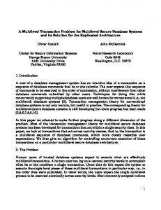
to user demand. Figure 8 shows representative results from pressure transducers recorded over a 2-week period in 2000. Only the shallowest port and the deepest port are shown; all of the other ports provided the same temporal trends with hydraulic head at positions between the two shown on this figure. The transducer records show that there is a large diurnal and weekly change in hydraulic head with the lowest to the highest head in each port differing by as much as 5 m within a week interval. In addition, even the daily variations in head are large. The alternative to the use of pressure transducers in the multilevel systems would be to use the open pump tubes for manual measurements. However, because of the rapid daily fluctuations, manual measurements do not provide data suitable for determining head differences at a particular snapshot in time between the various monitoring locations. Moreover, it is impractical to simultaneously measure hydraulic head manually in the 12 wells to give reliable hydraulic gradients. Figure 9 shows the vertical profiles of head for the 15-port multilevel system for a point in time on October 7, 2000, and on the September 2, 2004. The shapes of the two profiles are nearly identical. This shows that the change in pressure transducers between the two monitoring years had no substantial influence on the results and that all of the transducers were operational in both systems. The manner in which the water FLUTe system is installed in the holes is sufficiently protective of the transducers to avoid damage during installation. The uppermost three ports in the multilevel system (Figure 9) show the largest head differentials. For example, on September 2, 2000, the head drop between the uppermost port and the port below is 1.2 m, resulting in an estimated vertical component of the gradient of 0.7. The head drop between the second and third port is 0.8 m, resulting in an estimated vertical component of the gradient of 0.3. The length of sealed borehole section between these ports is 1.8 and 2.4 m, respectively. The smaller amplitude of the
pumps taken from the removed system and new pressure transducers (In Situ PXD-261, Fort Collins, CO). This experience demonstrated easy installation and removal of the FLUTe system with the maximum practical number of dual-purpose monitoring intervals (i.e., maximum number of ports is 15 for 14.3-cm-diameter hole). Although there is space remaining inside the liner and tubing bundle, a larger number would strongly diminish prospects for successful installation and removal. However, a larger number of monitoring intervals could be achieved if each port were not dual purpose. For example, if fewer pressure transducers are used, more pumping ports can be included. Four additional holes were drilled at the Cambridge site. The first of these was drilled using a PQ coring system producing a 5.0-in (12.7-cm) borehole. The FLUTe system incorporated 10 dual-purpose monitoring intervals (sample pump and pressure transducer [In Situ PXP-261]). The remaining three holes were HQ coreholes (3.78-in [9.6-cm] diameter). To achieve the most comprehensive monitoring configuration specific to the needs of the site conditions, these systems have 12 ports with pumps and 6 of these 12 ports have pressure transducers. If each port were to have both a pump and a pressure transducer, the maximum number of ports would be eight or nine. Assessment of the results from the 15-port system installed in the first hole using a combination of 12 pumping ports and 6 transducer ports was deemed optimal. Fewer pressure transducers than pumping ports were used in the HQ holes because the variability with depth in the chemical distributions in each hole was much greater than that for hydraulic head distribution at any given time. Furthermore, a negligible vertical component of hydraulic gradient was observed within the aquifer. Pressure transducers, however, were deemed essential to monitor temporal head variability due to intermittent pumping of water supply wells and hydraulic response to recharge. The 12 water supply wells located within 3 km of the multilevel systems are pumped at varying rates according
296
Hydraulic Head (masl)
295
Friday 12:00 AM
Monday 12:00 AM
UW16B - Port 1 (shallow; ~273 masl) UW16B - Port 15 (deepest; ~210 masl)
294
Monday 12:00 AM
Friday 12:00 AM
293 292 291 290 289 7/28/00
7/30/00
8/1/00
8/3/00
8/5/00
8/7/00
8/9/00
8/11/00
Time (vertical gridlines are spaced 24 hours apart)
Figure 8. Temporal variation in hydraulic head caused by pumping from nearby municipal wells. Shallowest and deepest ports in the Cambridge site UW16B FLUTe multilevel system are shown: (a) each day shows a cycle from low to high to low reflecting more pumping during business hours and (b) each week shows a cycle with recovery during the weekends reflecting diminished demand by industry. 64
J.A. Cherry et al./ Ground Water Monitoring & Remediation 27, no. 2: 57–70
Figure 9. Hydraulic head profiles from the FLUTe depth-discrete MLS in the Cambridge site dolostone aquifer, comparison of two representative profiles for the FLUTe system in 2000 and 2004.
head variations with time shown by the uppermost three ports (e.g., upper port in Figure 8) and the strong component of the vertical hydraulic gradient shown by these upper ports indicate that this upper part of the dolostone aquifer has greater resistance to vertical flow than the deeper part of the aquifer. Without the large number of ports and the pressure transducers, it would not be possible to discern such characteristics of the hydrogeologic system. Figure 10 shows representative results for several contaminants (MET, TCE, Cl, NO3, 3H) obtained from the 15-port system. The large number of data points for each profile establishes distinct features for each contaminant distribution with depth. If fewer ports had been used, important maxima or minima for each contaminant would likely have gone unobserved. For example, in the bottom half of the aquifer, the deepest maximum values for TCE, MET, and chloride are present in only one port and, therefore, would have been missed if this point were absent. The nitrate profile shows the presence of nitrate limited to the uppermost part of the aquifer with an abrupt lower boundary of nitrate contamination. Consistency between sampling results for MET and TCE and the lack of other organic compounds when comparing 2000 and 2004 results provide confidence that the results are representative of the formation without significant influence by any biases due to interactions between the contaminants and the tubing or liner material. Each of the 15 ports was sampled monthly in 2000 and 2004. The time for the purging and sampling episodes was approximately 3 h. A single stroke of the double-valve pump supplied approximately 3 L of water from each sample tube. The single stroke provided sufficient sample volume for the analytes required for the project, and
sample collection time did not increase appreciably when the list of analytes was expanded.
Experience at Other Sites, Failure Mechanisms, and System Longevity The Water FLUTe for ground water monitoring was first installed in the summer of 1999 at a fractured sedimentary rock site in Valley Forge, Pennsylvania. Four-port systems with open tubes for manual water level measurements and double-valve pumps for sampling were installed in six 12.7-cm-diameter vertical holes to 45 m bgs. These systems have performed without problems since their installation (T. Bergling, personal communication, 2005). In addition to the Pennsylvania site and the Cambridge site, the system has been used at 63 sites across North America in many types of rock, including granite in New England, sandstone in California, shale in New York and New Jersey, basalt in Idaho, and karst in Tennessee and Alabama. FLUTe systems have been installed in boreholes with diameters between 7.62 and 45.7 cm and to depths ranging between 15 and 270 m bgs. The depths to static water level have ranged from flowing artesian conditions to 150 m bgs. Installations in karst formations have been successful, even when the borehole passed through substantial caverns and solution channels. The effectiveness of the seal provided by the FLUTe liner in a borehole in a sedimentary rock sequence was confirmed in comparisons of hydraulic head measurements made using packer systems and buried pressure transducers (Bradbury et al. 2007). At the test location, hydraulic head in upper and lower sandstone formations separated J.A. Cherry et al./ Ground Water Monitoring & Remediation 27, no. 2: 57–70
65
290
290
A
270
270
250
250
230
230
B
: