210
SUCKCHEL YANG et al: A NONCOHERENT UWB COMMUNICATION SYSTEM FOR LOW POWER APPLICATIONS
A Noncoherent UWB Communication System for Low Power Applications Suckchel Yang, Jung-wan Park, Yong Moon, Won Cheol Lee, and Yoan Shin
Abstract—In this paper, we propose a noncoherent On-Off Keying (OOK) Ultra Wide Band (UWB) system based on power detection with noise power calibration for low power applications. The proposed UWB system achieves good bit error rate performance which is favorably comparable to that of the system using the ideal adaptive threshold, while maintaining simple receiver structure. In addition, low power Analog Front-End (AFE) blocks for the proposed noncoherent UWB transceiver are proposed and verified using CMOS technology. Simulation results on the pulse generator, delay time generator and 1-bit Analog-to-Digital (A/D) converter show feasibility of the proposed UWB AFE system. Index terms—Ubiquitous networks, Low power, UWB (Ultra Wide Band), OOK (On-Off Keying), Noncoherent detection, Noise power calibration, AFE (Analog Front-End), Impulse generator, S/H (Sample-andHold), A/D converter
I. INTRODUCTION Recently, the interest on ubiquitous networks with the idea that anytime, anywhere, anyone uses computers and networks easily, conveniently and safely, is rapidly growing along with the development of various communication services. The efficient construction of the ubiquitous network requires miniaturization, low cost and low power of wireless communication systems[1]. The low power realization of wireless communication Manuscript received May 31, 2004; revised July 22, 2004. School of Electronic Engineering, Soongsil University 1 Sangdo-dong, Dongjak-gu, Seoul 156-743, KOREA
[email protected]
systems is indispensable, since ubiquitous network requires anytime and anywhere at the first place. If sensors, tags, and communication systems operated by batteries are failed, this inevitably leads to information loss and performance degradation of total network. Hence, the control of power management is essential for the productivity and efficiency of the ubiquitous network whether it is centralized or self-controlled. In order to satisfy the requirements of ubiquitous networks, Ultra Wide Band (UWB) is recently drawing explosive attention. This is largely indebted to official bandwidth allocation for commercial UWB systems by Federal Communications Commission (FCC) of United States in February 2002[2]. As far as standardization effort is concerned, IEEE 802.15 Wireless Personal Area Network (W-PAN) Task Group 3a (IEEE 802.15.3a) considers the UWB as transmission scheme for future W-PAN with high data rates exceeding 100 Mbps[3]. Furthermore, based on the IEEE 802.15.4 specification, named ZigBee, the newly organized IEEE 802.15 Task Group 4a (IEEE 802.15.4a) has already determined low data rate, low power UWB technical requirements for the ubiquitous networks with precision ranging and position location capability[4]. For the realization of the ubiquitous networks based on the UWB, it is essential that low power consumption in the UWB system level as well as link level must be achieved. To meet this low power requirement, OOK (On-Off Keying) modulation and noncoherent detection are newly drawing attention in recent UWB system designs[5]. The noncoherent OOK UWB system may achieve degraded Bit Error Rate (BER) performance as compared to the coherent systems, however, it can significantly relieve strict synchronization requirement in the receiver and provide with simplified transceiver structure with minimal power demand.
JOURNAL OF SEMICONDUCTOR TECHNOLOGY AND SCIENCE, VOL.4, NO.3, SEPTEMBER, 2004
Typical wireless communication transceiver including the UWB consists of RF, Analog Front-End (AFE) and digital baseband blocks, and low power realization is needed in all these blocks. The baseband block is implemented by single IC nowadays, however, RF and AFE are implemented using discrete elements in many applications. Constructing a communication system using discrete elements or several ICs is not a good approach, in particular for the UWB, since considerable power is dissipated in pad driving and signal amplification for external interface. Thus, reducing total power requires integration of all the analog blocks including RF stage, and integration of the digital baseband in a single chip will be required. The integration of digital and analog blocks generally utilizes CMOS fabrication, but the performance of CMOS devices limits the RF block integration. On the other hand, development of CMOS process speeds up the operating frequency of IC up to several GHz with reliable device performance. In this paper, we consider a UWB system for low power ubiquitous network applications. In particular, system architecture for a noncoherent OOK UWB system based on power detection with noise power calibration, is proposed and evaluated by computer simulation. In addition, the AFE which generates UWB impulses and processes received signals for the digital baseband, is proposed and simulated. The received or transmitted signals using the proposed AFE block can be processed digitally and makes it possible to implement low power UWB systems with efficient modulation method and algorithms. The paper is organized as follows: a noncoherent OOK UWB system based on power detection with noise power calibration is introduced in Sec. 2. In Sec. 3, design of the impulse generator and the AFE is discussed. Finally, concluding remarks follow in Sec. 4.
II. NONCOHERENT OOK UWB SYSTEM Unlike the conventional correlator-based coherent detection systems, signal demodulation is simply performed by comparing the received pulse power with detection threshold value in the receiver of the proposed noncoherent OOK UWB system based on the power
211
detection. Thus, the proposed UWB receiver is less sensitive to signal synchronization, and the receiver structure becomes very simple since design and generation of the reference pulse for the correlator is unnecessary. However, the BER performance of the proposed system is quite deteriorated if simply using some fixed threshold value. In fact, the performance of this type of noncoherent systems may be dependent upon how the threshold value is determined.
Fig. 1. The receiver structure and possible detection threshold values for the noncoherent OOK UWB system.
Fig. 1 shows the receiver structure and possible detection threshold values for the noncoherent OOK UWB system based on the power detection. In the figure, Pp and Pn represent UWB pulse power and noise power, respectively. 1. Fixed Threshold In case of applying the fixed threshold value for power detection regardless of actual Signal-to-Noise Ratio (SNR), signal demodulation and bit decision for the j -th transmitted pulse of the noncoherent OOK UWB system, is performed as Z = rj2 (t ) = [ s j (t ) + n j (t )]2 < >
( P / 2) p
→ "0" → "1"
(1)
where Z denotes the resulting decision statistic of signal demodulation. Also in (1), rj (t ) , s j (t ) , n j (t ) represent the received pulse, transmitted pulse for the j -th data bit, and Additive White Gaussian Noise (AWGN), respectively. If this fixed threshold is utilized, the receiver complexity becomes minimal, but degradation of BER performance is inevitable due to the fact that noise is not considered at all.
212
SUCKCHEL YANG et al: A NONCOHERENT UWB COMMUNICATION SYSTEM FOR LOW POWER APPLICATIONS
2. Ideal Adaptive Threshold Threshold value can be suitably changed according to underlying noise power levels in case of applying the ideal adaptive threshold for power detection. In this case, (1) can be rewritten as the following. → "0" (2) Z = rj2 (t ) = [ s j (t ) + n j (t )]2 < > (T / 2 ) → "1" T ≡ P1.min + P0.max =
(
Pp − Pn
) +( P ) 2
2
n
be provided to determine the detection threshold value for signal demodulation in the operation mode. Thus, unlike the ideal adaptive threshold, parameter Pn in (3) is obtained based on realistic measurement. The noise power level Pn can be obtained in the noise calibration mode as the following. Pn = E [n 2 ] =
(3)
Here P1.min and P0.max denote the minimum received signal power in case of data bit “1” and the maximum signal power in case of bit “0”, respectively. 3. Noise Power Calibration If the ideal adaptive threshold is utilized, significant improvement of BER performance is expected, while maintaining simple receiver structure. However, since ideal and accurate power values must be required at all times, realistic implementation is impossible. To achieve comparable performance of the system with the ideal adaptive threshold, the detection threshold is suitably determined by periodic measurement of noise power level using temporary time slots before actual data transmission. In this scheme, noise power level is measured during the temporary time slots named “noise power calibration mode” before the “operation mode” in which actual data are transmitted, as illustrated in Fig. 2.
1 C 2 ∑ nk C k =1
(4)
Here C denote the number of time slots allocated for the noise calibration mode, nk expresses the instantaneous noise measured in the k -th time slot in the total of C time slots, and E [n2 ] represents the expectation of the current noise power. Moreover, it is required to alternately repeat the operation mode and the noise power calibration mode with some period due to time-varying nature of the communication links. Increase of time slots in the noise power calibration mode improves the estimation accuracy, and performance improvement is expected by utilization of signal detection threshold value which is determined by simultaneous consideration of both UWB pulses and noises. On the other hand, decrease of data transmission rate happens since no data are transmitted during the noise power calibration mode. Nevertheless, the decrease in data transmission rate is negligible when considering typically very low duty cycle of UWB pulses. 4. Simulation Results
}
{
}
{
}
{
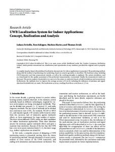
For the simulation to evaluate the performance of the noncoherent OOK UWB system with the noise power calibration, we consider AWGN channels. It is assumed that the pulse repetition interval is sufficiently large so that interference between pulses is avoided. We consider C time slots for the noise power calibration mode for every 10,000 data bits for an operation mode. Fig. 3 shows BER performance of the noncoherent OOK UWB system according to number C of the
Fig. 2. The operation mode and noise power calibration mode for the noncoherent OOK UWB receiver.
In the noise power calibration mode, current noise information estimated as the average value by summing noise power measured during temporary time slots, can
allocated time slots for the noise power calibration mode. Furthermore in this figure, performance curves of the conventional coherent system using the correlator, and the noncoherent systems based on power detection with the fixed and the ideal adaptive thresholds, also shown for comparison. We observe in the figure that
JOURNAL OF SEMICONDUCTOR TECHNOLOGY AND SCIENCE, VOL.4, NO.3, SEPTEMBER, 2004
performance of the ideal adaptive threshold is approximately 2 dB better than that of the fixed threshold. Simulation result also indicates that BER performance of the proposed scheme is favorably comparable to that of the ideal adaptive threshold, when number C of the allocated time slots for the noise power calibration mode increases. In addition, it is observed that performance is converged when the noise power calibration is performed beyond approximately 20 time slot duration. 10
B it E rro r R a te
10
10
10
10
-1
213
The impulse radio structure[6,7] is suitable to low power UWB communication systems. The block diagram of typical analog sub-system for the impulse radio-type noncoherent OOK UWB communication system is shown in Fig. 4. The sub-system consists of antenna, RF switch, RF stage, AFE and clock blocks[8]. The RF stage is composed of RF signal amplification, filtering and antenna driving block. The AFE consists of Sample-and-Hold (S/H), A/D (Analog-to-Digital) converter and impulse generator. Clock block is composed of local oscillator and delay time generator. The proposed design includes the AFE and delay time generator which produces clocks for the S/H block. 1. Impulse generator
-2
-3
Fixed-Th Adaptive-Th (Ideal) Correlator C=1 C=2 C=5 C = 10 C = 20 C = 50
-4
-5
4
6
8
10
12
14
16
Eb / No [dB]
Fig. 3. BER performance of the noncoherent OOK UWB system according to number C of the allocated time slots for the noise power calibration mode.
The UWB communication system based on impulse radio structure requires very narrow pulses whose width is typically below nanosecond. In the most previous work on impulse generation carried out in radar systems community, the impulses are generated using discrete devices and thus consume excessively large power. The proposed impulse generator is designed using state-of-art CMOS process and digital gates for high performance and low power consumption. The schematic of the proposed impulse generator is shown in Fig. 5. The proposed scheme generates impulses using the inverted signal and delayed signal from 100 MHz system clock. The NOR gate produces the final impulse from two signals.
III. ANALOG FRONT-END DESIGN FOR UWB SYSTEM Fig. 5. Schematic of the proposed impulse generator.
LNA & Filter
S/H
A/D Converter
CLOCK RF Switch
Local Oscillator
TX
Pulse Driver
Delay Time Generator
Impulse Generator
BASE|BAND
RX
Fig. 4. Block diagram of typical analog sub-system for the UWB communication system.
2. Analog Front-End for Receiver Blocks Sampling and parallelization of high speed RF signals is required for direct processing of received RF signals. The parallelization process reduces the operation speed, and the received signal is compared with the reference voltage for digital signal conversion. The conversion process for digital signal is done in the A/D converter and 1-bit resolution is enough in this application. The circuit similar to a sense amplifier in memory is used for the signal comparison and amplification, so simple and
214
SUCKCHEL YANG et al: A NONCOHERENT UWB COMMUNICATION SYSTEM FOR LOW POWER APPLICATIONS
appropriate 1-bit A/D converter is designed. Fig. 6 shows the block diagram and connections of the S/H blocks and 1-bit A/D converters. The schematics of the 1-bit A/D converter and positive edge triggered D-type flip-flop for synchronization are shown in Fig. 7. Delay time generator design using Phase Locked Loop (PLL) is desirable, however, inverter chain is used in this work because ring oscillator will be used in the PLL. Replacing inverter chain with the ring oscillator is easy, and the result using inverter chain is almost the same as the result using ring oscillator. The block diagram of delay time generator is shown in Fig. 8. Fig. 9. Simulation result of impulse generator.
Fig. 6. S/H circuit.
Fig. 7. 1-bit A/D converter and synchronizer.
The simulation result of impulse generator is shown in Fig. 9, while the simulation result of the delay time generator using inverter chain is shown in Fig. 10. The 1st, 2nd and last clocks are displayed. Ten clocks are generated from the delay generator and time spacing is about 1 nsec. Those clocks are used in the S/H blocks.
Fig. 10. Simulation result of delay time generator.
Fig. 8. Delay time generator.
3. Simulation Results The simulation is carried out using 0.m CMOS technology. The simulation is performed using SPICE and assisted by ADS in case of high speed RF signals.
Fig. 11. Simulation result of sample-and-hold block.
JOURNAL OF SEMICONDUCTOR TECHNOLOGY AND SCIENCE, VOL.4, NO.3, SEPTEMBER, 2004
The result of the S/H block and 1-bit A/D converter is shown in Fig. 11. The received pulse is compared to reference voltage and converter to binary values. The time resolution of AFE is very important in OOK UWB system because the maximum data rate and the accuracy of location are heavily dependent on it. However, the operation speed of AFE is limited by the process used, so the proposed AFE employs parallelization technique. One nsec resolution is achieved using 100 MHz system clock, thus higher resolution is possible by increasing the system clock or parallelization when the proposed architecture is adopted. The outputs of ten A/D converters show different values at fixed time, because the S/H control clocks for each A/D converter are delayed according to the system clock. The selected four signals show the different values. The parallelized outputs of A/D converters are not synchronized, so the D-type flip-flop is used for the purpose of synchronization.
215
based on power detection with noise power calibration for low power ubiquitous network applications. It was observed that the proposed UWB system can achieve good BER performance which is favorably comparable to that of the system using the ideal adaptive threshold, while maintaining simple receiver structure. In addition, low power AFE blocks for the proposed noncoherent UWB transceiver, were proposed and verified using CMOS technology. Impulse generator, delay time generator and 1-bit A/D converter with synchronizer were simulated and showed the feasibility of the proposed UWB AFE system.
ACKNOWLEDGEMENT This work was supported by the Soongsil University Research Fund.
REFERENCES
Fig. 12. The synchronized output of flip-flops.
The output of the flip-flop is shown in Fig. 12, and the plot shows that the signals are properly synchronized. The result shows that the proposed AFE is suitable for the noncoherent UWB system and its operation is verified with the output of impulse generator as the input signal. Connecting RF blocks will be required for more accurate verification.
IV. CONCLUSION In this paper, we proposed and verified the system architecture for the noncoherent OOK UWB system
[1] G. Borriello, “Key challenges in communication for ubiquitous computing,” IEEE Commun. Magazine, 5oth Anniversary Commemorative Issue, pp. 16-18, May 2002. [2] Federal Communications Commission, Revision of Part 15 of the Commission’s Rules Regarding Ultra-Wideband Transmission, ET Docket 98-153, April 2002. [3] http://www.ieee802.org/15/pub/TG3a.html [4] http://www.ieee802.org/15/pub/TG4a.html [5] I. Immoreev and A. Sudakov, “Ultra-wideband interference resistant system for secure radio communication with high data rate," Proc. IEEE Int'l Conf. Circuits & Syst. for Commun. (ICCSC 2002), pp. 230-233, St. Petersburg, Russia, June 2002. [6] M. Z. Win and R. A. Scholtz, “Impulse radio: How it works,” IEEE Commun. Lett., vol. 2, no. 2, pp. 36-38, February 1999. [7] I. D. O’Donnell, M. S. W. Chen, S. B. T. Wang, and R. W. Brodersen, “An integrated, low power, ultrawide band transceiver architecture for low-rate, indoor wireless systems,” Proc. IEEE Workshop Wireless Commun. & Networking, Pasadena, USA, September 2002.
216
SUCKCHEL YANG et al: A NONCOHERENT UWB COMMUNICATION SYSTEM FOR LOW POWER APPLICATIONS
[8] S. Y. Lee, Design and Analysis of Ultra-Wide Bandwidth Impulse Radio Receiver, PhD Dissertation, University of Southern California, August 2002.
Suckchel Yang received his B.S. and M.S. degrees in Electronic Engineering both from Soongsil University, Seoul, Korea in 2002 and 2004, respectively. He is pursuing Ph.D. degree at the same institution. His research area includes UWB and multi-carrier modulation. Jung-wan Park received his B.S. degree in Electronic Engineering from Soongsil University, Seoul, Korea. Since 2004, he has been working toward the M.S. degree in the same institution. His interests are mixed-signal IC and UWB communication system. Yong Moon received his B.S., M.S. and Ph.D. degrees all in Electronic Engineering from Seoul National University, Seoul, Korea in 1990, 1992, and 1997, respectively. From 1997 to 1999, he was a senior research engineer at LG Semicon, Inc. (currently Hynix). Since 1999, he has joined the School of Electronic Engineering Faculty at Soongsil University. His research interests are low power circuits, PLL and CMOS RF circuits. Won Cheol Lee received his B.S. degree in Electronic Engineering from Sogang University, Seoul, Korea in 1986, M.S. degree from Yonsei University, Seoul, Korea in 1988, and Ph.D. degree from Polytechnic University, New York in 1994, respectively. He joined Polytechnic University as a Post-Doctoral Fellow from July 1994 to July 1995. He has been an Associate Professor of School of Electronic Engineering, Soongsil University, Seoul, Korea since September
1995. He has been working in the HY-ITRC of Hanyang University on software defined radio as a researcher since July 2002. His research area includes wireless communication systems, UWB systems, MIMO space-time signal processing, and software defined radio. Yoan Shin received his B.S. (with Honor) and M.S. degrees in Electronic Engineering both from Seoul National University, Soul, Korea in 1987 and 1989, respectively, and Ph.D. degree in Electrical and Computer Engineering from The University of Texas at Austin in 1992. From 1989 to 1992, he was a recipient of Overseas Study Fellowship from Ministry of Education of Korean Government. From 1992 to 1994, he was with Microelectronics & Computer Technology Corp. (MCC) research consortium in Austin, Texas as a Member of Technical Staff. Since 1994, he has been with School of Electronic Engineering at Soongsil University, Seoul, Korea, and now is an Associate Professor. His research area includes multi-carrier modulation, UWB, and MIMO space-time signal processing.