Reconfigurable Control System, B Method, Modeling, UML, Code Generation. Abstract: ..... The operating of EnAS system, as explained in Fig- ure 3, is ...
A Novel R-UML-B Approach for Modeling and Code Generation of Reconfigurable Control Systems Raja Oueslati1,2 , Olfa Mosbahi1, Mohamed Khalgui3,1 and Samir Ben Ahmed2 1 LISI,
National Institute of Applied Sciences and Technology, INSAT, University of Carthage, Tunis, Tunisia 2 Faculty of Sciences, FST, University of Tunis El Manar, Tunis, Tunisia 3 Xidian University, Xi’an, China
Keywords:
Reconfigurable Control System, B Method, Modeling, UML, Code Generation.
Abstract:
This research paper deals with the modeling and code generation of Reconfigurable Control Systems (RCS) following UML and B methods. Reconfiguration means dynamic changes of the system behavior at run-time according to well-defined conditions to adapt it to its environment. A reconfiguration scenario is applied as a response to user requirements or any possible evolution in its environment. We affect a Reconfiguration Agent (RA) to RCS to apply an automatic reconfiguration. A new approach called (R-UML-B) is proposed. It consists of three complementary phases: UML specification, B specification and the simulation phase. The first phase models the RCS following UML class and state diagrams. The second phase translates UML specification into B specification according to the well-defined rules and R-UML-B formalism to define the Behavior, Control, Listener, Database and Executive modules of the RCS. Then, we determine the refinement model and the code generation of the B abstract model in C code. We verify the RCS by following the B method in order to guarantee the consistency and the correctness of the specification, refinement and code generation levels. The third phase imports the generated C code to implement a simulator, named B Simulator in order to test and validate the proposed approach. All the contributions of this work are applied to the benchmark production system EnAS.
1
INTRODUCTION
Control Systems (CS) are designed to perform functions in order to control a physical process in the real world such as automotive, avionics and industrial automation. These systems often have real-time computing constraints. Due to the trade-off between performance and rapid response to market changes and customer needs, the requirements in industrial CS are increasingly growing in terms of flexibility and agility (Theiss et al., 2009). In this context, one of the most promising directions to address these issues is the reconfiguration of CS. The reconfiguration consists in switching the system from its current configuration to another one at runtime by applying a reconfiguration scenario. We distinguish two types of reconfigurations: static (off-line) and dynamic (on-line) (Angelov et al., 2005). The former is applied off-line before system′ s cold start, whereas the latter is applied automatically at run-time. In the latter case, two types exist : manual reconfigurations to be executed by users and automatic (intelligent) reconfigurations
to be performed by intelligent agents that can be a physical resource (robot, machine ...) or a logical resource (scheduler), and hybrid reconfigurations which are the combination of manual and automatic reconfigurations. On the other hand, B is a formal software development method that covers software process from the abstract specification to the executable implementation. Moreover, it has been used successfully in major safety critical systems such as the automatic train operating system for METEOR, a driverless metro in the city of Paris (Behem et al., 1999), medical systems (M´ery and Singh, 2013) and electronic voting machines (Cansell et al., 2007). Also, a strong point of B is to have robust and useful tools to support the specification, design, proof, and code generation like Atelier B or B4free. In a previous work (Oueslati et al., 2014), we have proposed the new formalism called R-B to model RCS following the B method. The formalism R-B consists of two modules: Behavior and Control. The first module is the union of all system configurations
140 Oueslati, R., Mosbahi, O., Khalgui, M. and Ahmed, S. A Novel R-UML-B Approach for Modeling and Code Generation of Reconfigurable Control Systems. In Proceedings of the 11th International Conference on Evaluation of Novel Software Approaches to Software Engineering (ENASE 2016), pages 140-147 ISBN: 978-989-758-189-2 c 2016 by SCITEPRESS – Science and Technology Publications, Lda. All rights reserved Copyright
A Novel R-UML-B Approach for Modeling and Code Generation of Reconfigurable Control Systems
where each one is represented by a B machine Mi . The second module is formed by a set of reconfiguration functions handling automatic transformations between specific configurations in the behavior module after receiving reconfiguration requests to adapt the system to environment changes. When we applied a reconfiguration scenario, a reconfiguration function is executed to switch the system behavior from one configuration to another one at run-time, including the addition /removal of operations from a source Mi , to obtain a target M j machine. To avoid redundant calculations, we implemented a prototyped tool called Check R-B. This prototype can be added to B4free tool as a module to solve the redundancy problem of different behaviors sharing similar operations. The proposed solution allows us to implement automatically the code generation of the RA after the refinement of the B abstract machines. However, as a formal method, B cannot avoid inconsistencies and inaccuracies in specification. As cited in many research works (Meyer and Souqui`eres, 1999) (Nguyen, 1998), a combination of semi-formal and formal methods can contribute to a better specification of software engineering method. For this objective we propose to integrate the unified modelling language UML in the proposed development approach of RCS to borrow features from the two classes of specification, formal and semi-formal ones. Each method has been proved to be useful in the development of CS. Formal methods are based on mathematical notations and axiomatic which induce verification and validation. Furthermore, semi-formal methods are graphic, structural and user-friendly. Each method is applied on a suitable case study, that we regret some missing features we could find in the other class. This remark has motivated our work. We are interested in the integration of formal and semi-formal methods in order to lay out a specification approach which combines the advantages of theses two classes. To deal with the modeling and the code generation of dynamic reconfiguration of CS, we affect an RA to RCS to apply automatic reconfigurations. We offer in this work a new approach called R-UML-B method allowing the development of RCS from specification to code generation. We propose in this paper a development process which consists of three complementary phases in order to develop such systems: 1. UML specification, 2. B specification and 3. simulation phase. The first phase allows us to model the RCS following UML class and state diagrams. The second phase translates UML specification into B specification according to the well-defined rules and R-UMLB formalism to define the Behavior, Control, Listener, Database and Executive modules of the RCS. Then,
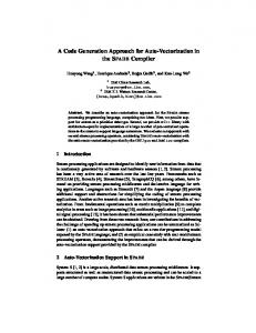
Requirements Specification Informal specification Abstract Model Specification Step
Abstract specification Refinement Proof Obligations Refinement
Refinement Model
Refinement Step Refinement 1 Refinement
Refinement Proof Obligations
Refinement n
Translation Code Generation Step
Refinement Proof Obligations
Code Generation Source Code (C, Ada)
Figure 1: B Method.
we determine the refinement model and the code generation of the B abstract model in C code. The third phase is for importing the generated code to develop a simulator with a suitable tool in order to validate our approach. The proposed approach is the first to our knowledge to deal with the modeling and the code generation of RCS following UML and B methods. The rest of the paper is organized as follows: in Section 2, we present the background in which we introduce B method, transformation rules from UML diagrams into B models and an overview about the implementation of RCS. In Section 3, we present the proposed approach R-UML-B to model and generate the code of RCS. In Section 4, we apply all contributions of this work to the case study EnAS. We finish by a conclusion and the exposition of our future works.
2
BACKGROUND KNOWLEDGE
In this section, we present an overview on well-known B method, transformation rules from UML to B specification and an overview about the implementation of RCS.
2.1 B Method We present in this subsection, the well-known B method. B is a formal method developed by Abrial (Abrial, 1996). It covers all the aspects in the software development of a system: Specification, Refinement and Code generation, as shown in Figure 1. It integrates set theory, logic predicate and generalized substitution language. The B method has a robust and useful tool Atelier B to support the specification, design, proof and code generation. 2.1.1 Specification Step The specification step consists in translating the software requirement into an abstract model in B. The B method is based on the notion of abstract machine 141
ENASE 2016 - 11th International Conference on Evaluation of Novel Software Approaches to Software Engineering
that is composed of three parts: (i) Header part describes by means of the clauses MACHINE and CONSTRAINTS, (i) Static part describes by means of the clauses SETS, CONSTANTS, PROPERTIES, VARIABLES and INVARIANT and (iii) Dynamic part describes by means of the clauses INITIALISATION and OPERATIONS. This model is finished when all the requirements are described in the model. 2.1.2 Refinement Step The following step consists in refining the abstract model of a software system into another mathematical model that is more concrete. This model is finished when all the components of the abstract model are refined into components that can be automatically translated into C code. 2.1.3 Code Generation Step The Atelier B tool translates automatically all the implementations of the concrete model into C code. 2.1.4 Composition in B Abstract machines can be combined, through the clauses INCLUDES and USES to build new specifications (Abrial, 1996). The clause INCLUDES allows a machine to be included in another one with read/write access. A machine M includes a machine M1 means that M has a full access to the constants, sets, variables and operations of M1 and operations of M can be defined by using any M1 operations. The clause USES allows a machine to be shared by another one with read only access. A machine M2 uses a machine M3, M2 can only make use of the static part of M3.
2.2 Transformation Rules from UML to B The authors in (Meyer and Souqui`eres, 1999) (Nguyen, 1998) have proposed the transformation rules from UML semi-formal specification to B formal specification. In what follows, we present the important ones. • From UML Class Diagram to B Specification: Each class is expressed by an abstract machine Classi that describes a deferred set CLASSi of the possible instances of the class Classi . The set of existing instances is modelled by a variable classi constrained to be a subset of CLASSi . For each attribute Attri , a variable attri is created and defined in the INVARIANT clause as a binary relation between the set classi and its associated type 142
Typeattr . The Assi j association between classes is formalised by adding a variable assi j and a property of invariance defining it as a binary relation between classi and class j . • From UML State Diagram to B Specification: For each diagram associated to the class Classi , we create an enumerated set STAT Ei which gathers all the states of the diagram. The state of an object is recorded by a variable statei defined as a function from the set classi of the existing instances of Classi to STAT Ei . Each event is formalized by an operation which is parameterized by the target objects and the eventual parameters of the event. Parameters are typed by a predicate in the precondition of the operation. The operation is defined by a SELECT substitution which has as many cases as transitions where the event appears. The operation modifies the state of the object and calls the operations associated to actions and events specified in the transition.
2.3 Implementation of Reconfigurable Systems Nowadays, important research works have been proposed to dvelop RCS. (Krichen et al., 2015) propose a model-driven engineering based approach to design reconfigurable distributed real-time embedded systems (DRES) with execution framework support. Their approach leads the designer to specify step by step the system from one abstract model to a concrete one. This target model is related to a specific platform leading to the generation of the most part of the system implementation. They also develop a new middleware that supports reconfigurable DRES. The work of (Gogniat et al., 2010) deals with the design of self-reconfigurable multiprocessor systems on chip. To provide a comprehensive approach, the authors address three major points : i) definition of an efficient architectural model with adapted API in order to help designer during the design steps, ii) a bitstreams repository hierarchy to face potential huge number of bitstreams which will be required for future versatile systems and iii) a complete design methodology starting from a high level of specification (UML). Increasing modeling abstraction levels allows to hide implementation details to the designer, leaving focus on system requirements rather than implementation issues. The contribution that we propose in the current paper is original since it addresses the modeling and the code generation of RCS following UML and B methods. To our knowledge, this is the first contribution addressing this problem.
A Novel R-UML-B Approach for Modeling and Code Generation of Reconfigurable Control Systems
UML Specification Class Diagram Behavior Module Database Module Control Module
Listener Module Executive Module
State Diagram Behavior Module Database Module Control Module
Listener Module Executive Module
1 B Specification Abstract Model
Transformation rules from UML to B R-UML-B Formalism
Refinement Model
Code Generation 2 Simulation Phase 3
B Simulator
C Code
2. B Specification: is composed of three steps as following: a. Abstract Model: using of the transformation rules defined previously and the R-UML-B formalism to obtain B abstract machines from UML diagrams, b. Refinement Model: refining the abstract model into another model more concrete, c. Generation Code: translating automatically all the implementations of the refinement model into C code using the Atelier B tool, 3. Simulation Phase: importation of the generated code to develop a simulator with a suitable tool called B Simulator.
Figure 2: R-UML-B Approach.
3.2 R-UML-B Formalism
3
R-UML-B APPROACH
In this section, we present the proposed R-UML-B approach for modeling and generation code of RCS. Then, we define the proposed UML-DR-B formalism.
3.1 Presentation of R-UML-B Approach To offer more flexibility to the execution of reconfiguration scenarios on RCS, we define an intelligent Reconfiguration Agent called RA which checks the environment′s evolution to adapt the system. The role of an RA is to apply an automatic reconfiguration on the CS. Our goal is to model and generate the intelligent RA code of an RCS. In this context, we define an R-UML-B approach to design an RA that defines a development process from models to code as shown in Figure 2. This process consists of three phases to be followed by the user: 1. UML Specification: modeling of the RCS following the UML class and state diagrams. It consists of five modules: Behavior, Control, Listener, Database and Executive. The behavior module defines all possible behaviors of the system. The control module is a set of reconfiguration functions applied to change the system from a behavioral configuration to another one at run-time when a reconfiguration scenario is applied as a response to user requirements or any possible evolution in its environment. The Listener module detects all events that trigger reconfiguration scenarios. The database module contains architecture, composition, data and comparative information of the RCS. The Executive module adds or removes the appropriate operations to respond to reconfiguration requests and to switch between the specific configurations at run-time,
In this subsection, we define the R-UML-B formalism to model RCS. It defines the behavior β, the control R, the Listener Listener, the Database Database and Executive Executive modules. Definition 1. R-UML-B. An R-UML-B formalism is a structure defined as follows: R-UML-B = (β, R, Listener, Database, Executive) where: (i) β is the behavior module, (ii) R is the control module, (iii) Listener is the listener module, (vi) Database is the database module and (v) Executive is the executive module of the RCS. Definition 2. Behavior Module. The Behavior Module β is the union of m configurations of the RCS. Each Behavior Module class of UML class diagram is expressed by an abstract machine presented as follows: β = {Mclass1 , Mclass2 , ..., Mclassi , ..., Mclassm }
Definition 3. Control Module. The Control Module R is a set of reconfiguration functions allowing automatic transformations between configurations. A reconfiguration function r(x,x′ ) is a structure changing the system from a configuration x to another one x’ defined as follows r(x,x′ ) = (Cond(x,x′ ) , S(x,x′ ) ), where: (i) Cond(x,x′ ) ∈{True, False}:the pre-condition of r(x,x′ ) , (ii) S(x,x′ ) :(• M) →(M• ) is the structure modification instruction where (• M) denotes the machine Mclassi before the application of r(x,x′ ) and (M• ) denotes the target machine Mclass j after the reconfiguration function r(x,x′ ) is applied. The structure S(x,x′ ) models the transformation from a Mclassi to another Mclass j machine when we apply a reconfiguration scenario. If Cond(x,x′ ) = True, r(x,x′ ) is executable, otherwise it cannot be executed. The structure modification instruction S(x,x′ ) guides the system transformation from (• M) to (M• ), including the addition /removal of operations from a source Mclassi , to obtain a target 143
ENASE 2016 - 11th International Conference on Evaluation of Novel Software Approaches to Software Engineering
Mclass j machine. The pre-condition of a reconfiguration function means specific external instructions and gusty functioning failures. Definition 4. Listener Module. The Listener Module called Listener is responsible for receiving the reconfiguration requests while the system is executing other functions. The occurrence of a request does not require the stopping of the system. This module is a set of external and internal events that trigger reconfiguration scenarios represented as follows: Listener = (Eventexternal , Eventinternal ) Where: Eventexternal depicts the user requests that occur to change the system production mode and Eventinternal represents the system errors. The Listener is modeled by UML class and translated into B machine MListener thanks to transformation rules from UML to B. Definition 5. Database Module. The Database Module called Database is a set of data having the following structure: Database=(Architecture, Composition, Data, Comparative) Where (i) Architecture represents the architectural reconfiguration level that defines the different system′ s architecture when particular conditions are met, (ii) Composition represents the composition reconfiguration level that changes the composition of operations for a given architecture, (iii) Data represents the data reconfiguration level that changes the values of variables without changing the system operations and (vi) Comparative compares configuration system before and after applying reconfiguration scenario to determine the processes to be used and their execution order. The Database Module is modeled by UML class diagram and translated into B machine MDatabase . Definition 6. Executive Module. The Executive Module called Executive is a set of operations of the behavior x and those of the behavior x’, represented as follows: Executive = (∪opiMclassi , ∪opiMclass j ) Where: ∪opiMclassi denotes the machine operations of Mclassi before the application of r(x,x′ ) and ∪opiMclass j denotes the target machine operations of Mclass j . The Executive adds /removes operations from a source Mclassi to obtain a target Mclass j machine. The Executive Module is modeled by UML class diagram and translated into B machine MExecutive . Definition 7. B Machine. A B machine Mi is the machine represented by the following tuple: Mi = (C, S, Const, P, V, I, Init, Op) Where: (i) C: the system constraints, (ii) S: the sets, (iii) Const: the constants, (iv) P: the properties constants , (v) V: the variables, (vi) I: the invariants, (vii) 144
Init: the initialization of variables and (viii) Op: the operations. All the components of the B machine are deducted from UML class and state diagrams according to the transformation rules from UML into B.
4
CASE STUDY: RECONFIGURATION OF INDUSTRIAL SYSTEM EnAS
In order to explain our contribution, we present in this section our demonstrator benchmark production system EnAS available at Martin Luther University in Germany. It is served for research and education purposes in many universities. Then, we apply our approach to the case study.
4.1 EnAS System EnAS transports workpieces from the benchmark production system FESTO into storing stations. The workpieces shall be placed inside tins to close with caps afterwards. The EnAS system is mainly composed of a belt, two jack stations (J1 and J2) and two gripper stations (G1 and G2). The Jack stations place new drilled workpieces from FESTO and close tins with caps, whereas the gripper stations remove charged tins from the belt into storing stations (ST1 and ST2). Initially, the belt moves a particular pallet containing a tin and a cap into the first jack station J1. Four production modes are assumed in this paper to be applied in EnAS, depending on the number of drilled workpieces nbpieces, tins and caps nb(tins+caps), as follows: • Policy1: If nbpieces/nb(tins+caps)