IEEE TRANSACTIONS ON MAGNETICS, VOL. 47, NO. 10, OCTOBER 2011
2943
A Parameterized Mesh Technique for Finite Element Magnetic Field Computation and Its Application to Optimal Designs of Electromagnetic Devices Shuangxia Niu, Yanpu Zhao, S. L. Ho, and W. N. Fu Department of Electrical Engineering,The Hong Kong Polytechnic University, Hung Hom, Kowloon, Hong Kong A parameterized mesh generation is presented for design optimization of electromagnetic devices. The proposed method requires no mesh regeneration, and hence the numerical simulation time can be reduced significantly. When the coordinates of nodes in the refined mesh are changed, the mesh topology will be kept, that is, the node connection relationship will remain the same as before. Thus the nodal solutions can be carried over from previous FEM results to subsequent FEM computation without the need of mapping the nodes between two meshes. Additionally, the mesh quality can remain high using a swapping diagonal technique. Based on the sample points obtained from FEM with parameterized mesh, the optimal model is reconstructed using the response surface methodology (RSM). The particle swarm optimization (PSO) method is then used to arrive at the optimal solution swiftly and efficiently. An optimal design of electromagnetic device is reported to verify the efficiency and effectiveness of the proposed method. Index Terms—Electromagnetic device, finite element, optimal design, parameterized mesh, PSO, RSM.
I. INTRODUCTION
T
O improve the performance of electromagnetic devices, geometrical size optimization is necessary in design processes. To a large extent, the success of optimal design depends on the accuracy of the mathematical model. Due to its high accuracy, finite element method (FEM) becomes an indispensable tool in the modeling of electromagnetic devices. During the optimization process, because of variation of geometrical sizes, the FEM mesh has to be generated repeatedly [1]. This remeshing process is time consuming and numerical noises often appear [2], [3]. In addition, the data transfer from the variables of previous meshes to the new meshes in FEM computations will give rise to inaccuracy. To guarantee the mesh quality during geometrical changes and to reduce numerical noise, mesh smoothing algorithm is often needed [4]–[7]. Laplacian smoothing emerges as one of the most popular methods [4]. Another related smoothing algorithm, namely, Winslow smoothing, is proposed to alleviate or guard against mesh folding in the process of mesh smoothing [5]. In the optimization process, it serves to adjust the position of interior nodes in the meshes by minimizing a particular mesh quality metric [6]. With suitable smoothing algorithm, the mesh quality is improved and the positions of the boundary nodes are kept unchanged. Since the increment of each point is small and each point is in the same material after the reconstruction of meshes, the results of the previous FEM solution serve as a good initial solution for subsequent FEM computation. However, at each optimization step, when the shapes of the device change, new meshes need to be obtained by solving time consuming Laplacian equation or weighted Laplacian equation. In this paper, a parameterized mesh generation method with a parameterized geometry model is proposed for finite element Manuscript received February 20, 2011; accepted April 11, 2011. Date of current version September 23, 2011. Corresponding author: S. Niu (e-mail:
[email protected]). Color versions of one or more of the figures in this paper are available online at http://ieeexplore.ieee.org. Digital Object Identifier 10.1109/TMAG.2011.2144574
analysis (FEA). This method starts from a geometry model with its dimensions depending on a set of geometrical parameters. From the geometry model, an initial mesh is created by using Delaunay algorithm, in which the coordinates of all the nodes are expressed as linear functions of its geometrical parameters. In the following mesh refinement, if a node is added at the barycenters of triangle elements or at the middle of edges, its coordinates are expressed as functions of the geometrical parameters. Afterwards, in the optimal design process, all the coordinates of the nodes will vary accordingly as the geometrical sizes change. Based on the sample points obtained from FEA with parameterized mesh, the relationship between the objective function and geometrical parameters is reconstructed using the response surface methodology (RSM). The use of RSM often saves computational time in the optimization process without losing accuracy in the evaluation of the objective function. The particle swarm optimization (PSO) method is used to find the optimal solution swiftly and efficiently. Compared with existing shape optimal design methods, the proposed method has its salient merits. Firstly, the mesh regeneration procedure is avoided in the optimization process, hence the computing time and numerical errors are greatly reduced. Secondly, even the positions of the nodes in the refined mesh are changed, each individual node will be kept and the solutions on the nodes can be carried over from the previous FEM results to the following FEM computation, hence no mapping of nodes is needed. Thirdly, the mesh quality can remain high using a swapping diagonal technique. Finally, with the proposed parameterized mesh being incorporated with the RSM and PSO, the computation time is reduced while the computation accuracy is guaranteed. The validity of this proposed method is verified through an optimization study of a magnetic device as reported below. II. PROPOSED METHOD A. Parameterized Mesh Technology To find the solution of electromagnetic fields using FEM, the first step is, inevitably, to input the geometric data of the field
0018-9464/$26.00 © 2011 IEEE
2944
IEEE TRANSACTIONS ON MAGNETICS, VOL. 47, NO. 10, OCTOBER 2011
domain into the computer programs. Supposing there are geometry parameters , which will vary during the optimization process, they can be expressed as
(1)
.. .
(4)
A two dimensional (2-D) FEM with triangular element is used as an illustrating example to show the basic idea. The coordinates of the node in a finite element mesh can be expressed as linear functions of the parameters
.. . (5) (2)
.. . (3) where and are the matrices with constant coefficients. For each node, not only the current coordinate values associated with current parameter column matrix are stored, these two matrixes and will also be stored. When changes, according to (2) and (3), the coordinates of all nodes will change accordingly. After inputting the initial coarse mesh with and for each vertex, the initial coarse mesh will be refined successively to generate a high-quality computational mesh for the optimization analysis. The following steps are implemented to derive the desired mesh for FEA: i) A set of uniformly distributed nodes in the - plane is added to the initial mesh and the swapping diagonal operations are done using the Delaunay method [8]. This mesh adaptation operation is done only once and the aim is to improve the aspect ratio of the initial mesh. Then the following steps are executed repeatedly until the desired mesh is obtained. ii) To make the resultant mesh as uniform as possible, those elements with areas greater than the mean area of all the elements in the mesh are marked and refined by adding the barycenter to these elements. iii) The domain boundaries and material interfaces are refined by the method of bisection of the longest edge at which diagonal swapping operations are not allowed [9]. iv) All of the elements are marked with a quality factor, which is an indicator of the shape goodness of the triangular element [3]. Those with bad quality factor will be refined using the bisection method too. During mesh refinement, if a new node needs to be inserted at the barycenter of the triangular element with three nodes , its coordinates are expressed as
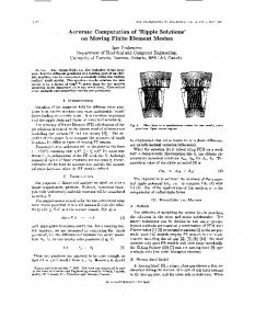
That is to say, if a node is added at the barycenter of the triangle, its coefficients under the parameters are . If a node is added at a general position within the triangle, the new coefficients are expressed as , where the weights are the ratio of the sub-triangular areas divided by vertex to the whole triangular area with the vertexes . During optimal design process, when the parameters vary based on the optimal scheme, all coordinates of the original nodes and the added nodes in the refined mesh are changed automatically. A simple example illustrating this parameterized mesh method is given in Figs. 1 and 2. It is noted that the coordinates of all the nodes will also change when the parameters change. B. Response Surface Methodology Response surface methodology (RSM) is an interpolation technique that fits a multidimensional function to its function values at some sample points on an arbitrary function domain [10]. A brief introduction of RSM is given below. Let be the set of non-negative real numbers and suppose a scalar function be continuous with . A radial basis function on is defined in the form (6) is the Euclidean norm. where In general, the reconstruction of an objective or constraint function on the basis of its value at a given set of sample points under some radial basis functions is (7) The coefficients linear algebraic equation:
are determined by the following (8)
NIU et al.: A PARAMETERIZED MESH TECHNIQUE FOR FINITE ELEMENT MAGNETIC FIELD COMPUTATION
2945
Fig. 3. The geometry and its parameters. Fig. 1. Parameterized mesh results when the parameters are mm. (a) Initial mesh. (b) Refined mesh.
mm,
Fig. 4. Results of the initial mesh when the parameters are mm, mm. (a) Mesh. (b) Flux lines. Fig. 2. Results with geometry shape changes. (a) mm. (b) mm, mm.
mm,
where
is the interpolation matrix and . In this paper, the globally supported radial basis function is taken as (9) with . At the sample points, FEM is used to accurately evaluate the objective function. Parameterized mesh technology is adopted to improve the efficiency of FEM as the geometrical sizes change. Since no mesh regeneration is needed, the numerical computation time is greatly reduced. By using RSM, the objective function can be reconstructed without losing the computation accuracy and which can be directly optimized using PSO method. C. PSO Algorithm PSO is a population based stochastic searching and optimization algorithm [11]. In PSO, a potential solution is named as a particle. The trajectory of each particle is gracefully adjusted towards its own best position and the global best position discovered by its neighbors as well as by the whole swarm. The algorithm is expressed as
(10) (11) where is the inertial weight to adjust the global and local optimization capability of the method; and are the acceleration coefficients; and are two uniform random functions;
mm,
and are, respectively, the velocity and position; represents the best particle position among the entire population and is the previous best particle position. Since the PSO method has the capability in searching the global optimum with high probability and its convergence rate is fast, it is advantageous to be combined with RSM in FEM to determine the optimized geometrical sizes of electromagnetic devices. III. EXAMPLES The proposed method is utilized to optimize the geometrical sizes of an electromechanical levitation device, aiming to obtain a maximum magnetic force per unit volume of permanent magnet (PM). The PM volume constraint condition is that the volume of PM is equal to 10 m and the airgap length is 50 mm. The materials, geometry and design parameters are shown in Fig. 3. There are three geometry variables, namely, , and . The geometry constraints are listed below: mm mm, mm mm, mm mm. The initial mesh and the magnetic flux line distribution are shown in Fig. 4. After mesh refinement, the mesh result and flux lines are shown in Fig. 5. The number of elements is 83309; the CPU time for mesh generation is 9.4 seconds and the CPU time for the FEA equation solving is 88.2 seconds. It can be seen that the mesh generation is time consuming. The optimized geometry is shown in Fig. 6. When the geometrical dimensions change during the optimization process, even the position of the nodes in the refined mesh are changed accordingly, its mesh quality will remain high as shown in Fig. 6. Fig. 7 shows the slice contours of the force versus geometrical parameters . Two hundred eighty sample points are computed using FEM, and approximation of the magnetic force as a function of the geometry parameters is reconstructed by the
2946
IEEE TRANSACTIONS ON MAGNETICS, VOL. 47, NO. 10, OCTOBER 2011
Fig. 5. Results of refined mesh. (a) Mesh. (b) Flux lines.
Fig. 8. Results of convergence in PSO.
merical computation time significantly. This method requires no mapping of nodes. When the positions of the nodes in the refined mesh are changed, each individual node will be kept and the solutions on the nodes can be carried over from the previous FEM results to the following FEM computation. Based on the finite sample points obtained from the FEM with the parameterized mesh method, the original problem is reconstructed using the RSM. The PSO method is used to calculate the objective function swiftly and efficiently. An example of geometry optimization has been given to verify the efficiency and effectiveness of the proposed method.
Fig. 6. Optimal results of geometry sizes. (a) Mesh. (b) Flux lines.
ACKNOWLEDGMENT This work was supported by the Research Grant Council of the Hong Kong SAR Government under projects PolyU 5176/ 09E, 5184/09E and G-YX4B. REFERENCES
Fig. 7. Magnetic force
versus geometry parameters
.
response surface method with multi-quadratics basis function. The PSO algorithm is adopted to search for the optimal solution of the scalar continuous function in the solution space . The population size of all the particles is set to be 40, the maximum iteration number is taken to be 200 and the radial basis function is taken to be in the reconstruction process. The convergence history profile of the best fitness value up to current iteration is given in Fig. 8, where the optimal solution is [2.75 mm, 7.63 mm, 39.75 mm], and the corresponding objective function value is 1.26 N. IV. CONCLUSION A parameterized mesh generation method is proposed for the optimal design study of electromagnetic devices. The method does not need repetitive mesh regenerations. Since the mesh generation is time consuming, this method can reduce the nu-
[1] K. Yamazaki, H. Ishigami, and A. Abe, “An adaptive finite element method for minor shape modification in optimization algorithms,” IEEE Trans. Magn., vol. 44, no. 6, pp. 1202–1205, 2008. [2] S. L. Ho, W. N. Fu, and H. C. Wong, “Generation and rotation of 3-D finite element mesh for skewed rotor induction motors using extrusion technique,” IEEE Trans. Magn., vol. 35, no. 3, pp. 1266–1269, 1999. [3] S. L. Ho and W. N. Fu, “A fully automatic mesh generation method for the movement field modelling,” in 2nd Chinese Int. Conf. Electrical Machines, Hangzhou, China, 1995, pp. 624–630. [4] P. Knupp and S. Steinberg, The Fundamentals of Grid Generation. Boca Raton, FL: CRC Press, 1993. [5] A. Winslow, “Numerical solution of the quasilinear poisson equations in a nonuniform triangle mesh,” J. Comp. Phys., vol. 135, no. 2, pp. 149–172, 1967. [6] S. Shontz and S. Vavasis, “A mesh warping algorithm based on weighted Laplacian smoothing,” in Proc. 12th Int. Meshing Roundtable, 2003, pp. 147–158. [7] K. Yamazaki, H. Ishigami, and A. Abe, “An adaptive finite element method for minor shape modification in optimization algorithms,” IEEE Trans. Magn., vol. 44, no. 6, pp. 1102–1205, 2008. [8] S. W. Sloan, “A fast algorithm for constructing Delaunay triangulations in the plane,” Advances in Engineering Software, vol. 9, no. 1, pp. 34–55, 1987. [9] J. Penman and M. D. Grieve, “Self-adaptive mesh generation technique for the finite-element method,” IEE Proc., vol. 134, no. 8, pt. A, pp. 634–650, 1987. [10] S. L. Ho, Y. S. Yang, G. Z. Ni, and H. C. Wong, “A response surface methodology based on improved compactly supported radial basis function and its application to rapid optimizations of electromagnetic devices,” IEEE Trans. Magn., vol. 41, no. 6, pp. 2111–2117, 2005. [11] M. Clerc and J. Kennedy, “The particle swarm—Explosion, stability, and convergence in a multidimensional complex space,” IEEE Trans. Evol. Comput., vol. 6, no. 1, pp. 58–73, 2002.