20th International Conference on Composite Materials Copenhagen, 19-24th July 2015
A PARAMETERIZED SURFACE METHOD TO DETERMINE OPTIMAL VARIABLE STIFFNESS LAYUP DESIGN BY GLOBAL SEARCH S.H. Hesse*,1,2, A. Arsenyeva2 , D.H.-J.A. Lukaszewicz1, F. Duddeck2 *Corresponding Author, Email:
[email protected] BMW Group, Research and Innovation Centre, Knorrstraße 147, D-80788 Munich, Germany 2 Chair of Computational Mechanics, Technische Universität München (TUM) Arcisstr. 21, 80333, Munich, Germany
1
Keywords: Fibre steered laminate, Optimisation, variable stiffness laminates, Iso-contour method, manufacturing constraints. ABSTRACT We propose a method related to the level-set method to find optimal steered fibre or variable stiffness (VS) designs for composite laminates. In order to steer the fibres, iso-contour lines of an artificial surface, defined over a 2D geometry domain, are used. The artificial surface is based on a spline approach using a relatively small number of control points. This ensures the smoothness of the artificial surface which can help guarantee continuity/smoothness of the obtained fibre paths. The tangents of the iso-contours of this surface are projected on a structure mesh as fibre angles and the desired structural response is computed; in our case the critical buckling load or a point displacement. To ensure certain manufactural properties of the fibre angle design, the average fibre curvature is constrained. Because of the relatively small number of control points we can use global optimisers; such as evolutionary algorithms, or swarm based options, e.g. Ant Colony optimisation. Results of two example problems show an improved performance with a constraint on average curvature. Future possibilities are discussed. 1
INTRODUCTION
Steered fibre or Variable Stiffness (VS) laminates may show a significant performance improvement over optimised Constant Stiffness (CS) laminates [1, 2]. Due to recent advances in Automated Fibre Placement (AFP) machines [3], the topic of VS laminates has been well researched [1, 2, 4, 5, 6, 7]. Examples of performance improvements include maximizing the critical buckling load, minimizing compliance and maximizing strength. There are different approaches in finding the optimal VS design. Abdallah, IJsselmuiden and Peeters [1, 2] use a three step approach where firstly the stiffness distribution is optimised using Lamination Parameters (LP), secondly the local stacking sequences are optimised to fit the optimal LPs and thirdly optimal fibre paths are searched to fit the optimal fibre angle distribution. They use gradient based optimisation algorithms in a Conservative Convex Separable Approximation (CCSA) framework with analytically derived sensitivities. This leads to computational efficiency and quick convergence, but is limited to local search optimisation. Honda [4] describes fibre angle distributions using the contour lines of cubic polynomial functions. He integrates manufacturability by deriving the average curvature, similar to Peeters. By implementing a multi-objective optimisation using the Non-dominate Sorting Genetic Algorithm II (NSGA-II) he is able to compare strength versus manufacturability in the resulting Pareto front. Van Campen et al. [5] uses a GA in an optimisation framework to translate an optimised LP distribution into a manufactural layup design considering the curvature as a measure for manufacturability. He has a two stage approach; local and global. Firstly local points in LP space are converted into a realistic stacking sequence in terms of fibre angles. Secondly a Cellular Automaton (CA) framework is used to globally converge to a manufactural design. Wu et al. [6] used a Genetic Algorithm (GA) to solve a non-convex optimisation problem. They introduced a new non-linear mathematical description based on Lagrange Polynomials to represent the
20th International Conference on Composite Materials Copenhagen, 19-24th July 2015
distribution of fibre angles. The GA was used to compute the optimal non-linear fibre angle distribution of layups with two design plies for maximum buckling load for simply supported and free edged boundary conditions. Results where shown for three problem definitions, with 6, 18 and 25 design variables respectively. Their results showed good correlation with the work by IJsselmuiden et al. [8] who optimised the same buckling problem, but using gradient based algorithms. However, no curvature constraint was implemented in this work by Wu et al. A noticeable difference between the different methods is the choice between either a gradient [1, 2] or stochastic (often Genetic Algorithm (GA)) based [4, 5, 6] algorithm for optimisation, here also named as global search algorithm. It is generally understood that gradient based optimisation provides good optima at high computational efficiency, given the gradients can be derived analytically [2]. However, this type of optimisation provides only local optima and requires therefore good initial designs. The stochastic based optimisation algorithms, such as Genetic Algorithms (GA) have the advantage of global search, but also have non-consistent results due to the stochastic nature of the methods and generally require much iteration at subsequent computational costs. This leads to long run times and low computational efficiency when compared to gradient based methods. A logic consequence is to use the global search approach to scan the entire design domain for promising designs and use these as initial designs in a gradient approach. Most of the AFP machines impose manufacturing constraints on VS laminate designs [3]. Such a machine constructs a laminate by laying (pre-impregnated) fibre tows along a predefined path. When the curvature imposed on a tow becomes too severe, the compressed side of the tow will show local failure, such as wrinkling and buckling. This reduces the mechanical performance of the VS laminate and should therefore be avoided. This manufacturing constraint poses one of the biggest challenges in steered fibre laminate designs. In the research presented above this manufacturing constraint is often represented by a maximum on the average or local curvature. Gradient based optimisation can easily integrate both average and local curvature constraints. Global search methods are usually not suited for the large number of design variables associated with VS designs. Integrating curvature constraints increases the problem difficulty further by complicating the design space and are therefore not incorporated directly into the global search algorithm. When designing fibre paths, other manufacturing constraints should be considered. Some of these are the thickness change due to fibre path curvature changes over the panel, local tow overlap and tow gaps [1]. These challenges are not easily solved and remain an interesting topic for further research, but are not included in this paper. Further research is needed to improve the global search methods for VS laminate designs with integrated manufacturing constraints. We propose a method, based on earlier work by [7], related to the level-set method [9]: in order to steer the fibres, iso-contour lines of an artificial surface, defined over a 2D geometry domain, are used. The artificial surface is based on a spline approach [10] using a relatively small number of control points. This ensures the smoothness of the artificial surface which can help guarantee continuity/smoothness of the obtained fibre paths. The tangents of the iso-contours of this surface are projected on a structure mesh as fibre angles and the desired structural response is computed; in our case the critical buckling load and a point displacement. To ensure certain manufactural properties of the fibre angle design, the average fibre curvature is constrained. Because of the relatively small number of control points the use of global optimisers is feasible; such as evolutionary algorithms, or swarm based options, such as Ant Colony optimisation. In this paper a combination of constrained evolutionary and simplex algorithms is used. 2 ISO-CONTOUR METHOD In this paragraph, the method of the 2D fibre steering optimisation is described. The key idea of the method is to use an artificial surface, which is defined over the 2D domain, in order to control fibre paths [7]. The method will be described in detail for 2D geometry, a scheme of the method is presented
20th International Conference on Composite Materials Copenhagen, 19-24th July 2015
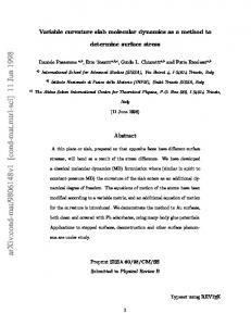
in Figure 1.
Figure 1: The workflow of the iso-contour based method. First of all, a box domain, containing the geometry domain should be defined, and Cartesian coordinates are defined over this rectangular box. Overlaid control points are then defined in this 2D box, e.g. based on the mesh, where the number and locations of the points can be varied. To control the artificial surface, a “height” is assigned to each of these control points and a surface is fitted over all control points, interpolating the heights. In the current work, non-parametric spline surfaces are used. Similar to a geodesic map, the iso-contour lines can be obtained from this artificial interpolating surface. These iso-contours guide the fibre paths at each point of the 2D geometry domain, with the fibre direction aligned to the iso-contour line. Finally, the “heights” defined in the control points are the design variables, which means, that the number of control points represents the dimension of the optimisation problem. In the first stage the simple evolutionary algorithm with constraint handling from DAKOTA [11] is used for global search of the potentially good designs. Next, by using the constrained simplex search (COBYLA method) from DAKOTA [11] the quality of the solution is refined. It is assumed that homogenized properties of the fibre reinforced composite (e.g. laminates) are already known and fit into the orthotropic material model. In this case, the main principal axis of this orthotropic material is aligned with the fibre direction. Changing of the fibre direction of the composite is then equal to rotating the material’s principal axes. 3 CURVATURE CONSTRAINT The average curvature is calculated as the rate of change in fibre angles in the design domain. The curvature, 𝜅, can therefore be expressed as the norm of the divergence of the fibre angle, 𝜃:
𝜅 = ‖∇𝜃‖
(1)
Using a curvature operator 𝑲 the average curvature can be expressed as: 1 (2) 𝜅 2 = 𝜽𝑡 ⋅ 𝑲 ⋅ 𝜽 2 where 𝜽 is the vector containing the nodal fibre angles. The curvature operator or matrix 𝑲 is similar to a Laplacian operator. The 𝑲 matrix describes the relative differences in fibre angle orientations and is defined as follows: 2 (3) 𝑲= 𝑳 Ω where 𝑳 is the actual Laplacian operator and Ω is the total area. The Laplacian operator 𝑳 is constructed by assembling the 3x3 element Laplacian matrices 𝑳𝑒 , which are defined as:
20th International Conference on Composite Materials Copenhagen, 19-24th July 2015
1 ⋅𝒍 𝒍 4Ω𝑒 𝑖 𝑗 1 𝒍1 ⋅ 𝒍1 𝑳𝑒 = [ ⋮ 4Ω𝑒 𝒍 ⋅ 𝒍
𝑳𝑒 =
3
1
𝑖, 𝑗 = 1,2,3 ⋯ 𝒍1 ⋅ 𝒍3 ⋱ ⋮ ] ⋯ 𝒍3 ⋅ 𝒍3
(4)
where Ω𝑒 equals the triangular element area, 𝒍 equals the element side vectors and the subscripts 𝑖 and 𝑗 are the element side numbers, for clarification see Figure 2. It should be noted that in this research quadrilateral elements are used. The triangular element Laplacian, 𝑳𝑒 , as derived in equation (4), can still be used by discretising all quadrilateral elements as two triangular elements.
Figure 2: nomenclature of a triangular element. With the average curvature 𝜅 we can now establish a curvature constraint as follows: 1 𝑔 = 𝜽𝑡 ⋅ 𝑲 ⋅ 𝜽 − 𝜅02 ≤ 0 2 where 𝜅0 equals the minimum allowed curvature.
(5)
The average curvature is relative easy to implement and because only a single constraint formulation is required it is also computationally efficient. The downside is the average nature of the constraint definition; locally there is still the possibility of large curvatures. In this research this effect is considered negligible, because the purpose of the proposed method is to provide good initial designs for later optimisation by gradient based methods. As Peeters et al. [2] showed, gradient methods can easily be combined with local curvature constraints which may iron out the possible local artefacts resulting from our proposed method. 4 EXAMPLE PROBLEMS To demonstrate the performance of the method, two simple 2D examples are regarded. The method was implemented as a python class combined with ANSYS. For modelling the artificial surface, the spline interpolation function from the SciPy library in python [12] is used. ANSYS software is used for performing Finite Element (FE) simulations and DAKOTA software is used for the optimisation. For the FE analysis first order shell elements (SHELL181) are taken. This type of element can be used for the modelling of layered composite shells. The following lamina material properties are used for the example problems: The Young's moduli are equal to: 𝐸1 = 130 GPa, 𝐸2 = 10 GPa, shear modulus 𝐺12 = 5 GPa and Poisson's ratio equals 𝜈12 = 0.35. 4.1 Two loads carrying plate example The simply supported plate with a top loading (as shown in Figure 3) is the first example. The dimensions of the plate are taken as 16 m x 10 m, thickness of each layer equals 1 mm. The number of design variables is equal to 9 (3×3 control points, red points in Figure 3 (left)). The objective of the
20th International Conference on Composite Materials Copenhagen, 19-24th July 2015
optimisation is to minimize the average displacement on the top line. The optimisation is run unconstrained as well as with with 2 different average curvature constraints. The results are compared with a reference CS laminate. In this example only one layer laminates are used, meaning only a single design layer needs to be optimised. For comparison, the load paths for an equally loaded isotropic design are shown in Figure 3 (right).
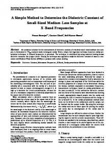
Figure 3: The supported plate with a top loading test problem with overlaid control points (left) and load paths for panel with isotropic material (right). Figure 4 shows the optimal artificial 3D surface configuration with corresponding iso-contours from which the corresponding fibre orientations are obtained and applied onto the FE model. Visual comparison of the optimal iso-contours and the load paths in Figure 3 show, that the obtained optimal iso-lines approximately follow the load paths, resulting in the stiffer structure. This result shows the tendency of the proposed method to place the local fibre direction in the direction of the load path.
Figure 4: Optimal spline surface (left), iso-contours for optimal spline surface (middle) and corresponding fibre angle at each element (right). Figure 5 shows the results obtained for different average curvature constraints. As can be seen, obtained solutions are still very close to the unconstrained optimal fibre alignment, although now the iso-lines are significantly less curved.
Figure 5: Iso-lines obtained with maximum average curvature constraint of 0.4 (left) and 0.2 (right) Table 1 shows the comparison of the displacement on the top edge of the plate for the optimal results with and without curvature constraints.
20th International Conference on Composite Materials Copenhagen, 19-24th July 2015
Curvature constraint [m-1] Without constr. 0.4 0.2
Displacement on the top line, [m] 3.064e-5 3.416e-5 3.68e-5
Table 1: Comparison of the results for models with and without curvature constraints. Table 2 shows the normalized optimised critical displacement results, 𝛿̃𝑐𝑟 , for the reference laminate and for the optimised VS laminates for different constraint values. The critical displacements are normalized with respect to the critical displacement of an optimised CS laminate. The optimised CS laminate has a 90° ply orientation. It can be concluded that the optimised VS designs perform significantly better than the optimised constant stiffness (CS) laminate. 𝜅0 [m ] 𝛿̃𝑐𝑟 -1
90° ply 1.0
∞ 2.027
Variable Stiffness 0.4 1.818
0.2 1.688
Table 2: Comparison of the minimal displacement after optimisation for the VS laminates and the 90° reference laminate.
4.2 Uni-axial buckling of the cylindrical plate with a hole The second example is taken from [2]: a cylindrical plate with a hole which is simply supported on the straight edges and subjected to uni-axial compression at the curved edges, as shown in Figure 6. This example is designed as a simplified fuselage section with a window. The sides are 0.5 m x 0.5 m, radius of the curvature is 0.75 m, the radius of the hole is 0.12 m. The ply thickness equals 1 mm. The material from the first example is used here as well. The aim of this test problem is to compare the optimal VS design obtained using the proposed method with a CS reference design. A four ply balanced and symmetric laminate is optimised, using a single design layer. For each element in the FE model the full laminate can be defined as [±𝛼]𝑠 , where 𝛼 is the local fibre angle in the design layer. There are nine control points distributed as 3 x 3 over the panel, resulting in nine design variables for the design layer. The plate is optimised for maximum critical buckling load, subject to an average curvature constraint.
Figure 6: The cylindrical plate with a hole in buckling test problem (note: shown mesh is not used!). Figure 7 shows the FE mesh used for this problem (right) and the optimal iso-contour for the unconstraint problem. It is clear that the tendency of the fibre is to be straight near the edges, providing stiffness in the compression direction on the straight edges, and have a more 45° degree oriented direction around the hole (on the diagonals), limiting out-of-plane deformation of the panel. Indeed, intuitively this is close to the optimal results for the posed buckling problem.
20th International Conference on Composite Materials Copenhagen, 19-24th July 2015
Figure 7: Optimal iso-contours for unconstraint problem (left), mesh used in this example (right).
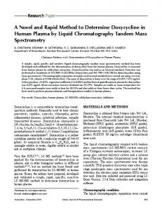
Figure 8 shows the optimal iso-contours for each design layer corresponding to three different curvature constraints. The iso-contours presented in Figure 8 clearly show the tendency of the fibre to be straight near the straight edges and at 45° near the middle. Again, intuitively this is optimal for the presented buckling problem.
Curvature Constraint 𝜅0 = 5
Curvature Constraint 𝜅0 = 4
Curvature Constraint 𝜅0 = 2
Figure 8: Comparison of optimal iso-lines in the design ply for 4-ply laminated plate obtained with different manufacturing constraints (Hole is not shown). In Table 3 the normalized critical buckling loads, 𝑃̃𝑐𝑟 , for the reference laminate and for the optimised VS laminates are presented. The critical buckling loads are normalized with respect to the critical buckling load of a four layer balanced and symmetric laminate consisting of 45° plies: [±45°]𝑠 . It can be concluded that the optimised VS designs perform significantly better than the constant stiffness (CS), [±45°]𝑠 , laminate. We also optimised for a CS laminate design, resulting in a [±92°]𝑠 laminate, the result is also presented in Table 3. When the optimised VS laminates are compared to the optimal CS result, the improvement is less significant. However, even for low curvature, the optimised VS laminate is still an improvement over the optimised CS design. These results show the capability of the proposed method to find significantly better designs, even with small curvature constraints, while using only a limited number of design variables.
𝜅0 [m ] 𝑃̃𝑐𝑟 -1
[±45°]𝑠 1.0
[±92°]𝑠 1.387
∞ 1.917
Variable Stiffness 5 4 1.517 1.478
Table 3: Comparison of the critical buckling load optimisation results.
2 1.453
20th International Conference on Composite Materials Copenhagen, 19-24th July 2015
5
DISCUSSION AND FUTURE RESEARCH
In this paper only one design layer was used for the optimisation of VS laminates. To provide more realistic results and acquire possible better optima, more design layers should be used. The proposed method is able to optimise multiple design layers by simply created multiple parameterized surfaces. More research is needed here however. Of interest is the influence of the increase in design variables on the optimisation performance. This research did not present any optimisation history, convergence rate or anything related to the efficiency of the optimisation algorithm. This was done on purpose as only the standard available optimisation algorithms from the DAKOTA were used and no attention was paid to the actual optimisation performance. The focus of this paper is the validity of the proposed method and therefore any available global search algorithm with constraint handling can be used. First steps were made to improve on the optimisation algorithm. Therefore the proposed method was also optimised using an adapted Ant Colony Optimisation algorithm for continuous domains (ACOR) [13], where a constraint handling algorithm was introduced. The first results using ACOR as the optimisation algorithm for the proposed method look promising compared to the optimisation method described in this paper. The final research and results will be published in a future paper. 6
CONCLUSION
A novel method was presented that used iso-contours, derived from spline based surfaces, to represent fibre angles in fibre steered composite laminate plies. Using a set of control points distributed over the design space, the local height of the surface can be controlled. The iso-contours from this surface were projected on a structural mesh, where the tangents of these contours were taken as the element central fibre angles. A simple evolutionary algorithm was used as global optimiser, using the relatively small number of control points as design variables. Local refinement was done by a simplex based algorithm. Manufacturability was integrated by using a maximum average curvature as an optimisation constraint. As validation of the proposed method two example problems were solved. Results showed a significant improvement in the performance over constant stiffness (CS) designs. In the first example, maximizing stiffness showed an improvement of 103% over its optimised CS counterpart, without constraints. With an average curvature of 0.2 m-1, still an improvement of 69% is achieved. For the second example, an improvement of 34% is achieved over the optimised CS laminate design when unconstrained. With an average curvature constraint of 5 m-1, an improvement of 6.4% is achieved. It can be concluded that presented method is able to find good optima. This means the method shows promise as an initial design finder for gradient based algorithms. It should be noted however that these examples did not prove the global search performance of the proposed method and further research is needed. However, global search performance is mainly dependant on the choice of optimisation algorithm.
ACKNOWLEDGEMENTS The authors would like to thank the Aerospace Multidisciplinary Enabling Design Optimisation project (AMEDEO), Marie Curie Actions - Research Fellowship Programme, Seventh Framework Programme (FP7). The authors would also like to express their gratitude to BMW Group to carry out and publish this research.
20th International Conference on Composite Materials Copenhagen, 19-24th July 2015
REFERENCES
[1] S. IJsselmuiden, Optimal Design of Variable Stiffness Composite Structures Using Lamination Parameters, Technische Universiteit Delft, 2011. [2] D. M. Peeters, S. Hesse and M. M. Abdalla, "Stacking sequence optimisation of variable stiffness laminates with manufacturing constraints," Composite Structures, vol. 125, no. 0, pp. 596-604, 2015. [3] D. H.-J. Lukaszewicz, C. Ward and K. D. Potter, "The engineering aspects of automated prepreg layup: History, present and future," Composites Part B: Engineering , vol. 43, no. 3, pp. 997-1009, 2012. [4] S. Honda, T. Igarashi and Y. Narita, "Multi-objective optimization of curvilinear fiber shapes for laminated composite plates by using NSGA-II," Composites Part B: Engineering, vol. 45, no. 1, pp. 1071-1078, feb 2013. [5] J. M. J. F. Van Campen, C. Kassapoglou and Z. Gurdal, "Generating realistic laminate fiber angle distributions for optimal variable stiffness laminates," Composites Part B: Engineering, vol. 43, no. 2, pp. 354-360, mar 2012. [6] Z. Wu, P. M. Weaver, G. Raju and B. C. Kim, "Buckling analysis and optimisation of variable angle tow composite plates," Thin-Walled Structures , vol. 60, no. 0, pp. 163172, 2012. [7] A. Arsenyeva and F. Duddeck, "Iso-contour method for optimization of steered-fiber composites," in 10th ASMO UK/ISSMO conference on Engineering Design Optimization, Delft, 2014. [8] S. T. Ijsselmuiden, M. M. Abdalla and Z. Gurdal, "Optimization of Variable-Stiffness Panels for Maximum Buckling Load Using Lamination Parameters," AIAA Journal, vol. 48, no. 1, pp. 134-143, jan 2010. [9] G. Allaire, F. Jouve and A. M. Toader, "Structural optimization using sensitivity analysis and a level-set method," Journal of Computational Physics, vol. 194, no. 1, pp. 363-393, feb 2004. [10] H. B. Curry and I. J. Schoenberg, "On Polya frequency functions IV: the fundamental spline functions and their limits," Journal d'analyse mathematique, vol. 17, no. 1, pp. 71-107, 1966. [11] B. M. Adams, K. R. Dalbey, M. S. Eldred and L. P. Swiler, DAKOTA, a multilevel parallel object-oriented framework for design optimization, parameter estimation, uncertainty quantification, and sensitivity analysis, Version 5.2 Reference Manual, Sandia National Laboratories Albuquerque, NM, 2011. [12] Bivariate spline approximation over a rectangular mesh, SciPy v0.15.1, Reference Guide. [13] K. Socha and M. Dorigo, "Ant colony optimization for continuous domains," Eur. J. Oper. Res., vol. 185, no. 3, pp. 1155-1173, mar 2008.