A Pattern Language for Secure Operating System Architectures Eduardo B. Fernandez and Tami Sorgente Dept. of Computer Science and Engineering Florida Atlantic University Boca Raton, FL {ed,
[email protected]}
Abstract An operating system (OS) interacts with the hardware and supports the execution of all the applications. As a result, its security is very critical. Most of the reported attacks occur through the OS. The security of individual execution time actions such as process creation and memory protection is very important and we have previously presented patterns for these functions. However, the general architecture of the OS is also very important. We present here patterns for the four basic OS architectures and evaluate their use in different environments. We consider general aspects but we emphasize those aspects that affect security.
1
Introduction
Operating systems (OS) act as an intermediary between the user of a computer and its hardware. The purpose of an OS is to provide an environment in which users can execute programs in convenient and efficient manner [Sil05]. OSs control and coordinate the available resources to present to the user an abstract machine with convenient features. The architecture of the OS organizes components to structure its functional and nonfunctional aspects. The security of operating systems is very critical since the OS supports the execution of all the applications. Most of the reported attacks occur through the OS. The security of individual execution time actions such as process creation and memory protection is very important and we have presented patterns for these functions [Fer02, Fer03]. However, the general architecture of the OS is also very important for the ability of the system to provide a secure execution environment. The OS is the most critical of the software layers because compromise can affect all applications and persistent data. A case for the importance of the operating system in a secure system can be found in [Los00]. Both [Pfl97] and [Sum97] have good chapters on this topic. Most operating systems use five basic architectures [Sil05, Tan01]. One of them, the monolithic architecture has little value for security and it is only mentioned as a possible variant of the modular architecture. We present here patterns representing an abstract view of the other four architectures. The first pattern is the Modular Operating System Architecture which describes the components of the operating system as communicating object-oriented modules. In the Layered Operating System Architecture, the OS components are assigned to a set of hierarchical layers. The Microkernel Operating System Architecture assigns all its functions to servers that communicate through a 1
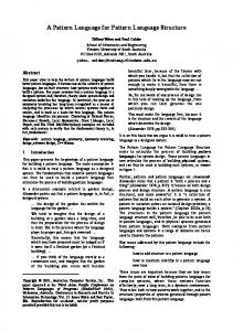
common module. The Virtual Machine Operating System Architecture provides virtual copies of the underlying hardware that can be used for execution of different OSs. Figure 1 describes the OS architectures in a pattern language, indicating their dependencies. The figure shows also two variants of the basic patterns.
Layered Modular Operating System Architecture
Modular Operating System Architecture Can run
Layered Operating System Architecture
Layered Microkernel Operating System Architecture
Can run
Virtual Machine Operating System Architecture
Can run
Microkernel Operating System Architecture
Figure 1. Pattern diagram of OS Architectures Computer system functionality can be divided between the kernel (or OS proper), components and the user dictated applications or utilities. Typically, an OS includes the following functional components: • • • • • • •
Process Management- handles creation and deletion of processes, communication and scheduling. Memory Management- keeps track of which parts of memory are used by which processes, allocates and deallocates memory. File Management- handles creation and deletion of files and directories, file searches, and mapping files to secondary storage I/O Management- provides interfaces to hardware device drivers , as well as handling mass memory management components including buffering, caching, and spooling. Networking- controls communication path between two or more systems. Protection System- includes authentication of users and file and memory protection. User Interface- communicates between user and OS including command interpreters.
These components may be further divided for specific applications. In [Fer02] and [Fer03] we presented patterns for the security of these functions. The four architectures we consider differ on how to structure the relationship of the components.
2
2
The Modular Operating System Architecture
Separate the OS services into modules each representing a basic function or component. In the modular approach, the basic kernel only has the required core components to start itself and the ability to load modules. The core module is the one module always in memory. Whenever the services of any additional modules are required, the module loader loads the correct module. Each small module performs a function and may take parameters. For example, a web browser uses an HTML renderer to display a webpage. In turn, the HTML renderer uses a jpg-renderer to display jpg images.
2.1 Example We are building a new OS that should support various types of devices requiring dynamic services with a large variety of security requirements. We want to dynamically add OS components, functions, and services, as well as tailor their security aspects according to the type of application. For example, a media player may require support to prevent copying of the contents.
2.2 Context A variety of applications with diverse requirements that need to execute together sharing hardware resources.
2.3 Problem We need to be able to add/ remove functions in the easiest way. How do we structure the functions for this purpose? The possible solution is constrained by the following forces: • OSs for PCs and other types of uses require a large variety of plug-ins. New plugins appear frequently and we need the ability to add and remove them without disrupting normal operation. For example, we could remove a module for which a vulnerability alert has been issued. • Some of the plug-ins may contain malware, we need to isolate their execution so they do not affect other processes. • We would like to hide security-critical modules from other modules to avoid possible attacks.
2.4 Solution Define a core component that can dynamically load and link modules as needed. Structure Figure 2 shows a class diagram for the Modular Operating System Architecture pattern. The KernelCore is the core of the Modular OS. A set of LoadableModules is associated with the KernelCore, indicating the modules that could be loaded. Any LoadableModule can call any other LoadableModule.
3
Can call *
LoadableModule
1
*
KernelCore
*
Figure 2. Class diagram for the Modular Operating System Architecture pattern
2.5 Implementation --Separate the functions of the OS into independent modules according to whether: • They are complete functional units. • They are critical with respect to security. • They should execute in their own process or thread for performance reasons. • They should be isolated during execution because they may contain malware. --Define a communication structure for the resultant modules. Operations should have well defined call signatures and all calls should be checked. --Define a preferred order for loading some basic modules. Modules that are critical for security should be loaded only when needed.
2.6 Example resolved We structured the functions of our system following the Modular Architecture pattern. Because each module could have its own address space, we can isolate its execution. Because each module can de designed independently, they can have different security constraints in their structure. This structure gives us flexibility with a good degree of security.
2.7 Variants Monolithic kernel. The operating system is a collection of procedures. Each procedure has a well defined interface in terms of parameters and results and each one is free to call any other one [Tan01]. There is no structure or control between operating system, components, services, and user applications. The difference between monolithic and modular is that in the monolithic approach, all the modules are loaded together at installation time, instead of being brought on demand. As indicated earlier, this approach is not very attractive for secure systems.
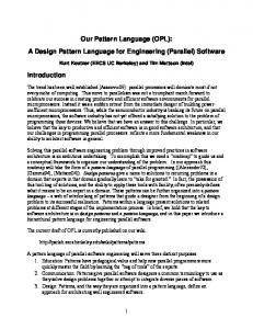
2.8 Known uses The Solaris 10 Operating System (Figure 3) is designed in this way. Its kernel is dynamic and composed of a core system that is always resident in memory [Sun04]. Another example is ExtremeWare from Extreme Networks [Ext]. Some versions of Linux are somewhat in between modular and monolithic.
4
device and bus drivers
miscellaneous modules
scheduling classes file systems
core Solaris kernel
STREAMS modules
loadable System calls
executable formats
Figure 3. The modular design of the Solaris 10 Operating System [Sil03]
2.9 Consequences The Modular Operating System Architecture Pattern has the following advantages: • Flexibility to add/ remove functions contributes to security in that we can add new versions of modules with better security. • Each core component is separate and talks to the others over known interfaces. We can introduce controls in these interfaces. • It is possible to partially hide critical modules by loading them only when needed and removing them after use. • By giving each executing module its own address space we can isolate the effects of a rogue module. The Modular Operating System Architecture Pattern has the following liabilities: • Any module can see all the others and potentially interfere with their execution. • Uniformity of call interfaces between modules makes it difficult to apply stronger security restrictions to critical modules.
2.10 Related patterns The Controlled Execution Environment pattern [Fer0] can be used to isolate executing modules. Thread patterns [Sch00] – Each module will typically run in its own thread.
5
3
The Layered Operating System Architecture
The overall features and functionality of the OS are decomposed and assigned to hierarchical layers. This provides clearly defined interfaces between each section of the operating system and between user applications and the OS functions. Layer i uses services of a lower layer i-1 and does not know the existence of a higher layer i+1.
3.1 Example Our system is very complex and we would like to separate different aspects in order to handle them in a more systematic way. Complexity brings along vulnerability. We also want to control the calls between OS components and services to improve security and reliability. Finally, we would like to hide critical modules. We tried a modular architecture but it did not have enough structure to do all this systematically.
3.2 Context A variety of applications with diverse requirements that need to execute together sharing hardware resources.
3.3 Problem Unstructured modules as in the previous architecture have the problem that all modules know about the existence of all other modules. This facilitates attacks. We need to hide the existence of some critical modules. The possible solution is constrained by the following forces: • Interfaces should be stable and well defined. Going through any interface could imply authorization checks. • Parts of the system should be exchangeable or removable without affecting the rest of the system. For example, we could have modules that perform more security checks than others. • Similar responsibilities should be grouped to help understandability and maintainability. This contributes indirectly to improve security. • We should control module visibility to avoid possible attacks from other modules. • Complex components need further decomposition. This makes the design simpler and clearer and also improves security.
3.4 Solution Define a hierarchical set of layers and assign components to each layer. Each layer presents an abstract machine to the layer above it, hiding implementation details of the lower layers. Structure Figure 4 shows a class diagram for the Layered Operating System Architecture pattern. Layer N represents the highest level of abstraction, and Layer 1 is the lowest level of abstraction. The main structural characteristic is that the services of Layer N are used only by Layer N + 1. Each layer may contain complex entities consisting of different components.
6
C lie n t
L a y e rN
1
L a y e rN -1
. . .
1
L a y e r2
1
L a y e r1
Figure 4. Class diagram for Layered Operating System Architecture pattern Dynamics In Figure 5, a user wishes to open a file located on a disk: • A user sends an openFile( ) request to the OSInterface • The OSInterface interprets the openFile( ) request • The openFile( ) request is sent from the OSInterface to the FileManager • The FileManager sends readDisk( ) request to the DiskDriver
aUser:
:OSInterface
:FileManager
:DiskDriver
openFile(…)
openFile(…) readDisk(…)
Figure 5. Sequence diagram for opening and reading a disk file
3.5 Implementation •
List all units in the system and define their dependencies.
7
• •
•
Assign units to levels such that units in higher levels depend only on units of lower levels. Once the modules in a given level are assigned, define a language for this level. This language includes the operations that we want to make visible to the next level above. Add well-defined operation signatures and security checks in these operations to assure the proper use of the level. Hide in lower levels those modules that control critical security functions.
3.6 Example resolved We structured the functions of our system as in Figure 6 and now we have a way to control interactions and enforce abstraction. For example, the file system can use the operations of the disk drives and enforce similar restrictions in the storage of data. The user of the file cannot take advantage of the implementation details of the disk driver to attack the system.
users
UserApplication
Layer 5
Utilities
Layer 4
FileSystem
Layer 3
I/Odrives
Layer 2
Hardware
Layer 1
utilities
file system
I/O drives
disk drives
hardware
...
Figure 6. An example of the use of a Layered OS architecture.
3.7 Variants Layer skipping. In this architecture there are special applications able to skip layers for added performance. This structure requires a tradeoff between performance and security. By deviating from the strict hierarchy of the layered system, there may not be enforcement of security policies between layers for these applications.
3.8 Known uses The Symbian OS (Figure 7) uses a variation of the layered approach [Sym01].
8
Connectivity framework
Application services
Application protocols
Connectivity plug-ins
Application engines
Messaging
WAP browser
Web browser
Application framework
Narrow band protocols
WAP Stack
Web Stack
Multimedia
Graphics
JavaPhone JavaRuntime Infrared Bluetooth Networking
Comms infrastructure
Security
Connectivity link
Serial Comms
Telephony
Base
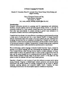
Figure 7. Symbian OS Layered Architecture [Sym01] The UNIX operating system (Figure 8) is separated into 4 layers with clear interfaces between the system calls to the kernel and between the kernel and the hardware.
Figure 8. UNIX OS Layered Architecture [Sil05] IBM’s OS/2 also uses this approach [OS2].
3.9 Consequences The Layered Operating System Architecture Pattern has the following advantages:
9
• • • •
Lower levels can be changed without affecting higher layers. We can add or remove security functions as needed. Clearly defined interfaces between each OS layer and the user applications improve security. Control of information using layer hierarchical rules, using enforcement of security policies between layers. The fact that layers hide implementation aspects is useful for security in that possible attackers cannot exploit lower level details.
The Layered Operating System Architecture Pattern has the following liabilities: • It may not be clear what to put in each layer; in particular related modules may be hard to allocate. There may be conflicts between functional and security needs when allocating modules. • Performance may decrease due to the indirection of calls through several layers. If we try to improve performance we may sacrifice security.
3.10 Related patterns This pattern is a specialization of the Layers architectural pattern [Bus96]. Security versions of the Layers pattern have appeared in [Fer02] and in [Yod97].
4
The Microkernel Operating System Architecture
Move as much of the OS functionality from the kernel and put it in specialized servers, coordinated by a microkernel. The microkernel itself has a very basic set of functions. OS components and services are implemented as external and internal servers.
4.1 Example We are building an OS for a range of applications with different reliability and security requirements and a variety of plug-ins. We would like to provide OS versions with different types of modules, some more secure, some less so.
4.2 Context A variety of applications with diverse requirements that need to execute together sharing hardware resources.
4.3 Problem In general purpose environments we need to be able to add new functionality with variation in security and other requirements as well as provide alternative implementations of services to accommodate different application requirements. The possible solution is constrained by the following forces: • The application platform must cope with continuous hardware and software evolution; these additions may have very different security or reliability requirements.
10
• • •
Strong security or reliability requirements indicate the need for modules with well-defined interfaces. We may want to perform different types of security checks in different modules, depending their security criticality. We would like a minimum of functionality in the kernel so we have a minimum of processes running in supervisor mode. A simple kernel can be checked and this is good for security.
4.4 Solution Separate all functionality into specialized services with well-defined interfaces and provide an efficient way to route requests to the appropriate servers. Each server can be built with different security constraints. The kernel mostly routes requests to servers and has minimal functionality. Structure The Microkernel is the central communication for the OS. There is one Microkernel and several internal and external servers, each providing a set of specialized services (Figure 9). In addition to the servers, an Adapter is used between the Client and the microkernel or an external server. The Microkernel controls the internal servers. ExternalServer *
calls
1
execute mechanism init communication find receiver call internal server send message create handle (unique ID)
receive request dispatch request execute service
*
Microkernel
1
InternalServer receive request dispatch request execute service
*
1
calls Initializes communication
1
sends request
1
Adapter calls service creates request
1 1 calls service
Client do task
Figure 9. Class diagram for Microkernel Operating System Architecture pattern Dynamics A client requests a service from an external server using the following sequence (Figure 10): • The adapter receives the request and asks the microkernel for a communication link with the external server. • The microkernel checks for authorization to use the server, determines the physical address of the external server and returns it to the adapter • The adapter establishes a direct communication link with the external server.
11
• • •
The adapter sends the request to the external server using a procedure call or a remote procedure call (RPC). The RPC can be checked for well-formed commands, correct size and type of parameters (we can check signatures). The external server receives the request, unpacks the message and delegates the task to one of its own methods. All results are sent back to the adapter. The adapter returns to the client, which in turn continues with its control flow.
:Client call service
:Adapter
:Microkernel
:ExternalServer
create request
init communication
receiverHandle
find receiver check authorization
receive request
check signature
dispatch request
execute service returnResult
returnResult
Figure 10. Sequence diagram for performing an OS call through the microkernel
4.5 Implementation •
• • • • • •
Identify the core functionality necessary for implementing external servers and their security constraints. Typically, basic functions of the OS should be internal servers, utilities, or user-defined services should go into external servers. Each server can use the patterns from [Fer02] and [Fer03] for their secure construction. Define policies to restrict access to external and internal servers. Clients may be allowed to call only some specific servers. Find a complete set of operations and abstractions for every category identified. Determine strategies for request transmission and retrieval. Structure the microkernel component. The microkernel should be simple enough to make sure of its security properties (no malware for example). Design and implement the internal servers as separate processes or shared libraries. Add security checks in each server. Implement the external servers. Add security checks in each service provided by the servers.
4.6 Example resolved By implementing our system using a microkernel we can have several versions of each service, each with different degrees of security and reliability. We can replace servers dynamically if needed. We can also control access to specific servers and make sure that they are called in the proper way. 12
4.7 Variants Layered Microkernel. The Microkernel OS Architecture Pattern can be combined with the Layered OS Architecture pattern. In this case, servers can be assigned to levels and a call is accepted only if it comes from a level above the server level.
4.8 Known uses The PalmOS Cobalt (Figure 11). This OS has a preemptive multitasking kernel that provides basic task management. Many applications in the PalmOS do not use the microkernel services; they are handled automatically by the system. The microkernel functionality is provided for internal use by system software or for certain special purpose applications [PalmOS].
68K Applications ARM Applications PACE
Palm OS Application Compatibility Environment
Background
PIM System
Licensee Tasks
Graphics/ UI
Media playback
Multimedia HotSync
Data Manager
Microkernel
Exchange Security
Internal storage
I/O Subsystem Networking
VFS Telephony
Hardware Driver Set
Figure 11. PalmOS Microkernel combined with Layered OS Architecture [PalmOS]. The QNX Microkernel (Figure 12) is intended mostly for communication and process scheduling [QNX].
13
Process A
Process B
IPC
Process C
Network Interface
Network Manager
Scheduler Interrupt redirector
Network media
Hardware interrupts
Figure 12. QNX Microkernel Architecture [QNX] Mach and Windows NT also use some form of microkernels {Sil05].
4.9 Consequences The Microkernel Operating System Architecture Pattern has the following advantages: • Flexibility and extensibility – if you need an additional function or an existing function with different security requirements you only need to add an external server. Extending the system capabilities or requirements only require addition or extension of internal servers. • The Microkernel mediates all calls for services and can apply authorization checks. In fact, the microkernel is in effect, a concrete realization of a reference monitor [Fer01]. • The well-defined interfaces between servers allow each serve to check each request for their services. • Can add even more security by putting fundamental functions in internal servers. • Servers usually run in user mode, which further increases security. • The microkernel is very small and can be verified or checked for security. The Microkernel Operating System Architecture Pattern has the following liabilities: • Communication overhead since all messages go through the Microkernel.
4.10 Related patterns This pattern is a specialization of the microkernel pattern [Bus96]. As indicated, the microkernel itself is a concrete version of the Reference Monitor [Fer01].
14
5
The Virtual Machine Operating System Architecture
Provides a set of replicas of the hardware architecture (Virtual Machines), that can be used to execute (maybe different) operating systems with a strong isolation between them.
5.1 Example A web server is hosting applications for two competing companies. These companies use different operating systems. We want to ensure that neither of them can access the other company’s files or launch attacks against the other system.
5.2 Context Mutually suspicious sets of applications that need to execute in the same hardware. Each set requires isolation from the other sets.
5.3 Problem Sometimes we need to execute different operating systems in the same hardware. How do we keep those operating systems isolated from each other in such a way that their executions don’t interfere with each other? The possible solution is constrained by the following forces: • Each operating system needs to have access to a complete set of hardware features to support its execution. • Each OS has its own set of machine dependent features, e.g., interrupt handlers. In other words, each operating system uses the hardware in different ways. • When an OS crashes or it is penetrated by a hacker, the effects of this situation should not propagate to other OSs in the same hardware. • There should be no way for a malicious user in a VM to get access to the data or functions of another VM.
5.4 Solution Define an architectural layer that is in control of the hardware and supervises and coordinates the execution of each OS environment. This extra layer, usually called a Virtual machine Monitor (VMM) or Hypervisor presents to each operating system a replica of the hardware. The VMM intercepts all system calls and interprets them according to the OS from where they came. Structure Figure 13 shows a class diagram for the Virtual Machine Operating System Architecture (VMOS). The VMOS contains one VirtualMachineMonitor and multiple Virtual Machines (VM). Each VM can run a Local Operating System (LocalOS). The Hypervisor supports each LocalOS and is able to interpret its system calls. As a LocalProcess runs on a LocalOS the VM passes the OS system calls to the Hypervisor which executes them in the hardware.
15
VMOS
1
V irtu a lM a c h in e M o n ito r
*
< < c o n trols > >
VM * C a n ru n
*
S u p p orts
* *
L o c alO S
1
H a rd w a re *
L o c a lP ro c e ss
Figure 13. Class diagram for the Virtual Machine Operating System pattern Dynamics In Figure 14 a local process wishing to perform a system operation uses the following sequence: • A LocalProcess makes an OScall to the LocalOS. • The LocalOS maps the OS call to the VMM (by executing a privileged operation). • The VMM interprets the call according to the local OS from where it came and it executes the operation in the hardware. • The Hypervisor sends return codes to the LocalOS to indicate successful instruction execution as well as results of the instruction execution. • The LocalOS sends the return code and data to the LocalProcess.
5.5 Implementation • • •
Select the hardware that will be virtualized. All of its privileged instructions must trap when executed in user mode (this is the usual way to intercept system calls). Define a representation (data structure) for describing OS features that map to hardware aspects, e.g. meaning of interrupts, disk space distribution, etc. and build tables for each operating system to be supported. . Enumerate the system calls for each supported OS and associate them with specific hardware instructions.
16
:LocalP rocess
:LocalOS
:VirtualM achineM onitor
:Hardware
O S call O S call interpretC all perform O peration return(… ) return(… )
Figure 14. Sequence diagram for performing an OS call on a virtual machine
5.6 Example resolved In the example of Figure 15, two companies using Unix and Linux can execute their applications in different virtual machines. The VMM provides a strong isolation between these two execution environments.
U N IX
L in u x
VM1
VM2
V M M ( v ir tu a l m a c h in e m o n ito r ) h a rd w a re
Figure 15. Virtual Machine OS example
5.7 Variants This architecture is orthogonal to the other three architectures discussed earlier and can execute any of them as local operating systems.
17
KVM/370 was a secure extension of VM/370 [Gol79]. This system included a formally verified security kernel and its VMs executed in different security levels, e.g. top secret, confidential, etc. In addition to the isolation provided by the VMM, this system also applied the multilevel model secure flow control.
5.8 Known uses • • • • •
IBM VM/370 [Cre81]. This was the first VMOS, it provided VMs for an IBM370 mainframe. VMware [Nie00]. This is a current system that provides VMs for Intel x86 hardware. Solaris10 [Sun04] calls the VMs “containers” and one or more applications execute in each container. Connectix [Con] produces virtual PCs to run Windows and other operating systems. Xen is a VMM for the Intel x86 developed as a project at the University of Cambridge, UK [Bar00].
5.9 Consequences The Virtual Machine Operating System Architecture Pattern has the following advantages: • The VMM intercepts and checks all system calls. The VMM is in effect a Reference Monitor [Fer01] and provides total mediation on the use of the hardware. This can provide a strong isolation between virtual machines [Ros05]. • Each environment (VM) does not know about the other VM(s), this helps prevent cross-VM attacks. • There is a well-defined interface between the VMM and the virtual machines. • The VMM is small and simple and can be checked for security. The Virtual Machine Operating System Architecture Pattern has the following liabilities: • All the VMs are treated equally. If one needs different security categories of VMs it is necessary to build specialized versions as done in KVM370 (see Variants). • Extra overhead in use of privileged instructions. • It is rather complex to let VMs communicate with each other (if this is needed).
5.10 Related patterns • •
Reference Monitor [Fer01]. As indicated, the VMM is a concrete version of a Reference Monitor. The operating system patterns in [Fer02] and [Fer03] can be used to implement the structure of a VMOS.
Acknowledgements The comments of our shepherd, Raphael Y. de Camargo, were very useful to improve this paper. This work was supported by a grant from DISA, administered by Pragmatics, Inc.
18
References [Bar00] P. Barham, B. Dragovic, K. Fraser, S. Hand, T. Harris, A. Ho, R. Neugebauer, I. Pratt, and A. Warfield, “Xen and the art of virtualization”, Procs. of the ACM Symp. on Operating System Principles, SOSP’03. [Bus96] F. Buschmann, R. Meunier, H. Rohnert, P. Sommerlad, M. Stal. PatternOriented Software Architecture: A System of Patterns, Volume 1. Wiley, 1996. [Con] Connectix Corp., “The technology of virtual machines”, white paper, San Mateo, CA, http://www.connectix.com [Cre81] R. J. Creasy, “The origin of the VM/370 Time-Sharing System”, IBM Journal of Research and Dev., vol. 25, No 5, 1981, 483-490. [Ext] Extreme Networks, http://www.extremenetworks.com/products/OS/ [Fer01] E.B.Fernandez and R. Pan “A pattern language for security models”, http://jerry.cs.uiuc.edu/~plop/plop2001/accepted_submissions/ [Fer02] E.B.Fernandez, "Patterns for operating systems access control", Procs. of PLoP 2002, http://jerry.cs.uiuc.edu/~plop/plop2002/proceedings.html [Fer03] E. B. Fernandez and J. C. Sinibaldi, “More patterns for operating system access control”, Proc. of the 8th European conference on Pattern Languages of Programs, EuroPLoP 2003, http://hillside.net/europlop, 381-398. [Gam95] E. Gamma, R. Helm,R. Johnson, and J. Vlissides, Design patterns –Elements of reusable object-oriented software, Addison-Wesley 1995. [Gol79] B.D. Gold, R.R. Linde, R.J. Peeler, M. Schaefer, J.F. Scheid, and P.D. Ward, “A security retrofit of VM/370”, Procs. of the Nat. Comp. Conf. (NCC 1979), 335-344. [Har02] H. Hartig, “Security Architectures Revisited”, Proceedings of the 10th ACM SIGOPS European Workshop (EW 2002), September 22—25 2002, Saint-Emilion, France, http://os.inf.tu-dresden.de/papers_ps/secarch.pdf [Nie00] “Examining VMware”, Dr. Dobbs Journal, August 2000, 70-76. [OS2] http://www-306.ibm.com/software/os/warp/ [Pfl03] C.P.Pfleeger, Security in computing, 3rd Ed., Prentice-Hall, 2003. http://www.prenhall.com [Pri04] T. Priebe, E.B.Fernandez, J.I.Mehlau, and G. Pernul, "A pattern system for access control ", in Research Directions in Data and Applications Security XVIII, C.
19
Farkas and P. Samarati (Eds.), Procs of the 18th. Annual IFIP WG 11.3 Working Conference on Data and Applications Security, Sitges, Spain, July 25-28, 2004, 235-249. [PalmOS] http://www.palmos.com/dev/tech/overview.html [Phi03] Philips, “Current Trends in Operating System kernels”, July 2003. http://db.ilug-bom.org.in/lug-authors/philip/docs/os-tech.html [QNX] QNX Software systems, http://www.qnx.com [Ros05] M. Rosenblum and T. Garfinkel, “Virtual machine monitors: Current technology and future trends”, Computer, IEEE May 2005, 39-47. [Sch00] D. Schmidt, M. Stal, H. Rohnert, and F. Buschmann, Pattern-oriented software architecture, vol. 2 , Patterns for concurrent and networked objects, J. Wiley & Sons, 2000. [Sha02] J.S.Shapiro and N. Hardy, “EROS: A principle-driven operating system from the ground up”, IEEE Software, Jan./Feb. 2002, 26-33. See also: http://www.eros-os.org [Sil05] A. Silberschatz, P. Galvin, G. Gagne, Operating System Concepts (7th Ed.), John Wiley & Sons, 2003. [Sun04] http://www.sun.com/software/whitepapers/solaris10/s10security.pdf [Sym01] http://www.symbian.com/developer/ [Tan01] A. Tanenbaum, Modern Operating Systems (2nd Ed.), Prentice Hall, 2001. [Yod97] J. Yoder and J. Barcalow, "Architectural patterns for enabling application security". Procs. PLOP’97, http://jerry.cs.uiuc.edu/~plop/plop97 Also Chapter 15 in Pattern Languages of Program Design, vol. 4 (N. Harrison, B. Foote, and H. Rohnert, Eds.), Addison-Wesley, 2000.
20