A PROOF AND AN ALTERNATIVE TO THEVENIN’S THEOREM USING ACTUAL AND VIRTUAL, VOLTAGE AND CURRENT-DIRECTION ANALYSIS OF A RESISTIVE ELECTRICAL CIRCUIT Benjamin Edun Department of Physics, Middle East Technical University, Ankara, Turkey Email:
[email protected]
Abstract: The objective of this paper is to use a unique mathematical analysis of a purely resistive electrical circuit to prove the validity of Thevenin’s theorem by analysing the relationship between voltages and resistances in a simple electrical circuit and deriving alternatives to Thevenin’s theorem. Introduction: Thevenin’s theorem, which was devised by Leon Charles Thevenin is largely used in the evaluation of complex electrical and electronic circuits. A detailed and elaborate mathematical proof would help students and researchers understand the principles that support it deeply, and satisfy the curiosity of Scientists and Engineers all over the world. I would particularly say that most of the proofs available used little or no mathematical approach. I therefore deemed it important that a clearly written mathematical proof will serve to further validate Thevenin’s theorem and providing alternatives will create options available for use in solving Circuit problems. Keywords: R1-Resistor 1 R2-Resistor 2 R3-Resistor 3 DIAGRAMS
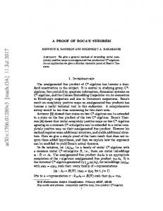
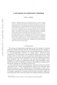
Diagram 1- Simple resistive Circuit
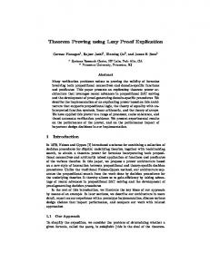
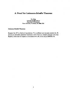
Diagram 2
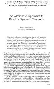
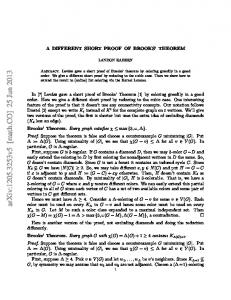
Diagram 3
Actual Voltage and Current-Direction analysis of
Virtual Voltage and Current-
Diagram 1
Direction analysis of Diagram 1 with Vx replacing V In the Circuit
Considering Diagram 2
The supply voltage is V and let voltage across R3 be V3 R1 is in series with R2 and R3 in parallel R2×R3
R2×R3
) / (R +R + R1 )) × V R +R
V3 = ((
2
3
R2×R3
V3 = ((
R2+R3
V3 =
2
3
(R2×R3)+(R1×R3)+(R1×R2)
)/(
R2+R3
R2×R3 (R3×R2) + (R1×R3) + (R1×R2)
Let, V3 =
)) × V
×V
R2×R3 (R3×R2) + (R1×R3) + (R1×R2)
× V be equation 1
Considering Diagram 3
Assume a virtual voltage V𝑥 in series R3 with is applied from the opposite end of the circuit. R3 is in series with R1 and R2 in parallel R1×R2
V3 = ((R3)/ (
R1+R2
+ R3)) × V𝑥
(R2×R3)+(R1×R3)+(R1×R2)
V3 = ((R3)/ (
R1+R2
R3 ×(R1+R2)
V3 = (
(R1×R3) + (R2×R3) + (R2×R3)
)) × V𝑥
) × Vx
Let V3 for equations 1 and 2 be equal Equation 1=equation 2
R2×R3 (R3×R2) + (R1×R3) + (R1×R2)
V𝑥 = (( V𝑥 = (R
(R1×R3) + (R2×R3) + (R2×R3)
) × V𝑥
R3 ×(R1+R2)
R2×R3
) / ((R ×R ) + (R ×R ) + (R ×R ))) × V (R ×R ) + (R ×R ) + (R ×R ) 3
2
R2
1
R3 ×(R1+R2)
×V=(
1
3
1
2
1
3
2
3
2
3
×V
+R2)
Let, V𝑥 = (R
R2
1
+R2)
× V be equation 3(Thevenin’s Conclusive equation)
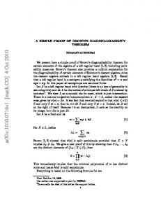
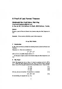
Hence the voltage needed to be applied as in diagram 2 to produce the same voltage across R3 as in diagram 1 is as in equation 3 Using the virtual voltage V𝑥 , circuit diagram 2 will be as below
Where Rx is the equivalent resistance of R1 and R2 in parallel
Alternative to Thevenin’s Theorem 1 In this case we will analyse Diagrams 1 and 2 for resistor R2 Considering Diagram 2
The supply voltage is V and let voltage across R2 be V2 R1 is in series with R2, both are in parallel with R3
R2×R3
R2×R3
) / (R +R + R1 )) × V R +R
V2 = ((
2
3
R2×R3
2
3
(R2×R3)+(R1×R3)+(R1×R2)
)/( R +R
V2 = (( V2 =
2
R2+R3
3
R2×R3 (R3×R2) + (R1×R3) + (R1×R2)
Let, V2 =
)) × V
×V
R2×R3 (R3×R2) + (R1×R3) + (R1×R2)
× V be equation 4
Considering Diagram 3
Assume a virtual voltage is applied in series with R3 from the opposite end of the circuit with VoltageV𝑥 . R2 is in parallel with R1, both are in series with R3
R2×R1
R2×R3
) / (R +R + R 3 )) × V𝑥 R +R
V2 = ((
2
1
R2×R1
2
1
(R2×R3)+(R1×R3)+(R1×R2)
)/( R +R
V2 = (( V2 =
2
R2+R1
1
R2×R1 (R3×R2) + (R1×R3) + (R1×R2)
Let, V2 =
× V𝑥
R2×R1 (R3×R2) + (R1×R3) + (R1×R2)
× V𝑥 be equation 5
Let V2 for equations 4 and 5 be equal Equation 4=equation 5
)) × V𝑥
R2×R3 (R3×R2) + (R1×R3) + (R1×R2)
×V=
R2×R1 (R3×R2) + (R1×R3) + (R1×R2)
R2×R3
× V𝑥
R2×R1
(((R ×R ) + (R ×R ) + (R ×R )) / ((R ×R ) + (R ×R ) + (R ×R ))) × V 3
Vx =
2
R3 R1
1
3
1
2
3
2
1
3
1
2
×V
Let, Vx =
R3 R1
× V be equation 6(Conclusive equation for Alternative 1)
Hence the voltage V𝑥 to be applied as in diagram 2 to produce the same voltage across R2 as in diagram 1 is as in equation 6 Using the virtual voltage V𝑥 , circuit diagram 2 would be as below
Voltage across R 𝑥 = Voltage across R2 Where Rx is the equivalent resistance of R1 and R2 in parallel
Alternative to Thevenin’s Theorem, 2 In this case we will analyse Diagrams 1 and 2 for resistor R1
Considering Diagram 2
The supply voltage is V and let voltage across R3 be V3 R1 is in series with R2 and R3 in parallel
R2×R3
V1 = ((R1)/ (
R2+R3
+ R1)) × V
(R2×R3)+(R1×R3)+(R1×R2)
V1 = ((R1)/ (
R2+R3
R1 ×(R2+R3)
V1 = (
(R1×R3) + (R2×R3) + (R2×R3)
)×V
R1 ×(R2+R3)
Let, V1 = (
)) × V
(R1×R3) + (R2×R3) + (R2×R3)
) × V be equation 7
Considering Diagram 3
Assume a virtual voltage V𝑥 in series with V is applied from the opposite end of the circuit. R3 is in series with R1 and R2 in parallel R2×R1
R2×R3
) / (R +R + R 3 )) × V𝑥 R +R
V1 = ((
2
1
2
1
(R2×R3)+(R1×R3)+(R1×R2)
R2×R1
)/( R +R
V1 = (( V1 =
2
R2+R1
1
R2×R1 (R3×R2) + (R1×R3) + (R1×R2)
Let, V1 =
)) × V𝑥
× V𝑥
R2×R1 (R3×R2) + (R1×R3) + (R1×R2)
× V𝑥 be equation 8
Let V1 for equations 7 and 8 be equal Equation 7=equation 8 R1 ×(R2+R3)
R2×R1
((R ×R ) + (R ×R ) + (R ×R )) × V = (R ×R ) + (R ×R ) + (R ×R ) × V𝑥 1
3
2
V𝑥 = (( V𝑥 =
3
2
3
3
2
1
R1 ×(R2+R3)
3
1
2
R2×R1
) / ((R ×R ) + (R ×R ) + (R ×R ))) × V (R ×R ) + (R ×R ) + (R ×R ) 1
3
(R2+R3) R2
Let, V𝑥 =
2
3
2
3
3
2
1
3
1
2
×V
(R2+R3) R2
× V be equation 9(Conclusive equation of Alternative 2)
Hence the voltage V𝑥 to be applied as in diagram 2 to produce the same voltage across R1 as in diagram 1 is as in equation 9 Using the virtual voltage V𝑥 , circuit diagram 2 would be as below
Voltage across R 𝑥 =Voltage across R1 Where R 𝑥 is the equivalent resistance of R1 and R2 in parallel Discussion: In both the proofs and alternatives, R 𝑥 is an equivalent circuit. Either equation 6 or 9 can be used in place of Thevenin’s theorem, but they correspond to finding the voltage and current characteristics R1 and R2 of respectively. Thus the same virtual voltage was assumed for all the three cases but different conclusions were drawn when different segments of the circuit were considered. Equations 6 and 9 can be used to supplement Thevenin’s theorem, or they can be used distinctively to find the voltage and current through the loads specified. In a typical conclusive Thevenin’s Circuit which includes both the equivalent circuit and the load, the characteristics of the loads in parallel to the load whose voltage and current are determined by Thevenin’s theorem can be determined also without solving for the load determined by Thevenin’s Theorem. If R3 is the load whose voltage and current characteristics is determined by Thevenin’s theorem, equation 6 would be useful in determining the current and voltage characteristics of the load R2 at right angle to R3 and equation 9 applies to the load R1 at 180 degrees to R3 where R1, R2, R3 form a T- current junction. It is important to note that every circuit to which the stated concepts would be applied to must be reduced to the form of diagram 3, inorder for the concepts indicated to be applicable. Conclusion: Thevenin’s theorem, and equations 6 and 9 are valid for analysing and condensing complex circuits. It can also be deduced from these derivations that Thevenin’s theorem, equations 6 and 9 rely on the creation of a virtual circuit-the equivalent circuit-to be useful. Thevenin’s theorem and the specified alternatives effectively account for the voltage across a particular load in the circuit. However in using Thevenin’s theorem or either of the alternatives, all other loads can assume different electrical states. Conclusively Thevenin’s theorem has been proofed and alternatives derived as intended. REFERENCES
Edun, B (2015). ‘’Proof of Thevenin’s Theorem Using Forward and Reverse Directional Analysis of an Electricla Circuit’’. ResearchGate. doi: 10.13140/RG.2.1.5116.8169. Retrieved from https://www.researchgate.net/publication/276272738.
Johnson, D.H. (2003a). "Origins of the equivalent circuit concept: the voltage-source equivalent" (PDF). Proceedings of the IEEE 91 (4): 636–640. doi:10.1109/JPROC.2003.811716 Brittain, J.E. (March 1990). "Thevenin's theorem". IEEE Spectrum 27 (3): 42. doi:10.1109/6.48845. Retrieved 1 February 2013 Dorf, Richard C.; Svoboda, James A. (2010). "Chapter 5 - Circuit Theorems". Introduction to Electric Circuits (8th ed.). Hoboken, NJ: John Wiley & Sons. pp. 162–207. ISBN 978-0-47052157-1