a hierarchical structure of characteristics, each of which contributes to total quality. .... The ability to represent and manipulate complex models that might never.
A Quality Model for Design Patterns Khashayar Khosravi
Yann-Ga¨el Gu´eh´eneuc
Summer 2004
Abstract Design patterns are high level building blocks that are claimed to promote elegance in object-oriented programs by increasing flexibility, scalability, usability, reusability, and robustness. However, there is some evidence that design patterns do not intrinsically promote quality. We believe that the problem of quality with design patterns comes both from the design patterns themselves and from their misuse. Unfortunately, little work has attempted so far to study the quality characteristics of design patterns rigorously. The objective of this technical report is to introduce a quality model and metrics that help in assessing the quality characteristics of design patterns and in concluding on design patterns quality. We begin with a summary of definitions on quality and related concepts and by introducing the most common and standard quality models. Then, we define characteristics of the models in details and present the metrics used to measure programs. Some of the most common characteristics of quality models introduced are used to develop a quality model to assess and measure the quality characteristics that design patterns claim to possess.
Contents 1 Quality Models 1.1 Quality . . . . . . . . . . 1.2 Quality Evaluation . . . . 1.2.1 Quality Model . . 1.2.2 Quality Factor . . 1.2.3 Quality Sub-factor 1.2.4 Quality Criterion . 1.2.5 Quality Metric . . 1.2.6 Internal Quality . 1.2.7 External Quality . 1.2.8 Quality in Use . .
. . . . . . . . . .
. . . . . . . . . .
. . . . . . . . . .
. . . . . . . . . .
. . . . . . . . . .
. . . . . . . . . .
. . . . . . . . . .
. . . . . . . . . .
. . . . . . . . . .
. . . . . . . . . .
. . . . . . . . . .
. . . . . . . . . .
. . . . . . . . . .
. . . . . . . . . .
. . . . . . . . . .
. . . . . . . . . .
. . . . . . . . . .
. . . . . . . . . .
. . . . . . . . . .
3 3 4 4 5 5 5 6 6 6 6
2 Quality Models 2.1 Hierarchical Models . . . . . . . 2.1.1 McCall’s Model (1976-7) . 2.1.2 Boehm’s Model (1978) . . 2.1.3 FURPS Model (1987) . . 2.1.4 ISO/IEC 9126 (1991) . . 2.1.5 Dromey’s Model (1996) . 2.2 Non-hierarchical Models . . . . . 2.2.1 Bayesian Belief Networks 2.2.2 Star Model . . . . . . . . 2.3 Quality Characteristics . . . . . . 2.3.1 Definitions . . . . . . . . 2.3.2 Summary . . . . . . . . . 2.3.3 Relationships . . . . . . .
. . . . . . . . . . . . .
. . . . . . . . . . . . .
. . . . . . . . . . . . .
. . . . . . . . . . . . .
. . . . . . . . . . . . .
. . . . . . . . . . . . .
. . . . . . . . . . . . .
. . . . . . . . . . . . .
. . . . . . . . . . . . .
. . . . . . . . . . . . .
. . . . . . . . . . . . .
. . . . . . . . . . . . .
. . . . . . . . . . . . .
. . . . . . . . . . . . .
. . . . . . . . . . . . .
. . . . . . . . . . . . .
. . . . . . . . . . . . .
. . . . . . . . . . . . .
8 8 8 9 10 11 12 14 14 15 16 16 27 28
3 Quality Metrics 3.1 Metrics . . . . . . . 3.2 Quality Metrics . . . 3.2.1 Adaptability 3.2.2 Completeness 3.2.3 Complexity . 3.2.4 Conciseness .
. . . . . .
. . . . . .
. . . . . .
. . . . . .
. . . . . .
. . . . . .
. . . . . .
. . . . . .
. . . . . .
. . . . . .
. . . . . .
. . . . . .
. . . . . .
. . . . . .
. . . . . .
. . . . . .
. . . . . .
. . . . . .
30 30 31 31 31 32 35
. . . . . .
. . . . . .
. . . . . .
. . . . . . . . . .
. . . . . .
. . . . . . . . . .
. . . . . .
. . . . . . . . . .
. . . . . .
1
. . . . . .
. . . . . . . . . . . . . . . . . . . . . . .
. . . . . . . . . . . . . . . . . . . . . . .
. . . . . . . . . . . . . . . . . . . . . . .
. . . . . . . . . . . . . . . . . . . . . . .
. . . . . . . . . . . . . . . . . . . . . . .
. . . . . . . . . . . . . . . . . . . . . . .
. . . . . . . . . . . . . . . . . . . . . . .
. . . . . . . . . . . . . . . . . . . . . . .
35 35 37 38 38 39 39 40 41 42 42 42 43 43 46 47 47 47 48 48 51 52 53
4 Design Patterns 4.1 Introduction . . . . . . . . . . . . . . . . . . . . . . . 4.2 Why Design Patterns? . . . . . . . . . . . . . . . . . 4.3 Quality Characteristics related with Design Patterns 4.4 Quality evaluation of Design Patterns . . . . . . . . 4.4.1 Creational Design Patterns . . . . . . . . . . 4.4.2 Structural Design Patterns . . . . . . . . . . 4.4.3 Behavioral Design Patterns . . . . . . . . . . 4.5 Summery . . . . . . . . . . . . . . . . . . . . . . . .
. . . . . . . .
. . . . . . . .
. . . . . . . .
. . . . . . . .
. . . . . . . .
. . . . . . . .
. . . . . . . .
56 56 56 56 57 58 63 72 85
3.3 3.4
3.2.5 Correctness . . . . . . . 3.2.6 Efficiency . . . . . . . . 3.2.7 Expendability . . . . . . 3.2.8 Generality . . . . . . . . 3.2.9 Hardware independence 3.2.10 Indicesability . . . . . . 3.2.11 Learnability . . . . . . . 3.2.12 Modularity . . . . . . . 3.2.13 Maturity Index . . . . . 3.2.14 Operability . . . . . . . 3.2.15 Portability . . . . . . . 3.2.16 Readability . . . . . . . 3.2.17 Reliability . . . . . . . . 3.2.18 Robustness . . . . . . . 3.2.19 Scalability . . . . . . . . 3.2.20 Simplicity . . . . . . . . 3.2.21 Software independence . 3.2.22 Structuredness . . . . . 3.2.23 Traceability . . . . . . . 3.2.24 Understandability . . . 3.2.25 Usability . . . . . . . . Our Model in a Nutshell . . . . Enhancing our Model . . . . .
5 Conclusions
. . . . . . . . . . . . . . . . . . . . . . .
. . . . . . . . . . . . . . . . . . . . . . .
. . . . . . . . . . . . . . . . . . . . . . .
. . . . . . . . . . . . . . . . . . . . . . .
. . . . . . . . . . . . . . . . . . . . . . .
. . . . . . . . . . . . . . . . . . . . . . .
. . . . . . . . . . . . . . . . . . . . . . .
. . . . . . . . . . . . . . . . . . . . . . .
. . . . . . . . . . . . . . . . . . . . . . .
. . . . . . . . . . . . . . . . . . . . . . .
. . . . . . . . . . . . . . . . . . . . . . .
87
2
Chapter 1
Quality Models 1.1
Quality
Everyone agrees that software quality is the most important element in software development because high quality could reduce the cost of maintenance, test and software reusing. But quality has very different meanings for customers, users, management, marketing, developers, testers, quality engineers, maintainers, and support personnel. Many institutes and organizations have their own definitions of quality and their own quality characteristics. The software industry is going to grow up daily and “it is rather surprising that more serious and definitive work has not been done to date in the area of evaluating software quality” [9]. Moreover, Kitchenham (1989) notes that “quality is hard to define, impossible to measure, easy to recognize” [39, 54]. Also, Gilles states that quality is “transparent when presented, but easily recognized in its absence” [28, 54]. Furthermore, Kan (2000) explains that “Quality is not a single idea, but rather a multidimensional concept. The dimensions of quality include the entity of interest, the viewpoint on that entity, and quality attributes of that entity” [36]. Some organisations try to develop standard definitions for quality. We mow present some definitions of international and standard organisations [53]: • ISO 9126: “Software quality characteristic is a set of attributes of a software product by which its quality is described and evaluated”. • German Industry Standard DIN 55350 Part 11: “Quality comprises all characteristics and significant features of a product or an activity which relate to the satisfying of given requirements”. • ANSI Standard (ANSI/ASQC A3/1978): “Quality is the totality of features and characteristics of a product or a service that bears on its ability to satisfy the given needs”. • IEEE Standard (IEEE Std 729-1983): 3
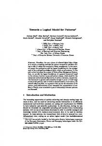
– The totality of features and characteristics of a software product that bear on its ability to satisfy given needs: For example, conformance to specifications. – The degree to which software possesses a desired combination of attributes. – The degree to which a customer or a user perceives that a software meets her composite expectations. – The composite characteristics of a software that determine the degree to which the software in use will meet the expectations of the customer. Figure 1.1 is meta-model of the relationships among requirements models and quality models.
Figure 1.1: Relationships among requirements models and quality models All these definitions give separate views on quality. Thus, we need to organise, clarify, and standardise the large number of quality-related definitions to obtain the best definitions for quality.
1.2
Quality Evaluation
Evaluation of quality requires models to link measures of software artifacts with external, high-level, quality characteristics. First, we introduce the concept of quality model, then we present the different elements related to quality models.
1.2.1
Quality Model
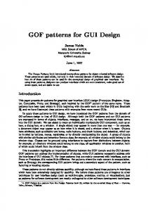
ISO/IEC 9126-1 defines a quality model as a “framework which explains the relationship between different approaches to quality” [33]. Quality models decomposes in hierarchical elements. An approach to quality is to decompose quality in Factors, Sub-factors, and criteria. Evaluation of a program begins 4
with measuring each quality criteria with numerical value from metrics. Then, each quality sub-factors is assessed using their criteria. Finally, numerical value are assigned to quality characteristics from their quality sub-factors. Figure 1.2 presents a meta-model of the relationships among quality model elements.
Figure 1.2: Relationship among quality model elements
1.2.2
Quality Factor
The typical objective of a quality factor is to characterize an aspect of the quality of a work product or a process [24].
1.2.3
Quality Sub-factor
Some factors can not refer directly to their criteria, they require a extra intermediate level to be computed. Elements of this intermediate level are sub-factors. For example, in Boehm’s model (Figure 2.2), maintainability1 as factor refers to three sub-factors: Testability, understandability, and modifiability. The typical objectives of a quality sub-factor are to [24]: • Characterize a part of a quality factor. • Further characterize an aspect of the quality of a work product or process. • Help in defining the term “quality” for an endeavor.
1.2.4
Quality Criterion
A quality criterion is the detailed description of the rationale for the existence of a factor or of a sub-factor. For example, in Boehm’s model, portability as a factor is described with two criteria: Device-independence and self confinedness. 1 All
the “-ility” are define in Section 2.3.
5
1.2.5
Quality Metric
We need to specify quality metrics to evaluate a given quality criteria. Each quality metric provides a numerical value that can be scaled to measure a quality factor. Metrics must be complete and detailed sufficiently to be the firm foundation of a quality model. “There is a strange relationship between internal and external quality. External quality is quality as measured by the customer. Internal quality is quality as measured by the programmers [6]” [17].
1.2.6
Internal Quality
N. Bevan defined the internal quality as characteristic “which is measured by the static properties of the code, typically by inspection (such as path length)” [7].
1.2.7
External Quality
External quality is defined as characteristics “which is measured by the dynamic properties of the code when executed (such as response time)” [7].
1.2.8
Quality in Use
ISO/IEC 9126-1 defines the quality in use as “the user’s view of quality. Achieving quality in use is dependent on achieving the necessary external quality, which in turns is dependent on achieving the necessary internal quality” [33], “which is measured by the extent to which the software meets the needs of the user in the working environment (such as productivity)” [7]. Quality in use decomposes into four characteristics [33]: • Effectiveness • Productivity • Safety • Satisfaction “Evaluation of software products in order to satisfy software quality needs is one of the process in the software development life-cycle. Software product quality can be evaluated by measuring internal attributes (typically static measure of intermediate products), or by measuring external attributes (typically by measuring the behavior of the code when executed), or by measuring quality in use attributes. The objective is for the product to have the required effect in a particular context of use” [33], see also Figure 1.3 . Using these definitions of quality and quality models, we now present the most common quality models defined in the literature.
6
Figure 1.3: Quality in the life-cycle
7
Chapter 2
Quality Models 2.1
Hierarchical Models
Several quality models have been defined by different people and organizations. In the following, we summarize briefly some of the most standard and wellknown quality models.
2.1.1
McCall’s Model (1976-7)
McCall’s model for software quality (see Figure 2.1) combines eleven criteria around product operations, product revisions, and product transitions. The main idea behind McCall’s model is to assess the relationships amon external quality factors and product quality criteria. “McCall’s Model is used in the United States for very large projects in the military, space, and public domain. It was developed in 1976-7 by the US Airforce Electronic System Decision (ESD), the Rome Air Development Center (RADC), and General Electric (GE), with the aim of improving the quality of software products” [53]. “One of the major contributions of the McCall model is the relationship created between quality characteristics and metrics, although there has been criticism that not all metrics are objective. One aspect not considered directly by this model was the functionality of the software product” [45]. The layers of quality model in McCall are defined as [11]: • Factors; • Criteria; • Metrics.
8
Figure 2.1: McCall’s model [48]
2.1.2
Boehm’s Model (1978)
Boehm added some characteristics to McCall’s model with emphasis on the maintainability of software product. Also, this model includes considerations involved in the evaluation of a software product with respect to the utility of the program (see Figure 2.2). “The Boehm model is similar to the McCall model in that it represents a hierarchical structure of characteristics, each of which contributes to total quality. Boehm’s notion includes users needs, as McCall’s does; however, it also adds the hardware yield characteristics not encountered in the McCall model” [45]. However, Boehm’s model contains only a diagram without any suggestion about measuring the quality characteristics. The layers of quality model in Boehm defined as [11]:
9
• High-level characteristics; • Primitive characteristics; • Metrics.
Figure 2.2: Boehm’s Model [9]
2.1.3
FURPS Model (1987)
The FURPS model proposed by Robert Grady and Hewlett-Packard Co. decomposes characteristics in two different categories of requirements: • Functional requirements (F): Defined by input and expected output. • Non-functional requirements (URPS): Usability, reliability, performance, supportability. Figure 2.3 is an example of the FURPS model. “One disadvantage of the FURPS model is that it fails to take account of the software product’s portability” [45].
10
Figure 2.3: FURPS Model
2.1.4
ISO/IEC 9126 (1991)
With the need for the software industry to standardize the evaluation of software products using quality models, the ISO (International Organization for Standardization) proposed a standard which specifies six areas of importance for software evaluation and, for each area, specifications that attempt to make the six area measurable (see Figure 2.4). “One of the advantages of the ISO 9126 model is that it identifies the internal characteristics and external quality characteristics of a software product. However, at the same time it has the disadvantage of not showing very clearly how these aspects can be measured” [45]. The layers of quality model in ISO/IEC are defined as [11]: • Characteristics; • Sub-characteristics; 11
• Metrics.
Figure 2.4: Software Quality ISO/IEC’s Model
2.1.5
Dromey’s Model (1996)
The main idea to create this new model was to obtain a model broad enough to work for different systems (see Figure 2.5). “He [Dromey] recognisees that evaluation differs for each product and you need a more dynamic idea for modelling the process” [21]. Dromey identified five steps to build his model: • Choose a set of high-level attributes that you need to use for your evaluation. • Make a list of all the components or modules in the system. • Identify quality-carrying properties for each component. (That is, qualities of the component that has the most impact on the product properties from the list created in last step). 12
• Decide on how each property affects the quality attributes. • Evaluate the model. • Identify and resolve weaknesses in with feedback loop. “Dromeys model seeks to increase understanding of the relationship between the attributes (characteristics) and the sub-attributes (sub-characteristics) of quality. It also attempts to pinpoint the properties of the software product that affect the attributes of quality” [45]. The layers of quality1 model in Dormey are defined as [11]: • High-level attributes; • Subordinate attributes.
Figure 2.5: Dromey’s Model
1 The
layers of quality in IEEE are defined as:
• Factors; • Sub-factors; • Metrics.
13
Figure 2.6 is an example of a Dromey’s model: • Evaluation of two components (variable and expression). • Definition of quality-carrying properties for variable and expression. • Definition of the product properties. • Obtention of the quality attributes for each product properties from Dromey’s model.
Figure 2.6: Example of Dromey’s Model
2.2 2.2.1
Non-hierarchical Models Bayesian Belief Networks
A BBN2 is a graphical networks whose nodes are the uncertain variables and whose edges are the causal or influential links between the variables, Associated with each node is a set of conditional probability functions that model the uncertain relationship between the node and its parents. It can be explained in two stages, one stage covers the life-cycle processes of specification, design or coding and the second stage covers testing [41, 40] . Using the BBN have some benefits as follow [41]: • BBNs enable reasoning under uncertainty and combine the advantages of an intuitive visual representation with a sound mathematical basis in Bayesian probability. 2 Bayesian
Belief Networks
14
• With BBNs, it is possible to articulate expert beliefs about the dependencies between different variables and to propagate consistently the impact of evidence on the probabilities of uncertain outcomes, such as future system reliability. • BBNs allow an injection of scientific rigour when the probability distributions associated with individual nodes are simply “expert opinions”. • A BBN will derive all the implications of the beliefs that are input to it; some of these will be facts that can be checked against the project observations, or simply against the experience of the decision makers themselves. • The ability to represent and manipulate complex models that might never be implemented using conventional methods3
2.2.2
Star Model
The Star model is introduced as follows: “The software quality Star is a conceptual model for presenting different perspectives of software quality. The model is based on the acquirer and supplier as defined in ISO/IEC 12207 (1995)” [53] There are three significant elements in the Star: The procurer (acquirer), the producer (supplier), and the product (see Figure 2.7). The procurer enters in a contract with the producer to create a software product. This contract clearly specifies the quality characteristics of the product. The procurer’s perspective of the producer organization is that they use the best project management techniques available and that they engage in first-rate processes to create a quality product. The procurer’s perspective of the product is that it must be acceptable by the user community and that it can be serviced and maintained by their professionals. The model considers that the acquirer be the lead party in any contractual arrangement because it is the acquirer’s users and technical support professionals who dictate the success or failure of the software product. Also, it is the acquirer who dictates the profile and maturity of the supplier organization. “The model accommodates the producer’s perspective of software quality and focuses on the maturity of the producer organization as software developers and the development processes that they used to create quality software products” [53].
3 BBNs have a rigorous, mathematical meaning there are software tools that can interpret them and perform the complex calculations needed in their use[41].
15
Figure 2.7: Star Model
2.3
Quality Characteristics
Definitions of quality characteristic have direct relations with the programming language and the environment for which a software product is implemented. For example, Lowell J. Arthur in 1951 defines the flexibility quality characteristic using the question: “Is the program free of spaghetti code?” [3], i.e., does the program source code contains GOTO instructions? Thus, this definition of the flexibility quality characteristic relates to pre-procedural structural programming directly and is no longer practical for object-oriented programs.
2.3.1
Definitions
In the following, we summarize standard or latest definitions for quality characteristics related to object-oriented programs and used in other sections of this report to define the quality models. These definitions are sorted alphabetically: • Accessibility: “Accessibility is the degree to which the user interface of something enables users with common or specified (e.g., auditory, visual, physical, or cognitive) disabilities to perform their specified tasks” [25]. “Does the model facilitate selective use of its parts for other purposes (e.g., for the construction of another model)?” [5] • Accountability: “Accountability: Does the model lend itself to measurement of its usage? Can probes be inserted to measure timing, whether specified branches are exercised, etc.?” [5] • Accuracy: “The capability of the software product to provide the right or agreed results or effects with the needed degree of precision” [62]. Also, “[t]he precision of computations and control” [49], the “[a]ttributes of 16
software that bear on the provision of right or agreed results or effects” [57], “the magnitude of defects (i.e., the deviation of the actual or average measurements from their true value) in quantitative data” [25]. “Are l;he models calculations and outputs sufficiently precise to satisfy their intended use?” [5] • Adaptability: “The capability of the software product to be adapted for different specified environments without applying actions or means other than those provided for this purpose for [/ by] the software considered” [62]. Also, “[a]ttributes of software that bear on the opportunity for its adaptation to different specified environments without applying other actions or means than those provided for this purpose for the software considered” [57]. Adaptability mostly considering as following options: – Independence of storage: We need to ensure that software modules are independent of storage size to make the software more adaptable. – Uncommitted memory: the ability to allocate address space without allocating memory to back it up at the same time – Uncommitted processing capacity: is defined as percentage of uncommitted processing capacity. • Adaptivity: “Adaptivity suggests that the system should be designed to the needs of different types of users” [1]. • Ambiguity: Attributes of software related with requirements with potential multiple meanings [31]. • Analyzability: “The capability of the software product to be diagnosed for deficiencies or causes of failures in the software, or for the parts to be modified to be identified” [62]. Also, the “[a]ttributes of software that bear on the effort needed for diagnosis of deficiencies or causes of failures, or for identification of part to be modified” [57]. • Attractiveness: “The capability of the software product to be attractive to the user” [62]. “Attractiveness is achieved through layout, graphics, color, and dynamic elements” [1]. • Auditability: “The ease with which conformance to standards can be checked” [49]. • Augmentability: The ability of “the model to accommodates expansion in component computational functions or data storage requirements” [5]. Attributes related to support the growth of data storage. • Availability: “Availability is the degree to which a work product is operational and available for use” [25] as a product or to uses. Availability has the same definition for malicious and non-malicious users. 17
• Behavior[62]: – Time behavior: “The capability of the software product to provide appropriate response and processing times and throughput rates when performing its function”. – Resource behavior: The attributes of software related with measuring the amount of resources required to perform its function. • Branding: “Branding is the degree to which a work product (e.g., application, component, or document) successfully incorporates the brand of the customer organization’s business enterprize” [25]. • Capacity: “Capacity is the minimum number of things (e.g., transactions, storage) that can be successfully handled.” [25]. • Configurability: “Configurability is the degree to which something can be configured into multiple forms (i.e., configurations)” [25]. • Changeability: “The capability of the software product to enable a specified modification to be implemented” [62]. Also, the “[a]ttributes of software that bear on the effort needed for modification, fault removal or for environmental change” [57]. Changeability is also called “modifiability” [1]. • Co-existence: “The capability of the software product to co-exist with other independent software in a common environment sharing common resources” [62]. • Compatibility: “Compatibility is the degree to which a system or a component can be used and functions correctly under specified conditions of the physical environment(s) in which it is intended to operate” [25]. • Completeness: “The degree to which full implementation of required function has been achieved” [49]. Also, completeness related to requirements, documentation, and comments: – Explain the program input and their presence with comments. – Don’t reference to dummy programs. • Compliance: “Attributes of software that make the software adhere to application-related standards of conventions or regulations in laws and similar prescriptions” [57]. Also, degree to which the software is found to “[c]omply with relevant standards and practices” [1]. In [62], compliance decomposes in: – Portability compliance: “The capability of the software product to adhere to standards or conventions relating to portability”. – Maintainability compliance: “The capability of the software product to adhere to standards or conventions relating to maintainability”. 18
– Efficiency compliance: “The capability of the software product to adhere to standards or conventions relating to efficiency”. – Usability compliance: “The capability of the software product to adhere to standards, conventions, style guides or regulations relating to usability”. – Reliability compliance: “The capability of the software product to adhere to standards, conventions or regulations relating to reliability”. – Functionality compliance: “The capability of the software product to adhere to standards, conventions or regulations in laws and similar prescriptions relating to functionality”. • Communication commonality: “The degree to which standard interfaces, protocols and bandwidths are used” [49]. • Communicativeness: “Does the model facilitate the specification of inputs? Does it provide outputs whose form and contenl, are easy to assimilate and useful?” [5] • Computability: Attributes related to computation safety (such as division by zero or other impossible computations). • Completeness: “Are all model inputs used within the model? Are there no dummy sub-models referenced?” [5] • Conformance: “Attributes of software that make the software adhere to standards or conventions relating to portability” [57]. • Conciseness: “The compactness of the program in terms of lines of code” [49]. Also, “Attributes of software that provide the implementation of a function with minimum amount of code” [64]. Conciseness relates to program excess, for example, unused entities (types, objects, parameters) or internal invocations of other functions within the same file decrease the value of conciseness. Conciseness answer the following questions: “Is the model implemented with a minimum amount of code? Is it excessively fragmented into sub-models so that the same sequence of code is not repeated in numerous places?” [5]. • Consistency: “Does the model contain uniform notation, terminology, and symbology within itself? Are all model attributes and variables typed and specified consistently for all uses? Are coding standards homogeneously adhered to?” [5] • Configurability: “The ability to organize and control elements of the software configuration” [49]. • Consistency: “The use of uniform design and documentation techniques throughout the software development project” [49]. For example: 19
– The set of global variables is supposed to be used across more than one sub program. – The type of variables is supposed to be consistent for all their uses. • Correctability: “Correctability is the ease with which minor defects can be corrected between major releases while the application or component is in use by its users” [25]. • Correctness: The “[e]xtent to which a program satisfies its specifications and fulfills the user’s mission objectives” [26, 49]. “Correctness is the degree to which a work product and its outputs are free from defects once the work product is delivered” [25]. Correctness answers the following typical questions: “Is the application and its data complete, accurate and consistent?” [3]. • Currency: “Currency is the degree to which data remain current (i.e., up to date, not obsolete)” [25]. • Data Commonality: “The use of standard data structures and types throughout the program” [49]. • Dependability: “Dependability is the degree to which various kinds of users can depend on a work product” [25]. • Device independability: – Factors for independency between computations and the computer configuration. – Factors for independency between computations and hardware capability, half word accessing, bit patterns. . . “Can the model be executed on other computer hardware configurations? Have machine-dependent statements been flagged and documented?” [5] • Effectiveness: “The capability of the software product to enable users to achieve specified goals with accuracy and completeness in a specified context of use” [62]. • Efficiency: “The capability of the software product to provide appropriate performance, relative to the amount of resources used, under stated conditions” [62]. “Efficiency is the degree to which something effectively uses (i.e., minimizes its consumption of) its resources. These resources may include all types of resources such as computing (hardware, software, and network), machinery, facilities, and personnel” [25]. Also, “[t]he amount of computing resources and code required by a program to perform a function” [26, 49], “[a] set of attributes that bear on the relationship between the level of performance of the software and the amount of resources used under stated conditions ” [57]. Efficiency relates to “shed load, end-toend error detection: Cheap test, Performance defects appear under heavy 20
load, safety first, scaling, throughput, latency, availability” [1]. “Does the model fulfill its objective without waste of resources?” [5] • Error tolerance: “The damage that occurs when the program encounters an error” [49]. • Expendability: “The degree to which architectural, data or procedural design can be extended” [49]. • Extendibility: The attributes related to the modification of a component or a system in case of increase of the storage or of the functional capacity [56]. • Extensibility: “Extensibility is the ease with which an application or component can be enhanced in the future to meet changing requirements or goals” [25]. Also, attributes related to new capabilities or to the modification of existing capabilities upon user needs [56]. • Fault Tolerance: “The capability of the software product to maintain a specified level of performance in cases of software faults or of infringement of its specified interface” [62]. Also, the “[a]ttributes of software that bear on its ability to maintain a specified level of performance in cases of software faults or of infringement of its specified interface” [57]. (“Use [of] robust methods to protect against permanent failure of a limited number of components. Use [of] stabilizing methods to protect against transitory faults” [1].) • Flexibility: “Effort required to modify an operational program” [26]. The effort to change or to modify a software product to adapt it to other environment or to other applications different from which it was designed. • Functionality: “The capability of the software product to provide functions which meet stated and implied needs when the software is used under specified conditions” [62]. Functionality is “[a] set of attributes that bear on the existence of a set of functions and their specified properties. The functions are those that satisfy stated or implied needs” [57]. Functionality “[i]s assessed by evaluating the feature set and capabilities of the program, the generality of functions that are delivered and the security of overall system” [49]. • Generality: “The breadth of potential application of program components” [49]. Generality is defined as the degree to which a software product can perform a wide range of functions. • Hardware independence: “The degree to which the software is decoupled from the hardware on which it operates” [49]. • Independence of storage: the ability to bring new storage where needed at a moments notice, more resilience and automatic failure recovery, enhanced performance, and cost savings from efficient storage use [27]. 21
• Indicesability: Attributes related to the degree of correctness of the software product throughout its development cycle [?]. • Initializability: Attributes related to the degree a software product can be initialized with the expected values [?]. item Installability: “The capability of the software product to be installed in specified environment” [62]. “Installability is the ease with which something can be successfully installed in its production environment(s)” [25]. Also, the “[a]ttributes of software that bear on the effort needed to install the software in a specified environment” [57]. • Instrumentation: “The degree to which the program monitors its own operation and identifies errors that do occur” [49]. • Integrity: The “[e]xtent to which access to software or data by unauthorized persons can be controlled” [26, 49]. Also, the attributes related to control a software product for illegal accesses to the program and its data [?]. • Interface facility: The degree to which two software products can be connected successfully. • Internationalization: “Internationalization (also known as globalization and localization) is the degree to which something can be or is appropriately configured for use in a global environment” [25]. • Interoperability: “The capability of the software product to interact with one or more specified systems” [62]. Also, the “[e]ffort required to couple one system with another” [26, 49], the “[a]ttributes of software that bear on its ability to interact with specified systems” [57], “the degree to which a system or one of its components is properly connected to and operates with something else” [25]. • Learnability: “The capability of the software product to enable the user to learn its application” [62]. Also, the “[a]ttributes of software that bear on the users’ effort for learning its application” [57]. “Learnability requires attention to the needs of the novice and uninitiated users. The uninitiated user is one that has no previous experience with the software or similar software. The novice user has either had some experience with similar software or has limited experience with the software” [1]. • Legibility: “Does the model possess the characteristic that its function is easily discerned by reading the code?” [5] • Maintainability: “The capability of the software product to be modified. Modifications may include corrections, improvements or adaptation of the software to change in environment, and in requirements and functional specifications” [62]. Also, the “[e]ffort required to locate and fix an error in an operational program” [26, 49]. “Maintainability is the ease with 22
which an application or component can be maintained between major releases” [25]. Also, “[a] set of attributes that bear on the effort needed to make specified modifications” [57], the degree of changing or modifying the components to correct errors, to improve performance, or to adapt for changing the environment [?]. • Maturity: “The capability of the software product to avoid failure as a result in the software” [62]. Also, the “[a]ttributes of software that bear on the frequency of failure by faults in the software” [57]. • Modularity: “The functional independence of program components” [49]. Modularity is increased when it is possible to divide each components into sub-components [?]. • Operability: “The capability of the software product to enable the user to operate and control it” [62]. Also, “[t]he ease of operation of a program” [49]. “Operability is the degree to which something enables its operators to perform their tasks in accordance with the operations manual” [25]. Also, the “[a]ttributes of software that bear on the users’ effort for operation and operation control” [57]. “Part of the design process for operability is to develop scenarios and use cases for novice, uninitiated, and expert users. Operability is enhanced through navigational efficiency, i.e., users can locate the information they want” [1]. • Performance: “Performance is the degree to which timing characteristics are adequate” [25]. Performance “[i]s measured by evaluating processing speed, response time, resource consumption, throughput, and efficiency” [49]. • Personalization: “Personalization is the degree to which each individual user can be presented with a unique user-specific experience” [25]. • Portability: “The capability of the software product to be transferred from one environment to another” [62]. Also, the “[e]ffort required to transfer a program from one hardware configuration and–or software system environment to another” [26, 49]. “Portability is the ease with which an application or component can be moved from one environment to another” [57, 25]. • Precision: “Precision is the dispersion of quantitative data, regardless of its accuracy” [25]. • Productivity: “The capability of the software product to enable users to expand appropriate amounts of resources in relation to the effectiveness achieved in specified context of use” [62]. • Readability: “Readability is characterized by clear, concise code that is immediately understandable” [3]. Readability is defined as the set of attributes related to the difficulty in understanding software components source and documentation. 23
item Recoverability: “The capability of the software product to re-establish a specified level of performance and recover the data directly affected in the case of failure” [62, 57]. Recoverability “[u]se[s] recovery oriented methods. System architecture should be designed with components that can be restarted independently of the other components. System architecture should be designed with an undo function to rewind time, untangle problems, and replay the system back to the current time” [1]. • Reliability: “The capability of the software product to maintain a specified level of performance when used under specified conditions” [62]. Reliability is the “Extend to which a program can be expected to perform its intended function with required precision” [26, 49]. It “[i]s evaluated by measuring the frequency and severity of failure, the accuracy of output result, the mean time between failure (MTBF), the ability to recover from failure and the predictability of the program” [49] because “Unreliable programs fail frequently, or produce incorrect data” [3]. Also, reliability is “[a] set of attributes that bear on the capability of software to maintain its level of performance under stated conditions for stated period of time” [57]. “Reliability is the degree to which a work product operates without failure under given conditions during a given time period” [25]. • Replaceability: “The capability of the software product to be used in place of another specified software product for the same purpose in the same environment” [62]. Also, “[a]ttributes of software that bear on opportunity and effort of using it in place of specified other software in the environment of software” [57]. • Requirements Risk: Attributes related to the risk of project failure because of requirements (as with poorly written or rapidly changing requirement). • Responsiveness: “Responsiveness is the ability of a system to meet its objectives for response time or throughput. In end-user systems, responsiveness is typically defined from a user perspective” [15]. • Resource utilization: “The capability of the software product to use appropriate amounts and types of resources when the software performs its function under stated conditions” [62]. • Reusability: “Reusability is the ease with which an existing application or component can be reused” [25]. It is the “[e]xtent to which a program can be used in other applications related to the packaging and scope of the functions that programs perform” [26, 49]. For example, reusability is possible when “[m]any modules contain two or more unique functions which, if separated from the main body of code, could be reused with other programs” [3]. Also, he attributes related to the cost of transferring a module or program to another application [?].
24
• Robustness: “Robustness is the degree to which an executable work product continues to function properly under abnormal conditions or circumstances” [25]. Also, the attributes related to the correct functioning of a software product in the case of invalid inputs or under stressful environmental conditions. “Does the model continue to execute reasonably when it is run with invalid inputs? Can the model assign default values to non-specified input variables and parameters? Does the model have the capability to check input data for domain errors?” [5] • Safety: “The capability of the software product to achieve acceptable levels of risk of harm to people business, software, property or the environment in specified context of use” [62]. • Satisfaction: “The capability of the software product to satisfy users in specified context of use” [62]. • Scalability: “Scalability is the ease with which an application or component can be modified to expand its existing capacities” [25]. “[S]calability is crucial for keeping costs down and minimizing interruptions in production” [42]. “Scalability is the ability of a system to continue to meet its response time or throughput objectives as the demand for the software functions increases” [15]. • Scheduleability: “Scheduleability is the degree to which events and behaviors can be scheduled and then occur at their scheduled times” [25]. • Security: “The capability of the software product to protect information and data so that unauthorized persons or systems cannot read or modify them and authorized persons or systems are not denied access to them” [62]. Also, security is “[t]he availability of mechanisms that control of protect programs and data” [49], “[a]ttributes of software that bear on its ability to prevent unauthorized access, where accidental or deliberate, to programs and data” [57]. • Self containedness: “Self containedness is related to the facility of the software product for initializing core storage prior to use and for proper positioning of input/output devices prior to use” [5]. • Self-descriptiveness: “Does the model contain enough information for a reader to determine or verify its objectives, assumptions, constraints, inputs, out,puts, components, and revision status?” [5] • Self documentation: “The degree to which the source code provides meaningful documentation” [49]. • Simplicity: “The degree to which a program can be understood without difficulty” [49].
25
• Software system independence: “The degree to which the program is independent of nonstandard programming language features, operating system characteristics, and other environmental constraints” [49]. • Stability: “The capability of the software product to avoid unexpected effects from modifications of the software” [62]. Also, the “[a]ttributes of software that bear on the risk of unexpected effect of modifications” [57]. • Structuredness: Does the model possess a definite pattern of organization of its interdependent parts? [5] • Subsetability: “Subsetability is the degree to which something can be released in multiple variants, each of which implements a different subset of the functional requirements and associated quality requirements” [25]. • Suitability: “The capability of the software product to provide an appropriate set of functions for specified tasks and user objectives” [62]. Also, the “[a]ttributes of software that bears on the presence and appropriateness of a set of functions for specified tasks” [57]. • Supportability: Supportability “combines the ability to extend the program (extensibility), adaptability and serviceability (these three attributes represent a more common term—maintainability), in addition to testability, computability, configurability, the ease with which a system can be installed and the ease with which problems can be localized” [49]. • Survivability: “Survivability is the degree to which essential, missioncritical services continue to be provided in spite of either accidental or malicious harm” [25]. • Testability: “The capability of the software product to enable modified software to be validated” [62]. Also, the “[e]ffort required to test a program to insure it performs its intended function” [26, 49]. ”Testability is the ease with which an application or component facilitates the creation and execution of successful tests (i.e., tests that would cause failures due to any underlying defects)” [25]. Also, the “[a]ttributes of software that bear on the effort needed for validating the modified software” [57]. • Traceability: “The ability to trace a design representation or actual program component back to requirements” [49]. Traceability is defined as the attributes that increase traceability among implementation, design, architecture, requirements. . . • Training: “The degree to which the software assists in enabling new users to apply the system” [49]. • Transferability: The attributes those related to the cost of transferring a software product from its original hardware or operational environment to another [?]. 26
• Transportability: “Transportability is the ease with which something can be physically moved from one location to another” [25]. • Trustability: “Trustability refers to the system’s ability to provide users with information about service correctness” [1]. • Uncommitted processing capacity is amounts of unattached processing capacity [20]. • Uncommitted memory: “Uncommitted memory enables an application to differentiate between reserving and using (committing) address space” [47] • Understandability: “The capability of the software product to enable the user to understand whether the software is suitable, and how it can be used for particular tasks and conditions of use” [62]. Also, the “[a]ttributes of software that bear on the users’ effort for recognizing the logical concept and its applicability” [57]. • Usability: “The capability of the software product to be understood, learned, used and attractive to the user, when used under specified conditions” [62]. Usability is related to the “set of attributes that bear on the effort needed for use, and on the individual assessment of such use, by a stated or implied set of users” [57, 7]. Also, usability is the “[e]ffort required to learn, operate, prepare input, and interpret output of program” [26, 49], “the ease with which members of a specified set of users are able to use something effectively” [25]. Usability “[i]s assessed by considering human factors, overall aesthetics, consistency, and documentation” [49]. • Utility: “Utility is the degree to which something can be accessed and used by its various types of users” [25]. • Variability: “Variability is the degree to which something exists in multiple variants, each having the appropriate capabilities” [25]. • Verifiability: “Verifiability is the ease with which an application or component can be verified to meet its associated requirements and standards” [25]. • Volatility: The attributes related to the requirements documents when the software product changes frequently. • Withdrawability: “Withdrawability is the ease with which an existing problematic version of the system or one of its components can be successfully withdrawn and replaced by a previously working version” [25].
2.3.2
Summary
In the following table, we have defined the software characteristics in relation to different software products.
27
Quality Characteristics Completeness Correctness Reliability Generality Understandability Efficiency Modularity Portability Reusability Adaptability Maintainability Flexibility Usability Testability Integrity Interoperability
All Products X [56] X [56] X [56]
Requirements Documentation X [56] X [56] X [56] X [56]
Design Documentation X [56] X [3] X [3] X [3] X [3] X [3] X [3] X [3]
Table 2.1: Interrelationships among software characteristics and software products
2.3.3
Relationships
Some quality characteristics are related to one another, we summarize these interrelationships among software quality characteristics, in Table 2.2.
28
Code X [56 X [56 X [56 X [56 X [56 X [56 X [56 X [56 X [3] X [56 X [56 X [3] X [3] X [3] X [3] X [3]
Adaptability Correctness Functionality Consistentability Modularity Descriptiveness Reliability Understandability Security Efficiency Integrity Maturity Suitability Accuracy Usability Communicativeness Conciseness Maintainability Consistency Testability Computability Error-Tolerance Flexibility Portability Completeness Execution-Efficiency Reusability Expendability Generality Hardware-Independence Operability Self-Documentation Interoperability Simplicity Software-Independence Storage-Efficiency Traceability Training
Adaptability Correctness Functionality Related[21]
Consistentability
Modula Not Related[3]
Related[21] Related[61]
Related[61] Not Related[3]
Related[21]
Not Related[3] Related[61] Not Related[3]
Related[21]
Related[2
Related Related[21]
Not Related[3] Related[33] Related[61]
Related[61]
Related[61]
Table 2.2: Interrelationships among quality characteristics
29
Related[21]
Related[6
Related[21]
Related[2
Related[21]
Related
Chapter 3
Quality Metrics 3.1
Metrics
Software metrics are used to quantify software, software development resources, and software development processes. Some software characteristics are measurable directly (as LOC-Lines Of Code), some other software characteristics can be inferred only from indirect measurements (for example, maintainability), and some software characteristics are mostly related to human perception (for example, understandability is more dependent to the people vs. the programs). Software metrics can be classified into three categories [37]: • Product metrics: Describe the characteristics of the product, such as size, complexity, design features, performance, and quality level. • Process metrics: Can be used to improve software development and maintenance process (i.e., effectiveness of defect removal during development, defect arrival, response time to fix defect). • Project metrics: Describe characteristics of the project and its execution (i.e., number of software developers, staffing pattern related to the life cycle of the software, cost, schedule, and productivity). However, some metrics belong to multiple categories (i.e., the in-process quality metrics of a project are both process metrics and project metrics). Moreover, a healthy metrics program focuses on much more than the measurement of programmer productivity. Consider these areas of software development which can benefit from a well-planned metrics program [63]: • Project management. • Product quality. • Product performance.
30
• Development process. • Cost and schedule estimation.
3.2
Quality Metrics
Software quality metrics are a subset of software metrics that focus on the quality characteristics of software products, processes, and projects. In the following, we present some quality characteristics and related quality metrics, which are used in most quality models as example: Adaptability, Completeness, Complexity, Conciseness, Correctness, Efficiency, Expendability, Generality, Hardware-independence, Indipesability, learnability, Modularity,Maturity index, Operability, Portability, Readability, Reliability, Robustness, Scalability, Simplicity, Software independence, Structuredness, Traceability, Understandability, and Usability.
3.2.1
Adaptability
• Independence of storage: Metrics used to measure independence of storage are: MIS : Number of modules which size constraints are hard-coded. MT otal : Number of modules with size constraints, is AIS = MMtotal • Uncommitted memory: Metrics used to measure the adaptability with respect to percentage of uncommitted memory are: MU M : Amount of uncommitted memory. MT otal : Total memory available. Mum AU M = M . total • Uncommitted processing capacity: Metrics used to measure the percentage of uncommitted processing capacity are: MU P C : Amount of uncommitted memory. MT otal : Total memory available. Mupc AU P C = Mtotal .
3.2.2
Completeness
Completeness can be measured in different ways: • First [56]: We need a model to identify the software requirements which are incomplete and ambiguous. Ambiguities are defined as any cause with no effect, and effect with no cause, and any combination of cause and effects that are inconsistent with the requirements or are impossible to achieve. AExisting = Number of remaining ambiguities. 31
AT otal = Number³ of identified ´ ambiguities. AExisting Completeness = 1 − AT otoal . To avoid division by zero, if the total number of ambiguities are zero, the completeness is defined as 1 (or 100%). • Second [32]: Di : Total number of unique defects detected during the ith design or code inspection or the ith life cycle phase. th Wi : weighting P10 distribution for the i design or code inspection. CM = 1 Wi Di Code completeness can be measured by considering [16, 56]: • Number of ambiguous references: References to inputs, functions, and outputs should be unique. An example of an ambiguous reference is a function being called one name by one module and a different name by another module. • Number of improper data references: All data references should be properly defined, computed, or obtained from identifiable external sources. • Percentage of defined functions used: All functions defined within the software should be used. • Percentage of referenced functions defined: All functions referenced within the software should be defined. There should be no dummy functions present. • Percentage of conditional processing defined: All conditional logic and alternative processing paths for each decision point should be defined
3.2.3
Complexity
Complexity is measured by considering the following elements: • Static complexity measures the complexity of modules as a network, related with design transaction analysis. Static complexity is calculate as: E: The number of edges, indexed by i = 1, . . . , E. N: The number of modules, indexed by j = 1, . . . , N . C = E − N + 1. • Generalized Complexity measures the complexity as represented with a network of modules and of used resources. Generalized complexity is calculated as: K: The number of resources, indexed by k = 1, . . . , K. ci : Complexity for program invocation and return along each edge e. rki : 1 if the k th resource is required for the ith edge, 0 else. dk : Complexity for the allocation ´ of resource k. Pi=1 ³ Pk=1 C= E Ci + K dk ∗ rki . 32
• Dynamic Complexity measures the complexity during program execution. Dynamic complexity is calculated with static complexity formula at different point of the execution. • Fan-in / fan-out: This metric is defined as the number of entries / exits per module and is use for evaluating data encapsulation especially . ei : The number of entry points for the ith module. xi : The number of exit points for the ith module. mi = ei + xi . • Data flow complexity is defined by the set of attributes related to the complexity of data. lfi: Local flows into a procedure. lfo: Local flows from a procedure. datain: Number of data structure that are accessed by a procedure. dataout: Number of data structure that are updated by a procedure. length: Number of real statements in a procedure source code (excluding comments). – Number of live variables: lvi , number of live variables in the ith executable statement. n: Total number of executable statements. m: Total number of modules. Pi=1 lvi LV = nn . – Average number of executable statements: Pi=1 lvi LV program = mm – Variable spans: spi : Number of statements between two references to the same variable. n: Total of statements. Pnumber i=1 SP =
n
spi
n
.
– Average spansP size of program: i=1 spi SP program = nn . • Code Complexity: – Number of Decision: Counting the number of I/O variables, conditional, and loop control statements could be an indicator for code complexity. – Cyclomatic complexity: The computation of cyclomatic complexity is based on the flow-graph of the module: v: Complexity of graph. e: Number of edges (nodes between programs flow). n: Number of nodes (sequential group). 33
S: Number of splitting nodes (sequential group). DEi : Number of decisions for the ith module or number of conditions. ∗ Connected graph: If a connected graph is built then: v = e − n + 1. Else: v = e − n + 2. ∗ Splitting nodes: v =S+1 ∗ Number of conditions: Another way to compute the cyclomatic complexity consists in counting the number of conditions in the source code. ∗ Number of regions: We can measure the cyclomatic complexity by counting the number of regions in the graph. ∗ Sum of v: The cyclomatic complexity for a multi-modules program can be measured by summing values of v for individual modules. P Pi=1 i=1 vprogram = m vi = m DEi + m. – Average nesting level: Ls : Nesting level of statements, defined as the numerical value for the level of a statement (higher level are defined for main loop, followed by module and statements containing loops, conditional clauses. . . ). St : Total number of statements. P Ls Average Nesting Level = St . – Executable lines of code: Complexity can be measured by counting the number of executable lines of code per module. – Halstead metrics: These metrics measures the properties and the structure of programs. They provide measures of the complexity of existing software, predict the length of a program, and estimate the amount of time an average programmer can be expected to use to implement a given algorithm. These metrics compute the program length by counting operators and operands. The measure suggests that the difficulty of a given program can be derived, based on the below counts [32]: ntr : Number of unique operators. nnd : Number of unique operands. Ntr : Total number of operators. Nnd : Total number of operands. ∗ ∗ ∗ ∗ ∗
Program Vocabulary: l = ntr + nnd . Observed program length: N = Ntr + Nnd . Estimated program length: Υ = ntr (log2 ntr ) + nnd (log2 nnd ). Jensen’s estimator of program length: NF = log2 ntr ! + log2 nnd !. Program volume: V = L (log2 l). 34
∗ Program difficulty: D = ∗ Program level: L1 = ∗ Effort: E =
3.2.4
¡ nnd ¢ ³ Nnd ´ 2
nnd
.
1 D.
V L1 .
Conciseness
Conciseness define as [64]: V (G) : M cCabe0 scyclomaticcomplexity NI N : N umberof entrynodes NO U T : N umberof exitnodes Conciseness = 40∗V (G)+ 20NI N + 20 ∗ NO U T
3.2.5
Correctness
• Correctness is calculated as problem report per time period (divided per phase, priority, or category). • Measuring the defect density after each design inspection could be considered as a metric to evaluate correctness. Di : Total number of defects found during the ith design inspection I: Total number of inspections to date. KSLOD: Number of lines of source code of design statements (Design statements are defined as a block of lines. For example all the lines between the following statements are considered as one design statement in thousands [58]: – if . . . else . . . end-if – do . . . end-do – All the comments between “/*” and “*/” ).
Pi=1
DD =
3.2.6
Di I KSLOD .
Efficiency
Efficiency is based on usage of CPU, RAM, and of I/O capacity. Thus, execution efficiency depends on: • Non-loop dependency: Percentage of loop statements with non-loop dependent statements: Mnl : Number of modules with non-loop dependent statement in loops. Mtotal : Total number of modules. Mnld . Enld = M total • Compound expression: Repeated compound statements reduce efficiency: Mrc : Number of modules with repeated compound expressions. Mtotal : Total number of modules. rc . Erc = MMtotal 35
#include char
*msg="Hello World \n";
main() { while(*msg)putchar(*msg++); } Figure 3.1: Program No1 #include main() { pits("Hello World \n"); } Figure 3.2: Program No2 • Memory overlay1 : Memory overlay creates overhead during processing and reduces the efficiency. Thus, the number of memory overlay defines a factor of software efficiency. • Nonfunctional executable code: Nonfunctional executable code obscures efficiency. For example, program 3.1 is more obscure than programm 3.2: The calculation metrics define as: MN ec : Number of modules with nonfunctional executable code. MT otal : Total number of modules. Mnec EN ec = M . total • Inefficient coding decisions: MDS : Number of modules with inefficient coding decisions. MT otal : Total number of modules. ds . EDS = MMtotal 1 Execution is possible when entire program and data of process should be uploaded in physical memory, if the process is larger than memory, there is a technique called memory overlay: The idea of overlay is to keep in memory only those instructions and data that are needed at any given time [60]
36
• Data grouping: Efficiency decreases with complicated nesting and indices: MDG : Number of modules with inefficient data grouping. MT otal : Total number of modules. Mdg EDG = Mtotal . • Variable initialization: Initialization of variables during execution can reduce efficiency: MV I : Number of modules with non-initialized variable declarations. MT otal : Total number of modules. vi EV I = MMtotal . Storage efficiency depends on: • Duplicate data definitions: Duplicate global data definitions consume space and reduce efficiency. A metrics for duplicate global data definition is defined by: MDDD : Number of modules with duplicate data definitions. MT otal : Total number of modules. Mddd Eddd = M . total • Code duplication: MDC : Number of modules with duplicated code. MT otal : Total number of modules. dc EDC = MMtotal . • Dynamic memory management: This is a boolean metric which considers the use of dynamic memory management. Value “true” indicates that allocated memory is released as needed, value “false” indicates that efficient memory use is not promoted. • Requirements allocation: This is a boolean metric which evaluates the level of storage optimization by compiler or assembler, with value “true” for acceptable, and value “false” for non-acceptable.
3.2.7
Expendability
National Institute of Standards and Technology [56] define expendability as attributes for assessing the adaptability in quality of code as follow: • processing independent of storage [16, 56]: (numberof moduleswhosesizeconstraintsarehard−coded) (totalnumberof moduleswithsuchsizeconstraints)
The module necessities is:
– independent of storage size, buffer space, array sizes, etc. – provided dynamically, e.g., array sizes passed as parameters. • Percentage of uncommitted memory [16, 56]: (amountof uncommittedmemory) (totalmemoryavailable)
37
• Percentage of uncommitted processing capacity [16, 56]: (amountof uncommittedprocessingcapacity) (totalprocessingcapacityavailable)
3.2.8
Generality
Generality achieves a large reuse potential ability to handle any syntactically correct code collection [29]. Generality calculated is size of the application domain because the most important thing in reverse engineering could be the useful documentation for better identify common design and architectural. Some metrics related to generality define as Multiple usage metric [16, 56]: • Multiple usage metric: MM U : Number of modules referenced by more than one module. Mtotal : Total number of modules. Mmu GM U = M . total • Mixed function metric: MM F : Number of modules that mix functions. MT otal : Total number of modules. Mmf GM F = Mtotal . • Data volume metric: MDV M : Number of modules that are limited by the volume of data. MT otal : Total number of modules. Mdvm GDV M = M . total • Data value metric: MDV L : Number of modules that are data value limited. MT otal : Total number of modules. dvl GDV L = MMtotal . • Redefinition of constants metric: Mrc : Number of constants that are redefined. Mtotal : Total number of modules. rc Grc = MMtotal .
3.2.9
Hardware independence
The following options related to software independency, with assessment of these software attributes we could find a numerical value for hardware independency: • With considering the definition of open source programs as ”Products based on open systems standards (Particularly the ISO open system interconnection (OSI) and IEEE POSIX) are beginning to replace reliance on proprietary computing platforms” cite KuhnMajurskiMcCoySchulz94opensystems, this ability can increase the value of hardware independency.
38
• The dependency of software for using the programming languages and tools (like compilers, database management systems and user interface shells); with available implementation by other machines. • The degree of using input/output references or calls, increase the hardware dependency. As follow we have a metrics to assess this software attribute [56]: (numberof modulesmakingI/Oref erences) (totalnumberof modules)
• Code that is dependent on machine word or character size is another parameter that makes the software more dependence on machines hardware. As follow we have a metrics to have a numerical value for this attribute [56]. (numberof modulesnotf ollowingconvention) (totalnumberof modules)
3.2.10
Indicesability
Measure with sum of the number of defects detected in the software product from design to final tests. The following definitions can be used through the development cycle: Di : Total number of defects detected during the ith phase of the development cycle. Si : Number of serious defects found. Mi : Number of medium defects found. Ti : Number of trivial defects found. P S: Size of the software product at the ith phase. Ws : Weighting factor for serious defects (default is 10). Wm : Weighting factor for medium defects (default is 3). Wt : Weighting factor for trivial defects (default is 1). At each ¡ Iithe ¢ defect index DI is calculated as: Pphase, DI = i i∗P PS . The phase index P Ii at each phase of the development cycle is defined as: Si Ti i P Ii = W s D + Wm M Di + Wt Di . i
3.2.11
Learnability
Learnability is most of the human related part of usability, the ISO/IEC 9126-1 [62] (part-1 page-9) measure the learnability with considering the suitability as internal metrics for learnability. ISO/IEC 9126-1 defined the suitability metric as follow [62]: A = (number of function in which problems are detected in evaluation) / (number of missing functions detected in evaluation) / (number of incorrectly implemented of missing functions detected) / (number of functions changed during development life cycle phases) B = (number of functions checked) / (number of functions described in requirement specifications) / (number of functions described in required specifications)
39
/ (number of functions described in required specifications) A X =1− B 0≤X≤1
3.2.12
Modularity
Modularity is measured using the relationships among the elements of a module. Higher strength modules tend to have lower fault rates, and tend to cost less to develop. Also, the modularity is greater for higher strength modules [56, 12, 16, 43]. • Cohesion is evaluated by module using a scale from high for functional cohesion to low for coincidental cohesion: X: Reciprocal of the number of assignment statements in a module. Y: Number of unique function outputs divided by number of unique function inputs. p ST REN GT H = (X 2 + Y 2 ). More precisely, Module cohesion is defined as “how tightly bound or related its internal elements are to one another” [68]. Cohesion metrics apply to unit design cohesion, or module strength that refers to the relationships among the elements of a module. Design-level cohesion is defined as six relations between a pair of output components based on input-output dependence graph (IODG) representation [38, 8]: – Coincidental relation (R1): Two module outputs have neither dependence relationship with each other, nor dependence on a common input. R1 (o1 , o2 ) = o1 6= o2 ∧¬ (o1 → o2 )∧¬ (o2 → o1 )∧¬∃x [(x → o1 ) ∧ (x → o2 )] – Conditional relation (R2): Two outputs are c-control dependent on a common input, or one output has c-control dependence on the input and another has icontrol dependence on theh³ input. ´ ³ ´i c c R2 (o1 , o2 ) = o1 6= o2 ∧ ∃x x → o1 ∧ x → o2 – Iterative relation (R3): Two outputs are i-control h³ dependent ´ on³a common ´i input. i i R3 (o1 , o2 ) = o1 6= o2 ∧ ∃x x → o1 ∧ x → o2 – Communicational relation (R4): Two outputs are dependent on a common input. One has data dependence on the input and the other has either a control or data dependence. h³³ ´ ³ ´´ ³³ q ´ ³ q ´´i d d R4 (o1 , o2 ) = o1 6= o2 ∧∃x x → o1 ∧ x → o2 ∨ x → o1 ∧ x → o2 Where p, q ∈ {d, c, i} and p 6= q – Sequential relation (R5): One output is dependent on the other output. R5 (o1 , o2 ) = o1 6= o2 ∧ [(o1 → o2 ) ∨ (o2 → o1 )] 40
– Functional relation (R6): There is only one output in a module. R6 (o1 , o2 ) = (o1 = o2 ) • Coupling is a measure of the degree to which modules share data. A lower coupling value is better [56]. Mj : Sum of the number of input items shared between components i and j. Zi : Average number of input and output items shared over m components with component i. n: Number ofPcomponents in the software product. i=1
Coupling = Pj=1 Mi zi = mm .
n
n
Zi
.
Modularity in our model Coupling is defined as the degree of data sharing via common area and data coupling defined as data sharing via parameter lists. When considering that modularity is defined as independency of external factors and coupling as “the degree of interconnectedness of modules” [26], the lower coupling value brings more modularity. Coupling metrics define as [26, 56]: Pm Mj Pn j=1 m i=1 Coupling = n Mj = sum of the number of input and output items shared between components i and j n = number of components in the software product
3.2.13
Maturity Index
When considering the type of available data, the software maturity index is defined as: Fc : Number of function or modules that have been changed from previous delivery. Fa : Number of functions that have been added. Fdel : Number of functions that have been deleted. Mt : Number of functions that make up the baseline. Then, the software maturity index (SMI) is defined by: +Fc +Fdel ) SM I = Mt −(fa M . t Or, it could be calculated as: t −Fc . SM I = MM t
41
3.2.14
Operability
Operability defined with ISO/IEC 9126-1 [62] (part-1 page-9) as the capability of software product to enable the user to operate and control it. Operability corresponds to controllability, error tolerance and conformity with user expectations. The metrics for measuring the operability define as follow: A = (number of input items which check for valid data) / (number of implemented functions which can be cancelled by the user) / (number of implemented functions which can be undone by the user) / (number of functions which can be customized during operation) / (number of functions which can be customized) / (number of functions having status monitoring capability) / (number of instances of operations with inconsistent behavior) / (number of implemented messages with clear explanations) / (number of interface elements which are self-explanatory) / (number of functions implemented with user error tolerance) B = (number of input items which could check for valid data) / (number of functions requiring the precancellation capability) / (number of functions) / (number of functions requiring the customization capability) / (number of functions) / (number of functions that are required to have monitoring capability) / (total number of operations) / (number of messages implemented) / (total number of interface elements) / (total number of functions requiring the tolerance capability) A X=B 0≤X≤1
3.2.15
Portability
N. E. Fenton define the portability metrics as [23]: Resourcesneededtomovesystemtothetargetenvironment P ortability = 1 − Resourceneededtocreatesystemf ortheresidentenvironment
3.2.16
Readability
Readability is calculated as the number of misspelled or grammatically incorrect statements. Readability metrics are intended to identify the difficulty of understanding a passage of text. Readability metrics are often based on features such as the average number of syllables per word, and words per sentence. These features ignore concept difficulty and are based on assumptions about writing style that may not hold in all environments [59]. There are many readability metrics. FOG, SMOG and Flesch- Kinciad are three of the most widely used readability metrics [59]. The FOG readability metric [52] is defined as: GradeLevel = 3.0680+0.877∗AverageSentenceLength+0.984∗P ercentageOf M onosyllables The SMOG readability √ metric [51] is defined as: GradeLevel = 3 + N umberof P olysyllableW ordsin30Sentences If the document is longer than 30 sentences, the first 10 sentences, the middle 10 sentences, and the last 10 sentences are used.
42
If the document has fewer than 30 sentences, some rules and a conversion table are used to calculate the grade level [51]. The Flesch-Kincaid readability metric [50] is defined as: GradeLevel = 0.39∗AvgN umberW ordsP erSentence+11.80∗AvgN umberSyllablesP erW ord− 15.59 The FOG metric is considered suitable for secondary and older primary age groups. The SMOG measure tends to give higher values than other readability metrics [35]. Flesch-Kincaid is used more often than the FOG and SMOG metrics it is a U.S. Department of Defense standard [50].
3.2.17
Reliability
This measure assesses the system’s performance reliability [32]: U = Utilization X = Throughput Q = Queue length distribution WT = Waiting time distribution SE = Mean server’s efficiency RT = Response time distribution ST = Service time distribution Following measures are applicable to operating systems and networks: V R = Thenumberofrequestperfunctionaljobforeachserver W = W aitingtime S = Servertime k = N umberof Pservers Pk k Reliability = i=1 (V R ∗ S)i + i=1 (V R ∗ W )i
3.2.18
Robustness
Champeaux (1997) define the flexibility as: “Flexibility also called Robustness, of a software system can be defined as the ability to perform even outside an intended application domain, or at least it has the feature that its functionality degrades graduality outside its domain.” [19]. Robustness measure as following options [65]: • Range of operating conditions (what can be done with it?) • Amount of invalid behavior with valid input. • Acceptability of behavior with invalid input. Donald G. Firesmith measure robustness as following options [25]: • Environmental tolerance: Degree to which an executable work product continues to function properly despite existing in an abnormal environment. 43
• Error tolerance: Degree to which an executable work product continues to function properly despite the presence of erroneous input. • Failure tolerance: Degree to which an executable work product continues to function properly despite the occurrence of failures, where: – A failure is the execution of a defect that causes an inconsistency between an executable work product’s actual (observed) and expected (specified) behavior. – A defect may or may not cause a failure depending on whether the defect is executed and whether exception handling prevents the failure from occurring. – A fault (also known as defect, bug) is an underlying flaw in a work product (i.e., a work product that is inconsistent with its requirements, policies, goals, or the reasonable expectations of its customers or users). Defects are typically caused by human errors, and defects have no impact until they cause one or more failures. Failure tolerance includes the following quality sub-factor: – Fault tolerance: Degree to which an executable work product continues to function properly despite the presence or execution of defects. As we saw we have a different taking from robustness but the relation definition and computation of robustness that could be close to main idea of using design patterns is considering the robustness computes as same measurement as reliability [46, 32] in IEEE 982.1: Before starting the definition of metrics related to robustness, we need to understand some primitive definitions those comes as follow [56]: F = Total number of unique faults found in a given time interval resulting in failures of a specified severity level. KSLOC = Number of source lines of executable code and non-executable data declarations in thousands. Di = total number of unique defects detected during the ith design, or code inspection process, or the ith life cycle phase. I = total number of inspections to date. KSLOD = In the design phase, the number of source lines of design statements in thousands. F di = Fault days for the ith fault • Fault Density: This measure can be used to perform the following functions [32]: – “Predict remaining faults by comparison with expected fault density”. – “Determine if sufficient testing has been completed, based on predetermined goals for severity class”. 44
– “Establish standard fault densities for comparison and prediction”. To measure the fault density we need to follow the following steps: – Failure types might include input, output (or both) and user. – Fault types might result from design, coding, documentation, and initialization. – Observe and log each failure. – Determine the program fault(s) that caused the failure. – Classify the faults by type. – Additional faults may be found resulting in total faults being greater than the number of failures observed, or one fault may manifest itself by several failures. – Thus, fault and failure density may both be measured. – Determine total lines of executable and non-executable data declaration source code (KSLOC). – Calculate the fault density for a given severity level as: F Fd = KSLOC • Defect Density: “The defect density measure can be used after design and code inspections of new development or large block modifications. If the defect density is outside the norm after several inspections, it is an indication that the inspection process requires further scrutiny” [32]. Defect density is measuring as following steps: – Establish a classification scheme for severity and class of defect. – For each inspection, record the product size and the total number of unique defects. PI Di i=1 – The defect density calculate in the design phase as 2 : DD = KSLOD • Cumulative Failure Profile: This is a graphical method used to [32]: – “Predict reliability through the use of failure profiles”. – “Estimate additional testing time to reach an acceptably reliable system”. – “Identify modules and subsystems that require additional testing”. Establish the severity levels for failure designation. fi = total number of failures of a given severity level in a given time interval, i =1, ... Plot cumulative failures versus a suitable time base. The curve can be derived for the system as a whole, subsystems, or modules. 2 This measure assumes that a structured design language is used. However, if some other design methodology is used, then some other unit of defect density has to be developed to conform to the methodology in which the design is expressed.
45
• Fault-Days Number: This measure represents the number of days that faults stays in a software system from their creation to their removal [32]: – “Phase when the fault was introduced in the system”. – “Date when the fault was introduced in the system”. – “Phase, date, and time when the fault is removed”. For measure the fault-days number we need to represents the number of days that faults spend in the software system from their creation to their removal with passing the following steps: – Phase when the fault was introduced in the system. – Date when the fault was introduced in the system. – Phase, date, and time when the fault is removed 3 . – Fault-days: For each fault detected and removed, during any phase, the number of days from its creation to its removal is determined. – The fault-days are then summed for all faults detected and removed, to get the fault-days number at system level, including all faults detected/removed up to the delivery date 4 . – The fault introduced during the requirements phase is assumed to have been created at the middle of the requirement phase because the exact time that the corresponding piece of requirement was specified is not known. – The P measure is calculated as follows: Fault days number (F D) = i F Di
3.2.19
Scalability
To have a better definition for scalability, in the first we need some primitive definitions [34]: • Speedup S: Measure the ratio of work increasing with change the number of possessors from 1 to k 5 . • Efficiency E: E (k) =
S(k) k
Scalability measure as: 2) ϕ (k1 , k2 ) = E(k E(k1 ) 3 For more meaningful measures, time units can be made relative to test time or operational time. 4 In cases when the creation date for the fault is not known, the fault is assumed to have been created at the middle of the phase in which it was introduced. 5 the best value for speedup define as S(k) = k
46
3.2.20
Simplicity
A model consider as a simple model if it contain following aspects [36] : • Simple to collect the data. • Simple in concept. • Readily implemented by computer programs. Simplicity measure with following attributes: • Module size ( ≤ 200 LOC ) • Number of modules ( ≤ 100 modules) • Static graph theoretic complexity ( ≤ 50 )
3.2.21
Software independence
For measuring the software independency, we need to considering these following options [16, 56]: • Number of operating systems that could be compatible with the software can increase the software independency. • Most of procedure is made of software system to use the utilities, libraries, and operating system and make the software more dependent on particular software environment. The degree of dependence on system software utilities have inverse related with software independency. • ”The usage of non-standard constructs or extensions of programming languages provided by particular compilers may impose difficulties in conversion of the system to new or upgraded software environments” [56]. (numberof modulesutilizingnon−standardconstructs) (totalnumberof modules)
3.2.22
Structuredness
Measuring the program structerdness could be compute as [32]: P1 : total number of modules in the program. P2 : number of modules dependent on the input or output. P3 : number of modules dependent on prior processing (state). P4 : number of database elements. P5 : number of non-unique database elements. P6 : number of database segments (partition of the state). P7 : number of modules not single entrance/single exit. D1 : Define as: design organized top down. Calculate as: Boolean D2 : Define as: module dependence. 47
2 Calculate as: P P1 D3 : Define as: module dependent on prior processing. P3 Calculate as: P 1 D4 : Define as: database size. P5 Calculate as: P 4 D5 : Define as: database compartmentalization. P6 Calculate as: P 4 D6 : Define as: module single entrance single exit. P7 Calculate as: P 1 Wi : Define as: assigned by the user based on the priority of each associated derivative. P Calculate as : numerical value between 0 and 1, with considering that Wi = 1. Pi=1 DSM = 6 Wi Di
3.2.23
Traceability
This measure aids in identifying, in the code, design or architecture, requirements that are either missing from, or in addition to, the original requirements [32]. R1 = Number of requirements met. R2 = Number of original requirements. T M = R1 R2 ∗ 100.
3.2.24
Understandability
Understandability in design This measure is used to determine the simplicity of the detailed design of a software program it uses the following primitives: • Number of nodes (sequential groups of program statements). • Number of edges (program flows between nodes). • Number of splitting nodes (nodes with more than one edge emanating from it). • Number of regions (areas bounded by edges with no edges crossing). The values determined for the primitives can be used to identify problem areas within the software design [32]. D1 : Design organized top down (Boolean).
48
D2 : Module dependence = (Number of modules dependent on the input or output) / (Total number of modules in the program). D3 : Module dependent on prior processing = (Number of modules dependent on prior processing) / (Total number of modules in the program). D4 : Database size = (Number of non-unique database elements) / (Number of database elements). D5 : Database compartmentalization = (Number of database segments) / (Number of database elements). D6 : (Module single entrance) / (Single exit). Wi : Weight given to the ith derived measure. Pi=1 DSM = 6 Wi Di . Understandability in code Understandability in outlook of programming is the characteristic by direct related with program code. Briand et al. [10] define understandability as: • “to understand a method or class, we must know about the services the class uses”. • “understandability is influenced by the number of services used. It should not matter if the server classes are stable or not”. • “to understand a class, we need to know the functionality of the services directly used by the class”. • “To analyze understandability, we do not need to account for polymorphism”. Some General metrics to measure the understandability Understandability is related to human related ability and difficult to measure but “The following metrics are widely accepted as predictors of understandability of the source code and the architecture” [30]: • DIT (The maximum depth of the inheritance graph of each class [67] ) (The maximum length from the node to the root of the tree [14] ) – DIT relates to Bunge’s notion of the scope of properties [14]. – DIT is a measure of how many ancestor classes can potentially affect this class[14]. – The deeper a class is in the hierarchy, the greater the number of methods it is likely to inherit, making it more complex to predict its behavior [14]. – Deeper trees constitute greater design complexity, since more methods and classes are involved [14]. 49
– The deeper a particular class is in the hierarchy, the greater the potential reuse of inherited methods [14]. ”A recommended DIT is 5 or less. The Visual Studio .NET documentation recommends that DIT ¡= 5 because excessively deep class hierarchies are complex to develop. Some sources allow up to 8. Special cases, When a class inherits directly from System.Object (or has no Inherits statement), DIT=1. For a class that inherits from an unknown (unanalyzed) class, DIT=2. This is because the unknown class eventually inherits from System.Object and 2 is the minimum inheritance depth 6 ” [2]. • NOM(Number of Methods): A simple count of methods in a class definition [4]. • NOI (Mumber Of Interfaces [30]) Calculated from Class diagram • MCC (McCabe cyclomatic complexity) This metric is calculated from program module’s control graph representation 7 . Program’s complexity related to the number of control path (more if, while . . . could make more program complicated) but “it is generally not possible to count the total number of paths through a given program since backward branches lead to a potentially infinite number of control paths. Instead, McCabe’s cyclomatic complexity is defined as the number of basic paths through a program control graph” [66]. To measure McCabe’s cyclomatic complexity we need to know some previous definitions as follow: – N = number of nodes; a sequential group of program statements. – E = number of edges; program flow between nodes. – SN = number of splitting nodes; a node with more than one edge emanating from it. – RG = number of regions; in a graph with no edges crossing, an area bounded by edges. VanderWiel et al. [66] expressed the complexity as 8 : V (G) = E − N + 2 IEEE 982.1 [32] measure the cyclomatic complexity as: C =E−N +1 ”The cyclomatic complexity is also equivalent to the number of regions (RG) or the number of splitting nodes plus one (SN+1). If a program contains an N-way predicate, such as a CASE statement with N cases, the N-way predicate contributes N-1 to the count of SN [32]. As follow we 6 For
all VB Classic classes, DIT = 0 because no inheritance is available graph nodes represent straight line blocks of code and the edges represent program branches. 8 A complete example for measuring the cyclomatic complexity coming as [66] 7 the
50
have another metrics that introduced for evaluating the understandability with project analyzer group [2]: – LEN (Length of names): Average length of names including: ∗ LENV (Length of variable names): Average length of variable names ∗ LENC (Length of constant names): Average length of constant names ∗ LENP (Length of procedure names): Average length of all constant names – UNIQ (Name Uniqueness Ratio): UNIQ 9 = Number of unique names / total number of names
3.2.25
Usability
L. Arthur in [3] describes the usability as human related definitions as follow: • Can the user/customer learn and use the system easily? • Can operations run it? These definitions are more close to McCall’s definition because usability is mostly environment and human related and McCall’s model could be acceptable for our model too.
9 When 2 program entities have the same name, it’s possible that they get mixed. UNIQ measures the uniqueness of all names [2].
51
3.3
Our Model in a Nutshell
To define a perfect attributes and metrics for our model, in the first we start with standard definitions from IEEE and ISO/IEC and if we don’t find a match for the characteristics we looking for, try to match them with other models. • Usability: ISO/IEC defines the usability as part of quality characteristic that related with following attributes: – Understandability – Learnability – Operability For assistance of this definition, McCall’s model defines the usability as: – Operability – Training – Communicativeness To cover the understandability’s attributes, Boehm’s model define the understandability as a characteristic that related to: – Structuredness – Conciseness – Legibility • Reusability McCall’s model defines the reusability as a characteristic that related with following attributes: – Software system independence – Machine independence – Generality – Modularity • Flexibility McCall’s model defines the flexibility as a characteristic that related with following attributes: – Self Descriptiveness – Expendability – Generality – Modularity
52
• Scalability C. Smith and L. Williams define the scalability as “the ability of a system to continue to meet its response time or throughput objectives as the demand for the software functions increases” [15], but with considering the vertical definition, the Scalability would be increase by levels of processing power and application performance” [44]. With those definitions we consider the attributes of processing level and application performance as related attributes with scalability. • Robustness Donald G. Firesmith in his Technical Note [25] define the Robustness as an characteristic that related to: – Environmental tolerance – Error tolerance – Failure tolerance ∗ Fault tolerance With considering these characteristic and related attributes, we propose our model as figure 3.3
3.4
Enhancing our Model
Before adapt the software metrics for each attributes in our model, we need to consider that design patterns only (/mostly) defined for area of object oriented programming [22] and with taking consideration of object oriented programming originated around 1987 [55], maybe the McCall’s model (1976-7) and Boehm’s model (1978) never had a view of object oriented programming in their models. In fact it would be necessitate to review each characteristics, attributes and metrics those defined in our model and redefine them with considering the view of object oriented software implementing. Some of the characteristics those we define for our model could be measure as different view, for example learnability or understandability has different definition from user’s view or developer’s view, but in continuing of this report mostly we consider the view of developers. With considering the characteristics and attributes related to object oriented programming, and related attributes, as following we have our modifying model (Figure 3.4).
53
Figure 3.3: Model for accessing the quality in software implement with design patterns.
54
Figure 3.4: Model for accessing the quality in software implement with design patterns.
55
Chapter 4
Design Patterns 4.1
Introduction
Design patterns are high level building blocks which promote elegance in software by offering proven and timeless solutions to common problems in software design. Design patterns convey the experience of software designers. In the following, we describe design patterns defined to manage object creation, to compose objects in larger structures, and to coordinate message flow among objects then
4.2
Why Design Patterns?
We need to reuse good solutions to design problems because reusable and flexible designs are difficult to conceive. Thus, design patterns1 [22] make object oriented designs more: • Flexible. • Elegant. • Ultimately Reusable.
4.3
Quality Characteristics related with Design Patterns
Gamma et al. in “Design Patterns–Elements of Reusable Object-Oriented Software” define design patterns as: “[. . . ] Patterns specific design problems and make object-oriented more flexible, elegant and ultimately reusable” and “Design patterns help you chose design alternatives that make a system reusable 1 Design
patterns describe good solutions to problems which occur over and over again [22].
56
and avoid alternatives that compromise reusability. Design patterns can even improve the documentation and maintenance of existing systems by furnishing an explicit specification of class and object interactions and their underlying intent” [22]. Software elegancy is defined as: Elegance deals with maximizing the information delivered through the simplest possible interface. Issues of elegance in software are reflected to robustness, scalability, flexibility, and usability [13]. When considering these definitions, design patterns claim to bring: • Flexibility. • Elegancy: – – – –
Robustness. Scalability. Flexibility. Usability.
• Reusability. Thus, we can consider that design patterns increase the following quality characteristics: • Flexibility. • Scalability. • Usability. • Reusability. • Robustness. Thus, we have some quality characteristics that are supposed to be increased when we are using the design patterns to develop software product. To assess the truthfulness of this claim, we need a quality model that contains these quality characteristics and which relates metrics with these quality characteristics to make them measurable.
4.4
Quality evaluation of Design Patterns
The most well-known design patterns are those introduced by Gamma et al. [22]. Gamma et al. categorized twenty-three design patterns in three categories2 : Creational, structural, and behavioral design patterns [18]. We summarize the twenty-three design patterns and evaluate manually their quality characteristics using five-levels Lickert scale (Excellent, Good, Fair, Badand Very bad); also we consider (N/A) for characteristics those are not applicable for number of design patterns. 2 All
subsequent definitions and pictures are from [22] and [18].
57
4.4.1
Creational Design Patterns
Abstract Factory • Intent: Provide an interface for creating families of related or dependent objects without specifying their concrete classes. • Applicability: Use the Abstract Factory pattern when: – A system should be independent of how its products are created, composed, and represented. – A system should be configured with one of multiple families of products. – A family of related product objects is designed to be used together, and you need to enforce this constraint. – You want to provide a class library of products, and you want to reveal just their interfaces, not their implementations. • Structure:
Figure 4.1: Abstract Factory UML-like class diagram • Consequences: The Abstract Factory design pattern has the following benefits and liabilities: – It isolates concrete classes. – It makes exchanging product families easy. – It promotes consistency among products. – Supporting new kinds of products is difficult. 58
• Evaluation: Quality Characteristics Expendability Simplicity Generality Modularity Software Independence Hardware Independence Learnability Understandability Operability Scalability Robustness
Values Excellent Excellent Good Good Fair Fair Good Good Good Good Good
Builder • Intent: Separate the construction of a complex object from its representation so that the same construction process can create different representations. • Applicability: Use the Builder pattern when: – The algorithm for creating a complex object should be independent of the parts that make up the object and how they are assembled. – The construction process must allow different representations for the object that is constructed. • Structure:
Figure 4.2: Builder design pattern UML-like class diagram • Consequences: – It lets you vary a product’s internal representation. – It isolates code for construction and representation. – It gives you finer control over the construction process. • Evaluation 59
Quality Characteristics Expendability Simplicity Generality Modularity Software Independence Hardware Independence Learnability Understandability Operability Scalability Robustness
Values Good Good Fair Fair N/A N/A Fair Good Fair Good Good
Factory Method • Intent: Define an interface for creating an object, but let subclasses decide which class to instantiate. Factory Method lets a class defer instantiation to subclasses. • Applicability: Use the Factory Method pattern when: – A class cannot anticipate the class of objects it must create. – A class wants its subclasses to specify the objects it creates. – Classes delegate responsibility to one of several helper subclasses, and you want to localize the knowledge of which helper subclass is the delegate. • Structure:
Figure 4.3: Factory Method design pattern UML-like class diagram • Consequences: – Provides hooks for subclasses. – Connects parallel class hierarchies. • Evaluation
60
Quality Characteristics Expendability Simplicity Generality Modularity Software Independence Hardware Independence Learnability Understandability Operability Scalability Robustness
Values Bad Bad Fair Good N/A N/A Good Good Good Good Good
Prototype • Intent: Specify the kind of objects to create using a prototypical instance, and create new objects by copying this prototype. • Applicability: Use the Prototype pattern when a system should be independent of how its products are created, composed, and represented; and: – When the classes to instantiate are specified at run-time, for example, by dynamic loading. – To avoid building a class hierarchy of factories that parallels the class hierarchy of products. – When instances of a class can have one of only a few different combinations of state. It may be more convenient to install a corresponding number of prototypes and clone them rather than instantiating the class manually, each time with the appropriate state. • Structure:
Figure 4.4: Prototype design pattern UML-like class diagram • Consequences 61
– Adding and removing products at run-time. – Specifying new objects by varying values. – Specifying new objects by varying structure. – Reduced sub-classing. – Configuring an application with classes dynamically. • Evaluation Quality Characteristics Expendability Simplicity Generality Modularity Software Independence Hardware Independence Learnability Understandability Operability Scalability Robustness
Values Excellent Good Fair Good N/A N/A Fair Good Fair Excellent Good
Singleton • Intent: Ensure a class has only one instance and provide a global point of access to it. • Applicability: Use the Singleton pattern when: – There must be exactly one instance of a class, and it must be accessible to clients from a well-known access point. – When the sole instance should be extensible by sub-classing, and clients should be able to use an extended instance without modifying their code. • Structure:
Figure 4.5: Singleton design pattern UML-like class diagram • Consequences: The Singleton pattern has several benefits: 62
– Controlled access to sole instance. – Reduced name space. – Permits refinement of operations and representation. – Permits a variable number of instances. – More flexible than class operations. • Evaluation Quality Characteristics Expendability Simplicity Generality Modularity Software Independence Hardware Independence Learnability Understandability Operability Scalability Robustness
4.4.2
Values Bad Very bad Fair Excellent Fair Fair Fair Fair Fair Good Good
Structural Design Patterns
Adapter • Intent: Convert the interface of a class into another interface clients expect. Adapter lets classes work together that couldn’t otherwise because of incompatible interfaces. • Applicability: Use the Adapter pattern when – you want to use an existing class, and its interface does not match the one you need – you want to create a reusable class that cooperates with unrelated or unforeseen classes, that is, classes that don’t necessarily have compatible interfaces – object adapter only) you need to use several existing subclasses, but it’s impractical to adapt their interface by subclassing every one. An object adapter can adapt the interface of its parent class • Structure: •
– How much adapting does Adapter do? – Pluggable adapters. – Using two-way adapters to provide transparency 63
Figure 4.6: UML class diagram for Adapter pattern • Evaluation Quality Characteristics Expendability Simplicity Generality Modularity Software Independence Hardware Independence Learnability Understandability Operability Scalability Robustness
Values Fair Fair Bad Good Good N/A Good Fair Fair Good Fair
Bridge • Intent: Decouple an abstraction from its implementation so that the two can vary independently. • Applicability: Use the Bridge pattern when – you want to avoid a permanent binding between an abstraction and its implementation. – both the abstractions and their implementations should be extensible by subclassing. – changes in the implementation of an abstraction should have no impact on clients; that is, their code should not have to be recompiled. – (C++) you want to hide the implementation of an abstraction completely from clients. In C++ the representation of a class is visible in the class interface. – you have a proliferation of classes as shown earlier in the first Motivation diagram. Such a class hierarchy indicates the need for splitting an object into two parts. 64
– you want to share an implementation among multiple objects (perhaps using reference counting), and this fact should be hidden from the client. • Structure:
Figure 4.7: UML class diagram for Bridge pattern • Consequences: The Bridge pattern has the following consequences: – Decoupling interface and implementation – Improved extensibility – Hiding implementation details from clients • Evaluation Quality Characteristics Expendability Simplicity Generality Modularity Software Independence Hardware Independence Learnability Understandability Operability Scalability Robustness
Values Good Fair Good Good N/A N/A Fair Fair Good Good Good
Composite • Intent: Compose objects into tree structures to represent part-whole hierarchies. Composite lets clients treat individual objects and compositions of objects uniformly. • Applicability: Use the Composite pattern when 65
– you want to represent part-whole hierarchies of objects – you want clients to be able to ignore the difference between compositions of objects and individual objects. Clients will treat all objects in the composite structure uniformly. • Structure: A typical Composite object structure might look like this:
Figure 4.8: UML class diagram for Composite pattern
Figure 4.9: Typical Composite object structure • Consequences: The Composite pattern – defines class hierarchies consisting of primitive objects and composite objects – makes the client simple. Clients can treat composite structures and individual objects uniformly – makes it easier to add new kinds of components – can make your design overly general • Evaluation
66
Quality Characteristics Expendability Simplicity Generality Modularity Software Independence Hardware Independence Learnability Understandability Operability Scalability Robustness
Values Fair Fair N/A Fair N/A N/A Fair Good N/A N/A Good
Decorator • Intent: Attach additional responsibilities to an object dynamically. Decorators provide a flexible alternative to subclassing for extending functionality. • Applicability: Use Decorator – to add responsibilities to individual objects dynamically and transparently, that is, without affecting other objects. – for responsibilities that can be withdrawn. – when extension by subclassing is impractical. Sometimes a large number of independent extensions are possible and would produce an explosion of subclasses to support every combination. Or a class definition may be hidden or otherwise unavailable for subclassing. • Structure:
Figure 4.10: UML class diagram for Decorator pattern
67
• Consequences: The Decorator pattern has at least two key benefits and two liabilities: – More flexibility than static inheritance – Avoids feature-laden classes high up in the hierarchy – A decorator and its component aren’t identical – Lots of little objects • Evaluation Quality Characteristics Expendability Simplicity Generality Modularity Software Independence Hardware Independence Learnability Understandability Operability Scalability Robustness
Values Excellent Excellent Good Fair Good N/A Good Good Good Good Fair
Fa¸ cade • Intent: Provide a unified interface to a set of interfaces in a subsystem. Fa¸cade defines a higher-level interface that makes the subsystem easier to use. • Applicability: Use the Facade pattern when – you want to provide a simple interface to a complex subsystem. – there are many dependencies between clients and the implementation classes of an abstraction. – you want to layer your subsystems. • Structure: • Consequences: The Facade pattern offers the following benefits: – It shields clients from subsystem components, thereby reducing the number of objects that clients deal with and making the subsystem easier to use – It promotes weak coupling between the subsystem and its clients – It doesn’t prevent applications from using subsystem classes if they need to 68
Figure 4.11: UML class diagram for Fa¸cade pattern • Evaluation Quality Characteristics Expendability Simplicity Generality Modularity Software Independence Hardware Independence Learnability Understandability Operability Scalability Robustness
Values Good Good Good Good N/A N/A Fair Good Fair Fair Fair
Flyweight • Intent: Use sharing to support large numbers of fine-grained objects efficiently. • Applicability: The Flyweight pattern’s effectiveness depends heavily on how and where it’s used. Apply the Flyweight pattern when all of the following are true: – An application uses a large number of objects – Storage costs are high because of the sheer quantity of objects – Most object state can be made extrinsic – Many groups of objects may be replaced by relatively few shared objects once extrinsic state is removed – The application doesn’t depend on object identity. Since flyweight objects may be shared, identity tests will return true for conceptually distinct objects 69
• Structure: The following object diagram shows how flyweights are shared:
Figure 4.12: UML class diagram for Flyweight pattern
Figure 4.13: object diagram to shows the flyweights’ share • Consequences: Flyweights may introduce run-time costs associated with transferring, finding, and/or computing extrinsic state, especially if it was formerly stored as intrinsic state. However, such costs are offset by space savings, which increase as more flyweights are shared. Storage savings are a function of several factors: – the reduction in the total number of instances that comes from sharing – the amount of intrinsic state per object – whether extrinsic state is computed or stored • Evaluation
70
Quality Characteristics Expendability Simplicity Generality Modularity Software Independence Hardware Independence Learnability Understandability Operability Scalability Robustness
Values Bad Bad Fair Good N/A N/A Good Bad Fair Good Good
Proxy • Intent: Provide a surrogate or placeholder for another object to control access to it. • Applicability: Proxy is applicable whenever there is a need for a more versatile or sophisticated reference to an object than a simple pointer. Here are several common situations in which the Proxy pattern is applicable: – A remote proxy provides a local representative for an object in a different address space – A virtual proxy creates expensive objects on demand – A protection proxy controls access to the original object. Protection proxies are useful when objects should have different access rights – A smart reference is a replacement for a bare pointer that performs additional actions when an object is accessed • Structure: Here’s a possible object diagram of a proxy structure at run-
Figure 4.14: UML class diagram for Proxy pattern time:
71
Figure 4.15: object diagram of a proxy structure at run-time • Consequences: The Proxy pattern introduces a level of indirection when accessing an object. The additional indirection has many uses, depending on the kind of proxy: – A remote proxy can hide the fact that an object resides in a different address space – A virtual proxy can perform optimizations such as creating an object on demand – Both protection proxies and smart references allow additional housekeeping tasks when an object is accessed • Evaluation Quality Characteristics Expendability Simplicity Generality Modularity Software Independence Hardware Independence Learnability Understandability Operability Scalability Robustness
4.4.3
Values Good Bad Fair Good N/A N/A Fair Bad Good Good Fair
Behavioral Design Patterns
Chain of Responsibility • Intent: Avoid coupling the sender of a request to its receiver by giving more than one object a chance to handle the request. Chain the receiving objects and pass the request along the chain until an object handles it. • Applicability: Use Chain of Responsibility when – more than one object may handle a request, and the handler isn’t known a priori. The handler should be ascertained automatically – you want to issue a request to one of several objects without specifying the receiver explicitly 72
– the set of objects that can handle a request should be specified dynamically • Structure: A typical object structure might look like this:
Figure 4.16: UML class diagram for Chain of Resp. pattern
Figure 4.17: A typical object structure • Consequences: Chain of Responsibility has the following benefits and liabilities: – Reduced coupling – Added flexibility in assigning responsibilities to objects – Receipt isn’t guaranteed • Evaluation Quality Characteristics Expendability Simplicity Generality Modularity Software Independence Hardware Independence Learnability Understandability Operability Scalability Robustness
73
Values Good Good Good Bad N/A N/A Fair Fair Good Bad Fair
Command • Intent: Encapsulate a request as an object, thereby letting you parameterize clients with different requests, queue or log requests, and support undoable operations. • Applicability: Use the Command pattern when you want to – parameterize objects by an action to perform, as MenuItem objects did above – specify, queue, and execute requests at different times – support undo. The Command’s Execute operation can store state for reversing its effects in the command itself – support logging changes so that they can be reapplied in case of a system crash – structure a system around high-level operations built on primitives operations • Structure:
Figure 4.18: UML class diagram for Command pattern • Consequences: The Command pattern has the following consequences: – Command decouples the object that invokes the operation from the one that knows how to perform it – Commands are first-class objects. They can be manipulated and extended like any other object – You can assemble commands into a composite command • Evaluation
74
Quality Characteristics Expendability Simplicity Generality Modularity Software Independence Hardware Independence Learnability Understandability Operability Scalability Robustness
Values Good Bad N/A N/A N/A N/A Bad Very bad Good Good Good
Interpreter • Intent: Given a language, define a representation for its grammar along with an interpreter that uses the representation to interpret sentences in the language. • Applicability: Use the Interpreter pattern when there is a language to interpret, and you can represent statements in the language as abstract syntax trees. The Interpreter pattern works best when – the grammar is simple – efficiency is not a critical concern • Structure:
Figure 4.19: UML class diagram for Interpreter pattern • Consequences: The Interpreter pattern has the following benefits and liabilities: – It’s easy to change and extend the grammar – Implementing the grammar is easy, too 75
– Complex grammars are hard to maintain – Adding new ways to interpret expressions • Evaluation Quality Characteristics Expendability Simplicity Generality Modularity Software Independence Hardware Independence Learnability Understandability Operability Scalability Robustness
Values Good Fair Good Fair N/A N/A Fair Fair Good Good Fair
Iterator • Intent: Provide a way to access the elements of an aggregate object sequentially without exposing its underlying representation. • Applicability: Use the Iterator pattern – to access an aggregate object’s contents without exposing its internal representation. – to support multiple traversals of aggregate objects. – to provide a uniform interface for traversing different aggregate structures (that is, to support polymorphic iteration). • Structure:
Figure 4.20: UML class diagram for Iterator pattern
76
• Consequences: The Iterator pattern has three important consequences: – It supports variations in the traversal of an aggregate – Iterators simplify the Aggregate interface – More than one traversal can be pending on an aggregate • Evaluation Quality Characteristics Expendability Simplicity Generality Modularity Software Independence Hardware Independence Learnability Understandability Operability Scalability Robustness
Values Excellent Excellent Good Fair Good N/A Good Fair Fair Good Good
Mediator • Intent: Define an object that encapsulates how a set of objects interact. Mediator promotes loose coupling by keeping objects from referring to each other explicitly, and it lets you vary their interaction independently. • Applicability: Use the Mediator pattern when – a set of objects communicate in well-defined but complex ways – reusing an object is difficult because it refers to and communicates with many other objects – a behavior that’s distributed between several classes should be customizable without a lot of subclassing • Structure: A typical object structure might look like this: • Consequences: The Mediator pattern has the following benefits and drawbacks: – It limits subclassing – It decouples colleagues – It simplifies object protocols – It abstracts how objects cooperate – It centralizes control
77
Figure 4.21: UML class diagram for Mediator pattern
Figure 4.22: A typical object structure • Evaluation Quality Characteristics Expendability Simplicity Generality Modularity Software Independence Hardware Independence Learnability Understandability Operability Scalability Robustness
Values Good Fair Good Good N/A N/A Fair Fair Good Good Fair
Memento • Intent: Without violating encapsulation, capture and externalize an object’s internal state so that the object can be restored to this state later. • Applicability: Use the Memento pattern when
78
– a snapshot of (some portion of) an object’s state must be saved so that it can be restored to that state later, and – a direct interface to obtaining the state would expose implementation details and break the object’s encapsulation • Structure:
Figure 4.23: UML class diagram for Memento pattern • Consequences: The Memento pattern has several consequences: – Preserving encapsulation boundaries – It simplifies Originator – Using mementos might be expensive – Defining narrow and wide interfaces – Hidden costs in caring for mementos • Evaluation Quality Characteristics Expendability Simplicity Generality Modularity Software Independence Hardware Independence Learnability Understandability Operability Scalability Robustness
Values Good Fair Fair Very bad N/A N/A Bad Fair Good Fair Bad
Observer • Intent: Define a one-to-many dependency between objects so that when one object changes state, all its dependents are notified and updated automatically. • Applicability: Use the Observer pattern in any of the following situations: 79
– When an abstraction has two aspects, one dependent on the other – When a change to one object requires changing others, and you don’t know how many objects need to be changed – When an object should be able to notify other objects without making assumptions about who these objects are • Structure:
Figure 4.24: UML class diagram for Observer pattern • Consequences: Further benefits and liabilities of the Observer pattern include the following: – Abstract coupling between Subject and Observer – Support for broadcast communication – Unexpected updates – – – • Evaluation Quality Characteristics Expendability Simplicity Generality Modularity Software Independence Hardware Independence Learnability Understandability Operability Scalability Robustness 80
Values Excellent Good Excellent N/A N/A N/A Fair Good Good Good Good
State • Intent: Allow an object to alter its behavior when its internal state changes. The object will appear to change its class. • Applicability: Use the State pattern in either of the following cases: – An object’s behavior depends on its state, and it must change its behavior at run-time depending on that state – Operations have large, multiparty conditional statements that depend on the object’s state – Often, several operations will contain this same conditional structure • Structure:
Figure 4.25: UML class diagram for State pattern • Consequences: The State pattern has the following consequences: – It localizes state-specific behavior and partitions behavior for different states – It makes state transitions explicit – State objects can be shared • Evaluation Quality Characteristics Expendability Simplicity Generality Modularity Software Independence Hardware Independence Learnability Understandability Operability Scalability Robustness
81
Values Good Good Fair Bad Good N/A Fair Very bad Good Good Fair
Strategy • Intent: Define a family of algorithms, encapsulate each one, and make them interchangeable. Strategy lets the algorithm vary independently from clients that use it. • Applicability: Use the Strategy pattern when – many related classes differ only in their behavior – you need different variants of an algorithm – an algorithm uses data that clients shouldn’t know about – a class defines many behaviors, and these appear as multiple conditional statements in its operations • Structure:
Figure 4.26: UML class diagram for Strategy pattern • Consequences: The Strategy pattern has the following benefits and drawbacks: – Families of related algorithms – An alternative to subclassing – Strategies eliminate conditional statements – A choice of implementations – Clients must be aware of different Strategies – Communication overhead between Strategy and Context – Increased number of objects • Evaluation
82
Quality Characteristics Expendability Simplicity Generality Modularity Software Independence Hardware Independence Learnability Understandability Operability Scalability Robustness
Values Good Fair Bad Fair Fair N/A Bad Bad Fair Bad Fair
Template Method • Intent: Define the skeleton of an algorithm in an operation, deferring some steps to subclasses. Template Method lets subclasses redefine certain steps of an algorithm without changing the algorithm’s structure. • Applicability: The Template Method pattern should be used – to implement the invariant parts of an algorithm once and leave it up to subclasses to implement the behavior that can vary – when common behavior among subclasses should be factored and localized in a common class to avoid code duplication – to control subclasses extensions • Structure:
Figure 4.27: UML class diagram for Template Method pattern • Consequences: Template methods call the following kinds of operations: – concrete operations (either on the ConcreteClass or on client classes); – concrete AbstractClass operations (i.e., operations that are generally useful to subclasses); 83
– primitive operations (i.e., abstract operations); – factory methods (see Factory Method); and – hook operations, which provide default behavior that subclasses can extend if necessary. A hook operation often does nothing by default • Evaluation Quality Characteristics Expendability Simplicity Generality Modularity Software Independence Hardware Independence Learnability Understandability Operability Scalability Robustness
Values Excellent Good Fair N/A N/A N/A Good Good Good Good Good
Visitor • Intent: Represent an operation to be performed on the elements of an object structure. Visitor lets you define a new operation without changing the classes of the elements on which it operates. • Applicability: Use the Visitor pattern when – an object structure contains many classes of objects with differing interfaces, and you want to perform operations on these objects that depend on their concrete classes – many distinct and unrelated operations need to be performed on objects in an object structure, and you want to avoid “polluting” their classes with these operations – the classes defining the object structure rarely change, but you often want to define new operations over the structure • Structure: • Consequences: Some of the benefits and liabilities of the Visitor pattern are as follows: – Visitor makes adding new operations easy – A visitor gathers related operations and separates unrelated ones – Adding new ConcreteElement classes is hard – Visiting across class hierarchies 84
Figure 4.28: UML class diagram for Visitor pattern – Accumulating state – Breaking encapsulation • Evaluation Quality Characteristics Expendability Simplicity Generality Modularity Software Independence Hardware Independence Learnability Understandability Operability Scalability Robustness
4.5
Values Excellent Good Good Fair Good N/A Good Bad Fair Good Fair
Summery
The following table summarizes the quality characteristics of the twenty-three design patterns.
85
Design Patterns Abstract Factory Builder Factory Method Prototype Singleton Adapter Bridge Composite Decotator Fa¸cade Flyweight Proxy Chain of Responsibility Command Interpreter Iterator Mediator Memento Observer State Strategy Template Method Visitor
Expendability Excellent Good Bad Excellent Bad Fair Good Fair Excellent Good Bad Good Good Good Good Excellent Good Good Excellent Good Good Excellent Excellent
86
Simplicity Excellent Good Bad Good Very bad Fair Fair Fair Excellent Good Bad Bad Good Bad Fair Excellent Fair Fair Good Good Fair Good Good
Generality Good Fair Fair Fair Fair Bad Good N/A Good Good Fair Fair Good N/A Good Good Good Fair Excellent Fair Bad Fair Good
Modularity Good Fair Good Good Excellent Good Good Fair Fair Good Good Good Bad N/A Fair Fair Good Very bad N/A Bad Fair N/A Fair
Software Independenc Fair N/A N/A N/A Fair Good N/A N/A Good N/A N/A N/A N/A N/A N/A Good N/A N/A N/A Good Fair N/A Good
Chapter 5
Conclusions In this report, we proposed a thorough summary of quality in software products. To reach a better result we present different quality models, which decompose in hierarchical and non-hierarchical models, such as McCall, Boehm, FURPS, ISO, Dromey, Star and Bayesian Belief Networks. These models are more understandable with definition of quality characteristics and interrelationship among them. For considering a numeric value for each characteristic, we consider a software metrics for most of attributes those defined in different models, as like as Adaptability, Completeness, Complexity, Conciseness, Correctness, Efficiency, Expendability, Generality, Hardware-independence, Indipesability, learnability, Modularity, Maturity index, Operability, Portability, Readability, Reliability, Robustness, Scalability, Simplicity, Software independence, Structuredness, Traceability, Understandability, and Usability. Then, we can introduce a model to assess the ability of design patterns to bring the Reusability, Flexibility, Modularity, Understandability and software elegancy. At last we have an evaluation of twenty-three design patterns based on Gamma et al. [22] as design pattern’s reference. For the best result, we focus on manually evaluation of simple software implement each patterns individually. Future research needs to find an answer to the question: “What is the benefit of design patterns related to software quality?”
87
Bibliography [1] Anthony A. Aaby. Software: a fine art, Jan 2004. [2] aivosto.com. Project metrics in project analyzer, 2003. [3] Lowell Jay Arthur. Software evolution, the software mainenance challenge. John Wiley and sons, 1951. [4] Software assurance technology center. Satc code metrics, Aug 2000. [5] Osman Balci. Credibility assessment of simulation results. Proceedings of the 18th conference on Winter simulation, pages 38–44, 1986. [6] Kent Beck. Extreme Programming Explained: Embrace Change. AddisonWesley Professional, Oct, 1999. [7] Nigel Bevan. Quality in use: Meeting user needs for quality. Journal of System and Software, 1999. [8] James M. Bieman and Byung-Kyoo Kang. Measuring design-level cohesion. Number 2, pages 111–124, Feb 1998. [9] B. W. Boehm, J. R. Brown, and M. Lipow. quantitative evaluation of software quality. International Conference on Software Engineering, Proceedings of the 2nd international conference on Software engineering(2nd):592 – 605, 1976. [10] Lionel C. Briand, John W. Daly, and J¨ urgen K. W¨ ust. A unified framework for coupling measurement in object-oriented systems. IEEE Transactions on Software Engineering, 25(1):91–121, January/February 1999. [11] L. Buglione and Abran A. Geometrical and statistical foundations of a three-dimensional model of software performance. Advances in engineering software, 30:913–919, 1999. [12] David N. Card and Robert L. Glass. Measuring software design quality. Prentice-Hall, Inc., 1990. [13] center for software engineering. Oo analysis and design: Modeling, integration, abstraction, Spring 2002. 88
[14] Shyam R. Chidamber and Chris F. Kemerer. A metrics suite for object oriented design. M.I.T. Center for Information Systems Research (CISR), December 1993. [15] Lloyd G. Williams Connie U. Smith. Introduction to software performance engineering, Nov 2001. [16] Space Applications Corporation. Software reuse metrics, Jan 1993. [17] Lisa Crispin. Is quality negotiable? In Proceedings of XP Universe, Raleigh, NC, USA, jul 2001. Object Mentor Inc. [18] Data and Object Factory. Software design patterns. Data and Object Factory, 2002. [19] Dennis de Champeaux. Object-Oriented Development process and Metrics. Prentice Hall, 1997. [20] F. Distante, M.G. Sami, and G. Storti Gajani. A general configurable architecture for wsi implementation for neural nets. pages 116–123, Jan 1990. [21] R. Geoff Dromey. A model for software product quality. IEEE Transactions on Software Engineering, 21(2nd):146–162, Feb 1995. [22] Ralph Johnson Erich Gamma, Richard Helm and John Vlissides. Design Patterns Elements of Reusable Object-Oriented Software. Addison-Wesley Pub Co, 1995. [23] Norman E. Fenton. Software Metrics, A Rigorous approach. International Thomson Computer Press, fourth edition edition, 1995. [24] Donald Firesmith. A hard look at quality management software. OPEN Process Framework (OPF), April 2004. [25] Donald G. Firesmith. Common concepts underlying safety, security, and survivability engineering. Carnegie Mellon Software Engineering Institute - Technical Note CMU/SEI-2003-TN-033, December 2003. [26] J. E. Gaffney. Metrics in software quality assurance. Number 81, pages 126–130. ACM press, March 1981. [27] Peter Baer Galvin. Storage consolidation-part 3, August 2002. [28] Alan Gillies. Software Quality: Theory and Management. International Thomson Publishing, 1992. [29] Klaus D. Muller-Glaser Gunther Lehmann, Bernhard Wunder. Basic concepts for an hdl reverse engineering tool-set. 1996. [30] Juha Gustafsson and Lilli Nenonen. User manual for the maisa metric tool - version beta, Oct 200. 89
[31] L. Hyatt and L. Rosenberg. A software quality model and metrics for risk assessment, April 1996. [32] IEEE. Ieee software engineering collection 982.1 standard dictionary of measures to produce reliable. Institute of Electrical and Electronics Engineers,, 982.1 Standard Dictionary of Measures to Produce Reliable, 1996. [33] ISO. Iso/iec 14598-1. International Standard, Information technology software product evaluation(2nd), 1999. [34] Prasad Jogalekar and Murray Woodside. Evaluating the scalability of distributed systems. IEEE Transactions on Parallel and Distributed Systems, March 2000. [35] Keith Johnson. Readability. 1998. [36] Stephan H. Kan. Metrics and Models in Software Quality Engineering. Addison-Wesley publishing Company, 2000. [37] Stephen H. Kan. Metrics and Models in Software Quality Engineering. Addison Wesley, 2003. [38] Byung-Kyoo Kang and James M. Bieman. Design-level cohesion measures: Derivation comparison and applications. Number 20th, pages 92–97, Aug 1996. [39] Barbara Kitchenham and Shari Lawrence Pfleeger. Software quality: The elusive target. IEEE Software, pages 12–21, 1996. [40] Norman Fenton Martin Neil and Lars Nielsen. Building large-scale bayesian networks, 1999. [41] Martin Neil and Norman Fenton. Predicting software quality using bayesian belief networks. NASA/Goddard Space Flight Centre, December 1996. [42] Mary Beth Nilles. A hard look at quality management software. Quality Digest, 2001. [43] Software measurement, 1991. [44] CBR Online. Scalability from the edge, Jun 2002. [45] Maryoly Ortega, Mara A. Perez, and Teresita Rojas. A systemic quality model for evaluating software products. Laboratorio de Investigacin en Sistemas de Informacin. [46] Sassan Pejhan, Alexandros Eleftheriadis, and Dimitris Anastassiou. Distributed multicast address management in the global internet. IEEE Journal of Selected Areas in Communications, 13(8):1445–1456, 1995. [47] Peter Petersen and Tom Schotland. Win32 and real time, April 1999. 90
[48] Shari Lawrence Pfleeger. Software Engineering Theory and practice. Prentice Hall, 2001. Beohm McCall ISO Model. [49] Roger S. Pressman. Software Engineering a practitioner’s Approach. McGraw-Hill, Inc., 1992. [50] Sandy Ressler. Perspectives on Electronic Publishing. Prentice-Hall, 1997. [51] Sanford Ressler. Perspectives on Electronic Publishing (Standards Solutions and More). Prentice Hall, March 1993. [52] Gunning Robert. The Technique of Clear Writing. McGraw-Hill, June Revised edition 1968. [53] ronan Fitzpatrick. Software quality definitions and strategic issues. Staffordshire University, 1996. [54] Linda H. Rosenberg and Lawrence E. Hyatt. A software quality model and metrics for identifying project risks and assessing software quality. Presented at the 8th Annual Software Technology Conference Utah, Proceedings of the 2nd international conference on Software engineering, April 1996. [55] James Rumbaugh. Relations as semantic constructs in an object-oriented language, October 1987. [56] W. J. Salamon and D. R. Wallace. Quality characteristics and metrics for reusable software (preliminary report). Technical report, National Institute of Standards and Technology, may 1994. [57] Joc Sanders and Eugene Curran. Software Quality, A Framework for success in software Development and Support. Addison - Wesley Publishing Company, 1995. [58] Inc. Scientific Toolworks. Cdadl-c-based design and documentation language, Feb 1997. [59] Luo Si and Jamie Callan. A statistical model for scientific readability. In CIKM, pages 574–576, 2001. [60] Abraham Silberschatz and Peter B. Galvin. Operating system concepts. Addison-Wesley Publishing Company, fourth edition edition, 1994. [61] Monique Snoeck. Product quality, 2004. [62] International Standard. Iso/iec 9126-1. Institute of Electrical and Electronics Engineers, Part 1,2,3: Quality model, 2001. [63] Wolfgang B. Strigel, Geoff Flamank, and Gareth Jones. What are software metrics? Software Productivity Center Inc., 1992.
91
[64] Ladan Tahvildari. Assessing the impact of using design pattern based systems. Master’s thesis, University of Waterloo, 1999. [65] Jan Tretmans and Peter Achten. Quality of information systems, 2003. [66] Steven P. Vanderwiel, Daphna Nathanson, and David J. Lilja. A comparative analysis of parallel programming language complexity and performance. Concurrency: Practice and Experience, 10(10):807–820, 1998. [67] Lionel Briand Victor R. Basili and Walcelio L. Melo. A validation of objectoriented design metrics as quality indicators. Technical Report 10, Univ. of Maryland, Dep. of Computer Science, April 1996. [68] Edward Yourdon and Larry L. Constantine. Structured Design: Fundamentals of a Discipline of Computer Program and Systems Design. PrenticeHall, Inc., 1979.
92