Email: {Achraf.Makni, Raf. ... automatic actuators and Human Machine Interface), which serve ..... RS-4: If the sender and the receiver are mandatory lifelines ...
ICSEA 2013 : The Eighth International Conference on Software Engineering Advances
A Real-Time Design Pattern for Actuators in Advanced Driver Assistance Systems Hela Marouane∗ , Achraf Makni† , Claude Duvallet∗ , Bruno Sadeg∗ and Rafik Bouaziz† ∗ University
of Le Havre Le Havre, France Email: {Hela.Marouane, Claude.Duvallet, Bruno.Sadeg}@litislab.fr † University of Sfax Sfax, Tunisia Email: {Achraf.Makni, Raf.Bouaziz}@fseg.rnu.tn Abstract—Advanced Driver Assistance Systems are hard realtime control systems in the automotive domain. They consist mainly of data acquisition, decision and action subsystems. The action subsystem constitutes a complex system which is composed of several embedded devices. The design of these systems is considered to be a complex process, as all components and real time constraints have to be considered during the design. Failures in hard systems could result critical situations. To tackle this problem, the design patterns present a reuse solution that improves the quality of the development process and reduces the complexity of systems design. However, the patterns which exist in the literature are abstract and do not represent the advanced driver assistance systems. In this paper, we focus on defining a specific real-time design pattern for an action subsystem of an advanced driver assistance system. This pattern captures the structural and the behavioral aspects. The definition of this pattern is based on a development process. To make this pattern more flexible and understandable, we add some semantics to the UML concepts using an UML-Profile, which expresses the realtime elements of the pattern and its variability. Keywords—Design pattern; Real-Time; UML-Profile; Actuator; ADAS.
I.
I NTRODUCTION
In recent years, the number of vehicles on the road has greatly increased. To reduce the risk of accidents, new technologies in vehicles, called Advanced Driver Assistance Systems (ADAS), have been appeared. Among these systems, we can quote Adaptive Cruise Control (ACC) [1] and Lane Departure Warning system [2]. Furthermore, ADAS systems help drivers in their driving tasks. As a result, the use of these systems improves road safety and reduces the risk of accidents. An ADAS is a complex real-time (RT) embedded system which consists of three subsystems: 1)
2)
3)
The data acquisition subsystem: it includes a series of sensors (e.g., radar and wheel speed sensors) and a sensor data fusion unit that allows computing appropriate sensors data to estimate the consistent state of a vehicle and its environment [3]. The decision subsystem: it uses the data fusion unit outputs to analyze the current situation and decide the appropriate actions to be transmitted to actuators [4]. The action subsystem: it reacts to the decision subsystem by (i) providing automatic actions such as braking, and/or (ii) delivering visual, acoustic or
Copyright (c) IARIA, 2013.
ISBN: 978-1-61208-304-9
haptic warning information to the driver [5]. This subsystem is consisting of several technologies (e.g., automatic actuators and Human Machine Interface), which serve more sophisticated functions. The design of ADAS is highly complex; it is difficult to model the components, their interactions and the time constraints related to both data and transactions. Most often the accidents that are caused by failing developed systems, due the errors in the design phase. Moreover, the interaction with a human driver introduces even more complexity, since a driver can behave unpredictably to warnings or automatic action. This problem adds a level of complexity to the design of these systems. In addition, ADAS may be implementing with different platforms, but implementation details and design methods are absent. For these reasons, it is essential to capture the design into appropriate methods that can be analyzed and applied to each system. A way to design these systems may be to exploit reusable components like design patterns. These patterns provide abstract components that aim to facilitate systems design, leading to efficient and reuse solutions. Design patterns can be classified into general or domain-specific. General patterns are intended for several domains; so, they are often too abstract [6]. The problem with this category of patterns is to determine in which context or in which part of the system they can be applied. On the other side, domain specific design patterns often provide an optimal solution for a particular domain. In fact, they provide to the designers some well-defined concepts (e.g., attributes and methods) of the domain. For these reasons, several works [7][8][9][10] have proposed domain specific design patterns applied to the RT domain. In this paper, we are interested to define a real-time design pattern that models the ADAS action subsystem, which is one of the complex subsystems composing an ADAS. This pattern models the structural and behavioral aspects in common way of an ADAS action subsystem which may be implemented with different languages and tools. The proposed pattern omits sufficient description of device characteristics, control algorithms, user interface and mechanical actuators design and alerts generation to construct an ADAS correctly. Moreover, this pattern allows designers to build an ADAS system without starting from scratch since the pattern models the common concepts of ADSA systems. To define this pattern, we apply a development process composed of three steps: (i) The study and the modeling of several representative real
152
ICSEA 2013 : The Eighth International Conference on Software Engineering Advances
ADAS in order to highlight their similarities and differences. (ii) The identification of the concepts of these systems, their similarities and differences to define our pattern. (iii) The application of a set of rules defined by Rekhis et al. [11], with some adaptations. Indeed, we have adapted some of them to ADAS systems and we have added some others for class and sequence diagrams. In addition, we have added some semantics to some basic UML concepts to make this pattern more flexible. This semantics consists of applying the UMLRTDB2 profile [9] that contains a set of stereotypes which express timing constraints, non functional properties and the variability of the pattern. II.
R ELATED WORK
RT design patterns are reusable components that can be applied in the design phase in order to reduce the complexity of the software design. For this reason, several works [8][12][13][14][15][16] have defined RT design patterns. Among these works, (i) Slutej et al. [14] have proposed design patterns which model the real-time components behavior of an industrial turntable system using state machine diagrams, (ii) Konrad et al. have proposed in [16] patterns to model structural and behavioral parts of embedded systems. These patterns are applied to applications from automotive domain. These patterns do not describe all specificities of an action subsystem of an advanced driver assistance system; the designer must add the specific components, attributes and operations of ADAS action subsystem. Therefore, the system can be developed with anomalies, and (iii) Armoush et al. have defined in [7] a template of design patterns which aim at modeling safety-critical embedded systems. This template shows the implications of the patterns on the non-functional requirements including safety, reliability, modifiability, cost and execution time. These patterns do not represent the functional aspects and the architecture of an embedded system. These patterns do not take into account the time constraints related to both data and transactions. For these reasons, we are interested to model RT design patterns that take into account these requirements. Rekhis et al. [10][12] have proposed RT domain specific design patterns which model RT data acquisition and decision subsystems. These patterns allow modeling the structural and behavioral aspects for these subsystems. In [10], we find a RT design pattern which models the decision subsystem of RT applications that need to be managed by database systems. In addition, Rekhis et al. [12] have proposed RT design patterns which model the RT data acquisition. They describe how to model the requirements (real-time data and real-time transactions) and non functional aspects of RT applications. They have also defined another RT design pattern which models the multi-versions RT data which allow maintaining for each data item related to a measure type (e.g., velocity and position) multiple versions in order to reduce data access conflicts between transactions [12]. In addition, they express the variability of the patterns to facilitate and guide their reuse. We agree that the expression of the non functional requirements and the variability are very important for the design of RT applications. In fact, the variability is an important criterion to maximize pattern reuse, and the non functional aspects play an important role in the quality of the development process. So, we will take into account these aspects to model our pattern.
Copyright (c) IARIA, 2013.
ISBN: 978-1-61208-304-9
However, the patterns presented in [10] and [12] are at a high abstraction level; they do not clearly differentiate between some concepts of real-time applications, such as the sensor and derived data. Thus, the patterns instantiation is complex and the developed system cannot meet all its requirements; the designer must identify and model the entities, their attributes, their relationships and their operations, that are not showed in the pattern according to a specific RT application. Moreover, these patterns describe the RT domain in general. They do not clearly represent some time constraints like the deadlines of actions. Modeling time constraints is very important since once these constraints are taken into account, they can help to verify and understand the temporal behavior and aid in the development of RT systems. When RT constraints are not satisfied (e.g., missing of the transaction deadlines), it can result in a system failure. For these reasons, we define our RT design pattern which takes into account these constraints. However, to the best of our knowledge, there are no patterns exist in the literature to model the action subsystem (actuators and HMI devices). For these reasons, we define a new RT design pattern, named ADAS-Action Subsystem (ADAS-AS), which takes into account the specific constraints and requirements related to the action subsystem of ADAS. This subsystem is responsible for handling the outputs from all the different applications in order to carry out appropriate intervention strategies (automatic actions and warnings) to reduce critical situations. III.
UML-RTDB2 PROFILE STEREOTYPES
In this section, we describe the stereotypes of UMLRTDB2 profile we have proposed in [9]. This profile is an extension of UML 2.1.2 [17] to represent real-time characteristics of ADAS systems. It provides features to express (a) the variability of the patterns, (b) the real-time constraints and (c) the non functional properties. The variability of patterns is an important criterion to obtain a flexible pattern. To specify the variability of patterns, we have used the following stereotypes [18] to extend the class diagram of our pattern: (a) > which specifies the fundamental classes and relations that must be instantiated when the model is applied to a specific application, (b) > which is used to express optional features (e.g., classes, attributes, operations and relations). The optional element can be omitted in a pattern instance and (c) > which indicates that a concerned class in a model may be extended by adding new attributes and/or methods during pattern reuse. This stereotype has the following tagged values: extensibleAttribute and extensibleMethod which are boolean. With true value, they indicate that the model can be extended by adding new attributes (if extensibleAttribute is true) and new methods (if extensibleMethod is true) in a pattern instance. We extend also our pattern sequence diagram using the stereotypes > and > which are applied to the interaction fragments, lifelines and messages. In order to model the RT features of ADAS, we have also imported some stereotypes from UML-RTDB [19] and from NFP (Non Functional Properties) sub-profile of MARTE [20]. From UML-RTDB, we have imported the following
153
ICSEA 2013 : The Eighth International Conference on Software Engineering Advances
stereotypes: (a) > which is applied to a class interface and indicates that the measurement is a sensor data, (b) > which is applied to classes and is used to express derived data that are calculated from sensor data, and (c) > and > which are applied to express periodic and sporadic methods, respectively. The > stereotype is characterized by a deadline and a period. The > stereotype is characterized by a deadline and a triggered time. From NFP sub-profile of MARTE, we have imported the following stereotypes: (a) > that declares non functional requirements and (b) > that extends the DataType metaclass. It is used to specify NFP values such as NFP Duration and NFP Frequency. In addition, we have expressed real-time constraints with OCL (Object Constraint Language) [21]. IV.
fundamental class. The relations N var(CA1 ,...,CAn ), Att equiv(CA1 ,...,CAn ) and Op equiv(CA1 ,...,CAn ) are defined in [23]. We propose to use the stereotype > for this class. •
RC-2: If attributes (respectively operations) of a class, which is present in all applications, are present in several applications (in more than a fixed threshold (e.g., 50%) fixed by the designer), then they are added in the pattern as optional elements. We use the stereotype > for these elements.
•
RC-3: If a relation exists between two mandatory classes, then it is added to the pattern as a fundamental relation and it is stereotyped >. However, if the relation exists between two classes which one of them is optional, it is added to the pattern as an optional relation and it is stereotyped >.
D EVELOPMENT PROCESS FOR THE RT DESIGN PATTERN
In this section, we propose a development process to define a RT design pattern in order to facilitate the design of ADAS applications. To be able to define this pattern, we study and model several ADAS systems in order to determine each application model (i.e., class and sequence diagrams). These models allow extracting the similarities and differences which are represented using class diagram and sequence diagram. The identification of similarities is based on a semantic comparison between different concepts through a domain dictionary. This dictionary holds for each term the synonyms, the variations and the hyponyms. The common concepts are added to the pattern as fundamental elements whereas the different concepts are added as optional elements. The defined patterns are applied to model each ADAS system in order to validate them. The quality of these patterns is evaluated through amount of reuse metrics [22]. In order to derive the pattern class diagram, firstly, we adopt and adapt a set of rules defined in [11]. It is proposed in [11] to represent a fundamental class with a highlighted border and an optional class with a simple border. These representations have not added semantics to the model. For this, we propose to use the following stereotypes to add semantics and make the pattern more flexible and understandable: (i) > for fundamental classes and (ii) > for the optional classes.
Rekhis et al. have defined in [11] some rules to derive the class diagram of the pattern, but they do not represent rules for sequence diagram. For this, we have proposed the rules to design the sequence diagram of the pattern. These rules are expressed using the following relations: ◦
N equiv(OA1 ,...,OAn ) means that the lifelines have identical or synonym names.
◦
N dist(OA1 ,...,OAn ) means that none of the above relations holds.
◦
N equiv(MA1 ,...,MAn ) means that the names of messages are either identical or synonym.
The proposed rules for sequence diagram are defined as follows: •
RS-1: If a lifeline is present in all applications with identical or synonym names (N equiv(OA1 ,...,OAn ) [23]), then it is added to the pattern as a fundamental lifeline and it is stereotyped >.
•
RS-2: If a lifeline is present in several applications i.e., in more than a fixed threshold (e.g., 50%) fixed by the designer, then it is added to the pattern as an optional lifeline and it is stereotyped >.
•
RS-3: If a lifeline is too specific for an application (N dist(OA1 ,...,OAn ) [23]), then it is not added to the pattern.
•
RS-4: If the sender and the receiver are mandatory lifelines, and the message between them is present in all applications with identical or synonym names (N equiv(MA1 ,...,MAn ) [23]), then it is added to the pattern as a fundamental message and it is stereotyped >.
•
RS-5: If the sender and the receiver are mandatory lifelines, and the message between them is present in several applications, then it is added to the pattern as an optional message and it is stereotyped >.
•
RS-6: If a message exists between two lifelines which one of them is optional, then it is added as an optional message and it is stereotyped >.
Then, we add some rules, which are not defined in [11]. These rules are expressed through the following relations [23]: ◦
N var(CA1 ,...,CAn ) means that the names of the classes are a variation of a concept such as proprioceptive sensor and exteroceptive sensor.
◦
Att equiv(CA1 ,...,CAn ) and Op equiv(CA1 ,...,CAn ) means that the names of attributes and the names of operations respectively of classes are either identical or synonym.
The added rules are defined as follows: •
RC-1: If a class is present with variation names (N var(CA1 ,...,CAn )), but has equivalent attributes (Att equiv (CA1 ,...,CAn )) and operations (Op equiv(CA1 ,...,CAn )), then it is added as a
Copyright (c) IARIA, 2013.
ISBN: 978-1-61208-304-9
154
ICSEA 2013 : The Eighth International Conference on Software Engineering Advances
•
RS-7: If a combined fragment is present in all applications with synonym or identical names, it is added to the pattern as a fundamental fragment and it is stereotyped >.
V.
B UILDING OF AN ACTION SUBSYSTEM PATTERN
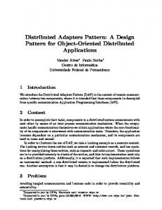
In this section, we define a new specific real-time design pattern, entitled ADAS Action Subsystem (ADAS-AS), designed to model the architecture of ADAS actuators and HMI elements. The definition of the appropriate solution, in terms of static and dynamic views, is based on the process development described in the Section IV. In order to describe common and variable parts that must be present in the pattern, we begin to study and model three commercial ADAS systems among the systems which we have modeled. These systems are: Lateral Safe (LS) system that is representative of lateral control systems, Adaptive Cruise Control (ACC) system that is representative of longitudinal control systems and Saferider system that is representative of longitudinal and lateral control systems. These applications are designed by professors who have an experience in UML based on the study several documents provided by the automotive companies [5][1][24]. A. Description of ADAS systems 1) Lateral Safe system (LS): LS [5] is a system that reduces the risk of collisions in lateral and rear area of the vehicles. In addition, this system assists the driver in adverse or low visibility conditions. LS system warns the driver by using an effective HMI. This HMI has been evaluated and demonstrated in VOLVO cars [5]. LS system consists of several HMI elements: (i) The side and rear view mirrors HMI with leds which are activated in different colors and number, related to the danger level (e.g., cautionary and imminent warnings), (ii) the a-pillar with a symbol light, activated to warn the driver of the risk of a critical lateral collision and (iii) the car speaker, providing directional acoustical warnings in the case of imminent lateral collisions. The time warning depends on speed and driver reaction time and is presented to driver few times before the hazard using two warning levels (imminent danger and cautionary danger). The warnings are provided for a period with priority during each critical situation in order to reduce the number of false alarms. The HMI devices are activated via the HMI manager for each received action signals. Figure 1 shows the class diagram which represents the HMI of LS system. This class diagram is resulted from the study of several documents provided by the automotive companies [5]. This model represents the following classes: (a) HMIElement class that contains the main properties of the HMI elements included in the lateral safe system; (b) CarSpeaker and LEDDevice that represent the subclasses of HMIElement generic class; (c) HMIManager class that activates the HMI warning elements; (d) WarningSignalType class that represents the type of warning provided by the HMI elements; (e) BeepSound and LightSymbol that represent subclasses of WarningSignalType class; (f) WarningSignal class that concerns the warnings delivred to the driver in critical situations; (g) Driver class that is associated with WarningSignal class to indicate that the driver will be warned in critical situations; (h) Vehicle class that is associated with Driver class to indicate that the driver has changed the status of the controlled vehicle taking into account
Copyright (c) IARIA, 2013.
ISBN: 978-1-61208-304-9
the generated alert; (i) DriverAction class that represents the driver’s reactions to the warning in order to avoid accidents. Figure 2 shows the sequence diagram which represents the dynamic aspect of the action subsystem of LS system. 2) Adaptive Cruise Control system (ACC): ACC system is an automotive application that is integrated and tested in modern luxury cars such as BMW [1]. ACC system aims at reducing the risk of accidents and providing safety and comfort to drivers and vehicles by adapting the vehicle’s speed to the traffic environment. This system allows also keeping safe distance between the ACC-vehicle and the forward vehicle. The controller reads sensor data and calculates the desired acceleration or deceleration to maintain the safe distance. Then, it sends the corresponding values to the brake actuator or the throttle actuator. If a preceding slower vehicle is detected, ACC will decelerate the vehicle by applying the brakes (activate brake actuator) without driver application of the brake pedal to maintain a safe distance. In the absence of a preceding vehicle, ACC will accelerate the vehicle back to its set cruise control speed by activating the throttle actuator. In the case where braking is insufficient to maintain the safety distance, ACC will generate a light symbol and an audible distance alert if the intervention by the driver is needed to keep the safe distance. Figure 3 shows the class diagram of the action subsystem of ACC system. This diagram represents the following classes: (a) AutomaticActuator class that contains the main properties of the automatic actuators of ACC system. AutomaticActuator class concerns each device in a car that executes some kinds of automated mechanical actions such as brake and throttle devices, (b) DashboardDisplay that includes the main properties of the HMI element, (c) BrakeActuator and ThrottleActuator that represent the subclasses of AutomaticActuator generic class, (d) AutomaticAction class that models the actions triggered by automatic actuators; (e) InterfaceActuator class that properly activates the HMI components or the mechanical actuators; (f) WarningAlarm class; (g) WarningSignalType class that constitutes the type of signals; (h) BeepAlert and SymbolLight that represent subclasses of WarningSignalType class; (i) Driver class and CorrectiveAction class; (j) Car class that is associated with Driver and CorrectiveAction classes to indicate that the driver modifies the status of the vehicle taking into account the warning signal. Besides, Car class is associated with AutomaticAction class to indicate that the status of the vehicle can be updated by activating the brake or the throttle actuators. Figure 4 presents the sequence diagram of the actuators and the HMI elements of ACC system to model the interactions between the components of the action subsystem. 3) Saferider system: Saferider system (www.saferidereu.org) is an advanced telematics for enhancing the safety and comfort of motorcycle riders [24]. It consists of the following functions: (a) speed alert that alerts the rider when the speed exceeds the legal speed limits, (b) curve speed warning that alerts the rider when his/her speed is too high into a curve, (c) frontal collision warning that warns the rider when an obstacle is detected in front of the motorcycle and (d) intersection support that alerts the rider when a danger is present in intersections. These functions are based on the comparison between
155
ICSEA 2013 : The Eighth International Conference on Software Engineering Advances
Fig. 1.
Fig. 2.
Fig. 3.
Class diagram of the action subsystem of LS system.
Sequence diagram of the action subsystem of LS system.
Class diagram of the action subsystem of ACC system.
the actual rider manœuvre and the safe reference manœuvre which is calculated based on both the motorcycle’s dynamics and the road characteristics. Once a hazard is detected, the warnings are generated through the following HMI elements which are activated using the HMI manager: (i) Head Up display integrated in the helmet, dashboard display and visual attractor on rear mirror providing visual warnings, (ii) inhelmet speakers providing audio warnings (e.g., acoustic and speech messages), (iii) haptic seat, haptic throttle, haptic golve
Copyright (c) IARIA, 2013.
ISBN: 978-1-61208-304-9
and haptic handle providing haptic warnings (i.e., vibration). The HMI elements have been tested and demonstrated on the Yamaha and the Piaggio [24][25]. Figure 5 and Figure 6 illustrate, respectively, the class diagram and the sequence diagram of the HMI of Saferider system.
We note that the common elements are represented with a bold lines in Figures 1, 3 and 5.
156
ICSEA 2013 : The Eighth International Conference on Software Engineering Advances
Fig. 4.
Sequence diagram of the action subsystem of ACC system.
Fig. 5.
Class diagram of the action subsystem of Saferider system.
Fig. 6.
Sequence diagram of the action subsystem of Saferider system.
B. Application of rules to define ADAS-AS pattern We note similarities and differences between LS system, ACC system and Saferider system. The identification of these similarities and differences allows us designing the pattern class and sequence diagrams. The design of our pattern class diagram is based on applying the unification rules as shown in the following:
Copyright (c) IARIA, 2013.
ISBN: 978-1-61208-304-9
•
The following elements are equivalent: ◦ ◦ ◦
HMIElement (LS), DashboardDispaly (ACC) and HMIDevice (Saferider). HMIManager (LS), InterfaceActuator (ACC) and HMIManager (Saferider). Vehicle (LS), Car (ACC) and Motorcycle (Saferider).
157
ICSEA 2013 : The Eighth International Conference on Software Engineering Advances
◦
Driver (LS), Driver (ACC) and Rider (Saferider). ◦ WarningSignal (LS), WarningAlarm (ACC) and WarningSignal (Saferider). ◦ WarningSignalType (LS), WarningSignalType (ACC) and WarningModality (Saferider). HMIElement, Vehicle, Manager, Driver, WarningSignal and WarningSignalType classes are added to the pattern as fundamental classes and they are stereotyped >. •
•
•
•
Visual, audio and haptic warnings (N var(BeepSound (LS), LightSymbol (LS), VisualWarning (Saferider), StereoAudio (Saferider), HapticWarning (Saferider), BeepAlert (ACC), SymbolLight (ACC)) [23]) are variable elements (i.e., represented with specialization relationships). Thus, VisualWarning, AudioWarning and HapticWarning are added as optional classes and they are stereotyped >. AutomaticAction and AutomaticActuator classes are present in ACC system and in other modeled systems which exist in the literature. Thus, AutomaticAction and AutomaticActuator are added to the pattern as optianl classes and they are stereotyped >. LEDDevice, CarSpeaker, ThrottleActuator, BrakeActuator, VisualDevice, VisualDisplay, HeadUpDisplay, VisualAttractor, InHelmetSpeaker, HapticDevice, HapticThrottle, HapticHandle, HapticSeat and HapticGolve are specific classes for each application. Thus, they are not added in the pattern. Once the classes are added to the pattern, we define the relations between classes. For example, the system provides warnings to the driver in critical situations. Thus, it exists a relation between Driver and WarningSignal classes. That is, Driver class is associated with the WarningSignal class. Driver and WarningSignal are mandatory classes, thus the association between them is added to the pattern as a fundamental relation which is stereotyped >.
sequence diagram as an optional element and it is seterotyped >. •
The following messages are equivalent: ◦ GenerateWarning() (LS), DisplayWarning() (ACC), ProvideWarning() (Saferider). ◦ TakeAction() (LS), TakeAction() (ACC), TookCorrectiveAction() (Saferider). ◦ UpdateState() (LS), UpdateState() (ACC), UpdateState() (Saferider). Rule RS-4 is applied by adding GenerateWarning(), TakeAction() and UpdateState() messages to the sequence diagram as fundamental elements.
•
ExecuteAction() is present in ACC system and other modeled systems. It exists between InterfaceActuator and AutomaticActuator. Rule RS-6 is applied. ExecuteAction() message is added to the pattern sequence diagram as an optional message and it is stereotyped >.
VI.
In this section, we describe the proposed pattern through the following elements: name, context, problem, forces and solution. 1) 2)
3)
4)
The design of our pattern sequence diagram is based on the application of the unification rules (Section IV), as shown in the following: •
•
The following elements are equivalent: ◦ HMIManger (LS), InterfaceActuator (ACC), HMIManager (Saferider). ◦ HMIElement (LS), DashboardDisplay (ACC), HMIDevice (Saferider). ◦ Driver (LS), Driver (ACC), Rider (Saferider). ◦ Vehicle (LS), Car (ACC), Motorcycle (Saferider). Rule RS-1 is applied by adding the following lifelines: Manager, HMIElement, Driver and Vehicle to the pattern sequence diagram as fundamental elements and they are stereotyped >. AutomaticActuator lifeline is present in several applications (ACC and other modeled systems). Rule RS-2 is applied by adding this lifeline to the pattern
Copyright (c) IARIA, 2013.
ISBN: 978-1-61208-304-9
D ESCRIPTION OF ADAS ACTION S UBSYSTEM PATTERN
5)
Name ADAS Action Subsystem (ADAS-AS). Context When the system detects a critical situation, it generates warning information to the driver through an HMI and/or it provides automatic actions (e.g., activates the brake actuator or the throttle actuator). Problem How ADAS-AS can be applied to take the actions (automatic actions and/or warning information) that increase the driver’s safety and prevent collisions? Forces The action subsystem communicates the warnings to the driver through an appropriate HMI (visual, audible and haptic devices) and/or activates vehicle dynamic actuators (e.g., steering and brakes) according to a potential risk. Driver will be warned early of hazards using different warning levels (e.g., low danger and high danger) to have enough time to take a corrective action. In fact, the warning time depends on the reaction time of each driver. Solution Static specification: Figure 7 presents the action subsystem static view, i.e., the participants represented by the class diagram. AutomaticActuator. The modeled actuators are devices in a vehicle, used to generate automatic mechanical actions such as brakes actuators which make the vehicle go slow or stop. AutomaticActuator class has: (i) Status attribute that represents the state’s actuator (i.e., an actuator can be activated or deactivated) and (ii) ReactionTime attribute that represents the time needed for an actuator to provide automatic actions. This class has an ExecuteAction() operation to indicate that the actuator makes an
158
ICSEA 2013 : The Eighth International Conference on Software Engineering Advances
Fig. 7.
Fig. 8.
ADAS-AS pattern.
Action subsystem sequence diagram.
automatic force to change the vehicle’s state, and thus reduces the risk of accidents. This operation is stereotyped > to indicate that the action is performed whenever a critical situation is detected. We define an OCL constraint related to the AutomaticActuator class. This constraint (context AutomaticActuator::ExecuteAction() pre: deadline ≤ current time + D), where D is the duration before a risk occurs. HMIElement. The modeled HMI elements are devices that provide warning information to the driver. They can be a car speaker, a Head-Up Display and
Copyright (c) IARIA, 2013.
ISBN: 978-1-61208-304-9
a haptic seat. HMIElement class has: (i) Location attribute that represents the position of the HMI element in the vehicle, (ii) Status attribute that represents the state’s HMI and (iii) RateFA attribute that represents a needless alarm given by a processing error. This Class has a GenerateWarning() operation to indicate that an HMI element provides warnings to the driver in order to react. This operation is stereotyped > because an HMI element generates warning information only if a danger is detected. We define an OCL constraint related to the HMIElement class. This constraint (context HMIEle-
159
ICSEA 2013 : The Eighth International Conference on Software Engineering Advances
ment::GenerateWarning() pre: deadline ≤ current time + D + self.Driver.ReactionTime), where D is the duration before a risk occurs. The HMI element generates warnings taking into account the driver’s reaction time. Manager. The manager is responsible for processing the warning provided by the controller. It indicates which HMI hardware components or automatic actuators should be active/inactive. AutomaticAction. This class represents the different actions provided by an automatic actuator to avoid dangers (e.g., automatic braking). WarningSignal. The action subsystem provides different warnings if a critical situation is detected. These warnings are generated to the driver through HMI elements. WarningSignalType. The warning signals are classified into visual, auditory and haptic modes. These types are characterized by (i) a priority that represents the level of the warning according to the degree of hazard (e.g., high warning and low warning). The high priority warning requires an immediate action and should be distinguishable from other warnings, (ii) a duration that constitutes the time interval in which the warning is considered valid and (iii) repetition that represents the repetition rate of the warning. AudioWarning. Auditory warnings include both acoustic (e.g., tone and auditory icons) and speech outputs. These warnings should be presented in higher frequency. VisualWarning. Visual outputs can be symbols and/or texts. These warnings should take into account some properties such as luminance, size, flashing rate and color. HapticWarning. Haptic warnings should be sufficiently intense to make drivers able to feel them. They should be presented in a form that the driver is physically able to perceive them (e.g., steering wheel vibration and accelerator vibration). Driver. The driver needs to understand the warning signal, to choose an appropriate response and to take action. The driver must react immediately to reduce the risk of accident. This class has TakeAction() operation which is stereotyped > to indicate that the driver take a corrective action only if the system generates warnings. DriverAction. This class represents the reactions taken by the driver after each warning of a hazard event, such as braking and steering. We use notes to define a constraint under OCL (Object Constraint Language) related to the DriverAction class. This constraint (context DriverAction inv: self.Duration ≤ self.WarningSignalType.Duration) indicates that the driver must react immediately. Vehicle. This class has the UpdateState() operation to indicate that the vehicle changes its status according to any automatic action provided by a mechanical actuator (represented by the association between Vehicle class and AutomaticAction class) or any action taken by the driver (represented by the association between Vehicle class and DriverAction class). Dynamic specification: Figure 8 presents a sequence
Copyright (c) IARIA, 2013.
ISBN: 978-1-61208-304-9
diagram of the action subsystem pattern. In this diagram, we are interested in modeling the manner to take an action that minimizes the hazards and prevents accidents. In fact, the action subsystem consists of (i) several automatic actuators which provide some automated actions through the ExecuteAction() operation such as the brake actuator which activates the brake pedal to decelerate the vehicle, and (ii) different HMI elements which deliver warnings to the driver through the GenerateWarning() operation. The driver takes the appropriate decision according to the generated warning through the TakeAction() operation. For example, if a system detects a risk of frontal collision, it provides warnings indicating that the driver must decelerate to avoid the collision. When the action (automatic action or warning) is taken, the controlled vehicle updates its state through the UpdateState() operation. ExecuteAction(), GenerateWarning(), TakeAction() and UpdateState() operations are stereotyped > to indicate that the actions are triggered only if the system detects an hazard. VII.
C ONCLUSION AND FUTURE WORK
The main objective of this work was to define a RT design pattern specific to the action subsystem of ADAS. This pattern, named ADAS-AS, models the structural, behavioral and real time aspects of an action subsystem. In fact, it models the different components of the actuator subsystem of ADAS such as the automatic actuators and the HMI elements. This pattern facilitates the modeling of any ADAS; it will be easy for the designer to reuse this pattern by adapting it to the needs of a particular advanced driver assistance system without starting from scratch. Therefore, modeling using ADAS-AS reduces the system failure. However, using another pattern such as [6][10][16] allows the designer to add all specificities of an ADAS. So, the developed system does not meet the requirements. In future work, we will propose to reuse the following patterns to model real industrial ADAS systems: the data acquisition pattern proposed in [9], the controller pattern defined in [10] and the ADAS-AS pattern defined in this paper. We will propose also to develop a tool that supports the definition of ADAS patterns and the dictionary of the semantic relations in the design process. Then, we will propose an approach of using patterns to build a new architecture of an ADAS system that integrates a RT database. This approach helps designers to build their systems without starting from scratch. The developer is limited to provide the properties and the specificities related to a particular system. R EFERENCES [1]
W. Prestl, T. Sauer, J. Steinle, and O. Tschernoster, ”The BMW active cruise control ACC,” SAE transactions, vol. 109, no. 7, 2000, pp. 119125, doi:10.4271/2000-01-0344. [2] E. Johansson, E. Karlsson, C. Larsson, and L. Eriksson, ”Implementation and evaluation of lane departure warning and assistance systems,” Advances in Human Aspects of Road and Rail Transportation, Edited by Neville A . Stanton, 2012, pp. 37-46.
160
ICSEA 2013 : The Eighth International Conference on Software Engineering Advances
[3]
[4]
[5]
[6]
[7]
[8] [9]
[10]
[11]
[12]
[13]
[14]
[15]
[16]
[17] [18] [19]
[20] [21] [22]
M. R. Ghahroudi and R. Sabzevari, ”Sensor data and fusion,” Vienna, Austria: I-Tech Education and Publishing KG, ch. Multisensor Data Fusion Strategies for Advanced Driver Assistance Systems, 2009, pp. 141-166. F. Biral, M. D. Lio, R. Lot, and R. Sartori, ”An intelligent curve warning system for powered two wheel vehicles,” European Transport Research Review, vol. 2, no. 3, Dec. 2010, pp. 147-156. L. Danielsson, H. Lind, E. Bekiaris, M. Gemou, A. Amditis, M. Miglietta, and P. St˚alberg, ”HMI principles for lateral safe applications,” in Universal Access in Human-Computer Interaction, ser. Lecture Notes in Computer Science, C. Stephanidis, Ed. Springer-Verlag Berlin, Heidelberg, vol. 4555, July. 2007, pp. 330-338. E. Gamma, R. Helm, R. Johnson, and J. Vlissides, ”Design patterns: Elements of Reusable Object-Oriented Software,” Addison-Wesley Edition, 1994. A. Armoush, F. Salewski, and S. Kowalewski, ”Design pattern representation for safety-critical embedded systems,” Journal of Software Engineering and Applications, vol. 2, April. 2009, pp. 1-12. P. D. Bruce, ”Real-Time Design Patterns: Robust Scalable Architecture for Real-Time Systems”, Addison-Wesley Edition, 2002. H. Marouane, A. Makni, R. Bouaziz, C. Duvallet, and B. Sadeg, ”A real-time design pattern for advanced driver assistance systems,” in Proceedings of 17th European conference on Pattern Languages of Programs (EuroPLoP 2012), 2012, pp. C6:1-C6:11. S. Rekhis, N. Bouassida, C. Duvallet, R. Bouaziz, and B. Sadeg, ”A UML-profile for domain specific patterns: Application to real-time,” in DE@CAISE’10: the Domain Engineering workshop of the 22nd International Conference on Advanced Information Systems Engineering (CAiSE’10), Hammamet, Tunisia, 2010, pp. 32-46 S. Rekhis, N. Bouassida, C. Duvallet, R. Bouaziz, and B. Sadeg, ”A Process to Derive Domain-Specific Patterns: Application to the Real-Time Domain,” Proceedings of 14th International Conference on Advances in Databases and Information Systems (ADBIS’2010), Sept. 2010, pp. 475-489. S. Rekhis, N. Bouassida, C. Duvallet, R. Bouaziz, and B. Sadeg, ”Modeling real-time applications with reusable design patterns,” International Journal of Advanced Science and Technology (IJAST), vol. 22, 2010, pp. 71-86. D. C. Schmidt, M. Stal, H. Rohnert, and F. Buschmann, ”PatternOriented Software Architecture: Patterns for Concurrent and Networked Objects,” 2n d ed. New York, NY, USA: John Wiley Sons, Inc., 2000. D. Slutej, J. Hakansson, J. Suryadevara, C. Seceleanu, and P. Pettersson, ”Analyzing a pattern-based model of a real-time turntable system,” in 6th International Workshop on Formal Engineering approaches to Software Components and Architectures(FESCA), ETAPS’09, York, UK, B. Z. Jens Happe, Ed., Electronic Notes in Theoretical Computer Science (ENTCS), Elsevier, vol. 253, Oct. 2009, pp. 161-178. K. Soundararajan and R. W. Brennan, ”Design patterns for realtime distributed control system benchmarking,” Journal of Robotics and Computer-Integrated Manufacturing, vol. 24, no. 5, Oct. 2008, pp. 606615. S. Konrad and B. H.C. Cheng, ”Requirements Patterns for Embedded Systems,” Proceedings of the IEEE Joint International Conference on Requirements Engineering (RE02), Sept. 2002, pp. 127-136. OMG, ”Unified modeling language (UML) infrastructure,” v2.1.2, formal/2007-11-04, 2007. M. Clauß and I. Jena, ”Modeling variability with UML,” in In GCSE 2001 Young Researchers Workshop, 2001. N. Idoudi, C. Duvallet, R. Bouaziz, B. Sadeg, and F. Gargouri, ”Structural model for real-time databases: an illustration,” in Proceedings of 11th IEEE International Symposium on Object-oriented Real-time distributed Computing (IEEE ISORC’2008). Orlando, United States: IEEE Computer Society Washington, May. 2008, pp. 58-65. OMG, ”A UML profile for MARTE,” 2007. OMG, ”UML 2.0 OCL specification,” 2007. K. K. Aggarwal, Y. Singh, A. Kaur, and R. Malhotra, ”Software reuse metrics for object-oriented systems,” in Proceedings of the third ACIS International Conference on Software Engineering Research, Management and Applications (SERA’05). IEEE computer society, Aug. 2005, pp. 48-54.
Copyright (c) IARIA, 2013.
ISBN: 978-1-61208-304-9
[23]
N. Bouassida, H. Ben-Abdallah, F. Gargouri, and A. Ben-Hamadou, ”A stepwise framework design process,” in IEEE International Conference on Systems Man and Cybernetics, Hammamet, Tunisia, 2002. [24] E. D. Bekiaris, A. Spadoni, and S. I. Nikolaou, ”Saferider project: new safety and comfort in powered two wheelers,” in Proceedings of the 2nd conference on Human System Interactions. Piscataway, NJ, USA: IEE press, May. 2009, pp. 600-602, doi: 10.1109/HSI.2009.5091045. [25] J. P. Diederichs, M. Fontana, G. Bencini, S. Nikolaou, R. Montanari, A. Spadoni, H. Widlroither, and N. Baldanzini, ”New HMI concept for motorcycles - the saferider approach,” in Proceedings of the 8th International Conference on Engineering Psychology and Cognitive Ergonomics: Held as Part of HCI International 2009. Springer-Verlag Berlin, Heidelberg, July 2009, pp. 358-366.
161