A Real Time Gesture Recognition System for Mobile Robots - CiteSeerX
Recommend Documents
This hand gesture recognition technique aims to substitute the use of mouse for interaction with the virtual objects. This will be useful to promote controlling ...
International Journal of UbiComp (IJU), Vol.3, No.1, January 2012 ... This hand gesture recognition technique aims to substitute the use of mouse for interaction ...
May 8, 2012 - interaction with 3D objects. The 2 degrees of ... application in gallery browsing 3D depth data analysis method. ..... in implementations of Tetris.
Mixture Model (GMM) over YCbCr color space. In the second step, the hand is localized and tracked by using a blob analysis for hand region. 2.1.1 Skin Color ...
Our application uses images from a low-cost web camera placed in front of the .... In order to make the application robust to these segmentation errors we add a .... characteristics for the hand shape can be derived like the depth average, d ,. â.
“Mobile Robot Design apply to Design Concept”. SICE-ICASE International Joint Conference 2006 Oct. 18-2 1, 2006 in Bexco, Busan, Korea. [13]: UCN5084B ...
Ahmad 'Athif Mohd Faudzi*, Muaammar Hadi Kuzman Ali, M. Asyraf Azman, Zool Hilmi. Ismail. aDepartment of Mechatronics and Robotics Engineering, Faculty ...
Keywords - hand detection, hand recognition, segmentation, skin color. I. INTRODUCTION ..... Particle Filter" 2012. International Workshop on Information and.
Keywords: Hand Gesture Recognition; Human Computer Interface; FPGA. ... Various hand gesture recognition algorithms have been developed by researchers ...
interaction with Desktop/Laptop with static hand gesture. All these techniques were using real time approach with different feature descriptors such as Fourier ...
tracking, active learning, bootstrap, Adaboost, nested cascade classifiers. .... As already mentioned, once the tracking module is correctly following a hand,.
Vienna Univ. of Technology. Vienna Univ. of ... important role in many technical applications. In this ... robots have enough battery resources and space available to allow the use .... voltage of 0.8 â 1.2 Volt dependent upon the clock, it require
with intensive graphics rendering workloads are unable to run on mobile platforms ... Rv i. Rv+ j. Sj. Iv+âv+ j. Client. Server. Fig. 1. The framework of a remote ...
Circles generated using Bresenham's algorithm were employed for finding corners as ... Hand gesture recognition plays an important role in the following areas:.
... 2012, 3, 364-367 http://dx.doi.org/10.4236/jsip.2012.33047 Published Online August 2012 (http://www. ... Sign Language (ASL) in Complex Background. Jayashree R. ..... on Digital Image Processing, Bangkok, 7-9 March 2009, pp. 284-287.
Fels' Glove Talk [3] focused on a gesture-to-speech interface. Moreover, a multilayer perceptron model was used in Beale and Edwards' posture recognizer [1] ...
canter, tracking the hands trajectory and analyzing the variations in the hand locations, .... direction extents, then increment given angle and add the distance.
Jun 5, 2016 - AbstractâThe objective of this work is to develop a real-time gesture prediction .... Android application was developed. In the application, user ...
board which consists of a dual-core ARM Cortex A9 CPU and a Nvidia mobile GPU .... Android. Fig. 2. Tegra development board and the experimental setup.
Choudhury A. Rahman, Wael Badawy. Department of Electrical and Computer Engineering. University of Calgary. Calgary, Alberta, Canada T2N 1N4. {rahmanc ...
A smart and simple algorithm is presented in this paper for vehicle's license plate recognition system. Based on pattern matching, this algorithm can be applied.
POLAROID Corporation, 1989, Ultrasonic Components. Group, 119 Windsor Street, Cambridge, MA, 02139. Raschke, U. and Borenstein, J., "A Comparisson of ...
A Real Time Gesture Recognition System for Mobile Robots - CiteSeerX
This paper presents a vision system to be embedded in a mobile robot, both of them implemented using recon- ... processing custom chips (Zemcik, 2002).
A Real Time Gesture Recognition System for Mobile Robots Vanderlei Bonato1 , Adriano K. Sanches1 , M.M. Fernandes2 Jo˜ao M. P. Cardoso3 , E. D. V. Simoes1 , Eduardo Marques1 1
Institute of Mathematics and Computing Sciences, University of S˜ao Paulo
S˜ao Carlos, Brasil {vbonato,aks,simoes,emarques}@icmc.usp.br 2
University Metodista of Piracicaba - UNIMEP; Piracicaba, S˜ao Paulo
This paper presents a vision system to be embedded in a mobile robot, both of them implemented using reconfigurable computing technology. The vision system captures gestures by means of a digital color camera, and then performs some pre-processing steps in order to use the image as input to a RAM-based neural network. The set of recognized gestures can be defined using the system on-chip training capabilities. All the above functionality has been implemented in a single FPGA chip. Experimental results have shown the system to be robust, with enough performance to meet real-time constraints (30 fps), and also high efficiency in the recognition process (true recognition rate of 99.57%).
1
INTRODUCTION
Mobile robots have been the central focus of many research works in recent years, dealing with the uncertainty associated with the environment and the data received via sensors. In this context, machine learning and probabilistic models are important advances able to deal with the computational complexity involved (Thrun et al., 2000). Specialized hardware is an attractive solution to implement robots with real-time constrains. The use of FPGAs (Field-Programmable Gate Arrays) is a flexible alternative to implement complex models, as the hardware functionality can be changed according to the task to be executed (Oldfield, 1995). It can also be argued that FPGAs are able to execute image processing algorithms with speed comparable to graphics processing custom chips (Zemcik, 2002). However, designing and programming such a specialized hardware can still be very complex, which has motivated us to propose a tool for the design of reconfigurable robots (Gonc¸alves et al., 2001) (Gonc¸alves et al., 2003). The approach needs modular hardware units that are then allocated at the exact time they are needed. The hardware generated is based on softcores and special purpose RPUs (Reconfigurable Processing Units), as seen in Figure 1. A softcore is a processor core described in a hardware description lan-
guage. The software image to be executed might include invocations to RPU functionalities. The RPUs are stored in a library of functional units (RPUs repository), and can be organized in a way that best suits a given application. The RPUs can be manually designed hardware units or architectures to implement specific computational structures, obtained using an architectural synthesis tool (Cardoso and Neto, 2003). This paper presents the design and implementation of an RPU for real time gestures recognition, which can be used as a human-robot communication interface. By doing so it is possible to interact with a robot in a non-conventional way, which could be useful in particular situations (e.g. robots designed to assist disabled people). This gesture recognition unit will be incorporated to the tool presented above, and could be used not only to recognize gestures, but also as a basis for other applications requiring image patterns recognition. The structure of the main modules of the robot currently being developed is shown in Figure 2, along with the interactions among them. The vision processing module corresponds to the RPU presented in this paper. This paper is organized as follows. Section 2 explains the robot vision system and its components. Section 3 explains the neural network for gesture recognition, and Section 4 shows the experimental results obtained. Finally, section 5 concludes this paper.
Figure 2: Integration of the vision system into the robot architecture
2
Source Code Statistical Data for a New (Better) Configuration Compiler Front-End (GNU PRO) Intermediate Representation
LEGUS System
VHDL/ Verilog
Compiler Back-End (GNU PRO)
RPUs Repository
Object Code
Logic Synthesis for FPGA (Quartus II)
Netlist NIOS Processor
RPUs
Embedded Operating System (eCos or UClinux) Stratix FPGA
Placement and Routing (Quartus II)
Reconfiguration Bitstream
Figure 1: A tool for robot design
A ROBOT VISION SYSTEM
Computer vision systems for human-robot interaction have evolved significantly in the past decade. However, most of them are not robust yet, have low performance, and so are not suitable to be used in embedded systems with real time constraints (Turk, 2004). Most of the previous work in this area delivers the right functionality (Waldherr et al., 2000), but not as an embedded device. The system presented in this paper seeks to address this issue. The structure of the vision system is shown in the blocks diagram of Figure 3. The structure consists of a pipeline of functional blocks for image processing operations, which are executed in parallel. The system is implemented as a SoC, which allows the gestures recognition system to operate in real time. Each of those blocks is responsible for an image processing step, such as image capturing, RGB to HSI color conversion, image segmentation, image filtering and compression, and finally the centering of the image. These pre-processing steps are performed prior to the actual neural network gesture recognition (shown in section 3). The integration of the vision system to the robot is done by means of two communication buses: the configuration bus, used to configure FPGA structures, and the data bus used to send the interpreted gestures to the robot control module. In the next subsections we describe in more details the image pre-processing steps of the vision system.
2.1
Image Capturing
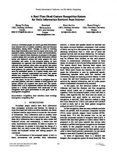
The images used by the gestures recognition system are captured by a C3188A digital camera, which uses
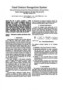
The R, G, B values and address of each pixel are then sent to the following block of the system, which converts the RGB color scheme into HSI. The interpretation of pixels is performed in real time. As an example, Figure 5 shows an RGB image representing the ”GO” gesture. This and other images presented have been generated by the FPGA hardware implementation described in this paper. In order to capture those images, an Ethernet based communication system between the system a PC has been implemented. In addition to capturing images, the interface also served as a debugging interface.
FPGA
Figure 3: Vision system blocks diagram
an ov7620 CMOS image sensor (Electronics, 2004). This kind of sensor integrates all the functionalities of a digital camera in a single integrated circuit, allowing for reduced size, low cost, and low power consumption (Rowe, 2002). Those are important parameters for the design and implementation of mobile autonomous robots. The camera is able to sustain a rate of imagens equals to 30 frames per second (fps). The resolution of gray shade images is 640x480 pixels, while RGB color images have a resolution of 320x240 pixels. That camera is shown in Figure 4.
Figure 4: CMOS C3188A Camera - 1/3”
The camera configuration is done through the image sensor by using the communication protocol I2 C (Philips, 2003). The configuration parameters are stored in a register set, which can be read or written through a communication port. Several parameters can be configured, like fps rate, noise compensation, and image saturation, among others. In our vision system the configuration is done via the Camera Control block (Figure 3).
2.2
Pixels Reading
The data sent by the camera are interpreted by the Pixel Read block (Figure 3). The data are sent through a 16-bit bus, containing information about the R,G, and B values of each pixel, and also synchronization signals. Based in these, the block reads the pixel and associates its address to the image.
Figure 5: RGB (320x240 pixels)
2.3
RGB-HSI Conversion
In this operation the Red, Green, and Blue pixel representation of the RGB scheme are changed into the corresponding HSI representation, which uses the Hue, Saturation, and Intensity componentes. This method is frequently used in image processing systems because the HSI pixel components are independent from each other (as opposed to RGB´s), and so individual operations can be applied to them (Russ, 1995). In addition, the separation of the I component makes the image less sensitive to brightness variations of the working environment. The RGB-HSI conversion can be considered a complex operation in this domain (Gonzalez and Woods, 1992). The complexity of the conversion is due to a trigonometric function that is required to obtain the H value (Equation 1). The implementation of that function in FPGAs demands a significant amount o logical elements to implement the corresponding algorithms. A simplified method to obtain the H component from an RGB representation is presented by Bajon apud Swenson (Swenson, 2002), as shown in Equation 2. This Equation does not use any trigonometric function, and so is simpler to be implemented in hardware. The I and S components can be obtained through Equations 3 and 4, respectively, which are also easily implemented in hardware. Figure 6 shows the H, S, and I values (gray shades) for an RGB image obtained with our vision system.
3
2
H = cos−1 q3
(r − 13 ) − 13 (b − 13 ) − 13 (g − 13 )
2 3 [(r
−
1 2 3)
1 2 3)
+ (b −
+ (g −
1 2 3) ]
(1)
H=
Acromathic g−b
3(r+g−2b) b−r 3(g+b−2r) r−g 3(r+b−2g)
+ +
1 3 2 3
if if if if
r=g=b b = min(r, g, b) r = min(r, g, b) g = min(r, g, b) (2)
I=
r+g+b 3
(3)
S = 1 − 3 ∗ min[r, g, b]
binary values and they are attributed to the f(x,y) position on the segmented image, that correspond to the f(i,j) position. Using the first technique, the result of Equation 5 are the pixels that constitute the segmentated image. In the second technique, the pixels are obtained from a logical AND operation applied to the H, S, and I values resulting from Equation 5. In this work the best results were obtained by using the first technique, therefore it is the one that has been adopted. It should be noticed that the H component depends basically on the skin color of the user interacting with the robot. For this reason, gestures are obtained using the internal part of the hand, as this part of the body has only small variations in color, which helps to avoid further system calibrations. The results of a segmentation operation based on the H value is shown in Figure 7.