Reprinted From: 2007 IEEE Antennas and Propagation Society International Symposium, Honolulu, HI, USA; 9-15 June 2007 Page(s): 3792 – 3795. ©2007 IEEE. Personal use of this material is permitted. However, permission to reprint/republish this material for advertising or promotional purposes or for creating new collective works for resale or redistribution to servers or lists, or to reuse any copyrighted component of this work in other works must be obtained from the IEEE.
SM
A Real-Time Location System Using Near-Field Electromagnetic Ranging Hans G. Schantz The Q-Track Corporation, Huntsville, AL 35816 E-mail:
[email protected] Introduction Near-field electromagnetic ranging (NFER) technology is emerging as a preferred real-time locating system (RTLS) solution for operation in complicated indoor propagation environments [1]. Operating at low frequencies, typically within the AM broadcast band (530-1710kHz), NFER systems exploit the near-field behavior of radio signals within about one-third of a wavelength. This paper explores the performance of NFER systems and the propagation of NFER signals. RTLS with NFER Technology NFER technology relies on some simple but long overlooked physics originally discovered by Heinrich Hertz over a century ago [2]. Close to a small antenna, the electric and magnetic components of a radio wave are ninety degrees out of phase. Far from a small transmit antennas, these components converge to be in phase. By separately detecting, measuring, and comparing the electric and magnetic phases, one obtains a measurement of distance. The relation between range (r) and phase delta (∆φ) is given by:
r=
λ 3
2π
cot ∆φ ,
(1)
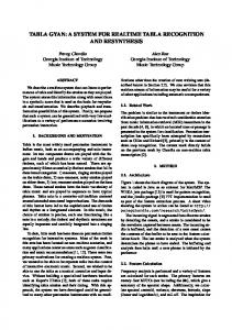
Figure 1 shows how the electric-magnetic phase delta translates to range. A more detailed discussion and derivation is available elsewhere [3]. Range Versus Phase Delta
0.40 Range (Wavelengths)
0.35 0.30 0.25 0.20 0.15 0.10 0.05 0.00 90
75
60
45 30 Phase Delta (deg)
15
0
Figure 1: The phase delta between the electric and magnetic phase components provides useful range information within about one third of a wavelength of an electrically small antenna [© 2006, Q-Track].
Preprint – Submitted to IEEE APS Conference June 2007 ©2007 Q-Track Corporation
In November 2006, Q-Track released the first RTLS solution to exploit NFER technology. Q-Track’s QTTM-400 System includes QTTM-400 Tags, QTTM-400 Locators, and the Exact-TrackTM Software Development Kit. The three-channel QTTM-400 Locator (receiver) is a custom-designed software-controlled doubleconversion radio with a PIC processor. Figure 2a shows a QTTM-400 Tag (transmitter). Figure 2b shows an QTTM-400 Locator. The QTTM-400 system operates in the AM broadcast band under FCC Part 15 power levels (~100mW) at a frequency of 1.3 MHz. Figure 2c shows a screen shot of the QTTM-400 real time tracking graphic user interface (GUI) configured for the display at Q-Track’s Huntsville facility. Receiver locations are denoted by an “RX.” The following section discusses the performance of the QTTM-400 System in more detail
Figure 2a (top-left): A QTTM-400 Tag Transmitter. Figure 2b (top-right): A QTTM-400 Locator Receiver with antenna array. Loopstick and whip antennas enable separate detection of magnetic and electric field components, respectively. Figure 2c (bottom): An Exact-TrackTM-400 GUI displays the location of a mobile transmitter. Accuracy is typically within 30cm (1ft) at ranges up to 70m (230ft) for a calibrated system. [© 2006, Q-Track].
Preprint – Submitted to IEEE APS Conference June 2007 ©2007 Q-Track Corporation
Near-Field Propagation
Far-field signals in links at distances many wavelengths away obey the Friis Law of propagation. For electrically small antennas at distances much less than a wavelength, the Friis Law is no longer valid. In fact, there are two near-field propagation laws [4]. For “like” antenna links (electric-electric or magneticmagnetic), the received power is: PRX ( like ) =
PTX GTX G RX 4
1 1 1 − + (kr )2 (kr )4 (kr )6 ,
(2)
where range is r, the wave number is k = 2π/λ, the transmit power is PTX, and the transmit and receive antenna gains are GTX and GRX, respectively. For “unlike” antenna links (electric-magnetic or magnetic-electric), the received power is: PRX ( unlike ) =
PTX GTX G RX 4
1 1 + (kr )2 (kr )4 .
(3)
In the near field (within λ/2π), like link receive power varies as the inverse sixth power with range (60dB/decade) and unlike link receive power varies as the inverse fourth power with range (40dB/decade). Around λ/2π links converge to the far-field behavior described by the Friis Law and link receive power varies as the inverse square power (20dB/decade). Figure 2 presents this behavior.
Path Gain (dB)
Near Field Channel Model 70 60 50 40 30 20 10 0 -10 -20 -30 0.01
60 dB/ dec ade 40 d B/de cade 20 dB/d ecade
Like Field Unlike Field Far Field
20 dB/ d
ecade
0.1
1 Range (Wavelengths) Figure 3: The near-field channel. In the near-field region (within λ/2π), like links roll-off as the inverse sixth power (60dB/decade) and unlike links roll-off as the inverse fourth power (40dB/decade). In the far-field region, both like and unlike links converge to roll-off as the inverse square power (20dB/decade) described by the usual Friis Law [© 2006, Q-Track].
For Q-Track’s QTTM-400 System, the transmit power is nominally +20dBm, the transmit gain is nominally –75dBi, the electric receive gain is –55dBi, the magnetic receive gain is –55dBi, and the receive bandwidth is about 500Hz. For purposes of characterizing our link, we assume a worst-case night noise scenario with an effective RF noise temperature of 1011K [5]. Figure 4 shows typical
Preprint – Submitted to IEEE APS Conference June 2007 ©2007 Q-Track Corporation
signal-to-noise (SNR) results for Q-Track’s QT-400 Starter Kit system operating at 1.3MHz. Near Field Ranging SNR vs Distance Typical QT-400 Performance
80
SNRH (dB) SNRE (dB)
70 SNR (dB)
60 50 40 30 20 10 0 1
10
Range (m)
100
1000
Figure 4: Typical SNR results for Q-Track’s QT-400 Starter Kit System. [© 2006, Q-Track].
Performance of NFER Systems
The typical performance of the QTTM-400 System is summarized below: • • • • • • • • • •
Range: Frequency dependent, but up to 70m (230ft) at 1.3MHz. Typical ranges in cluttered indoor environments are 30-65m (100-200ft). Scalable to cover any facility. Coverage Area: Three QT™-400 Locators will typically cover an area of at least 930m2 (10,000 sqft), usually more. Accuracy: 1m (3ft) indoors with potential for 30cm (1ft ). Tag Battery: one year at a once/minute update rate. The tag uses 4NiMH AA cells and has a built in battery charger. Update Rate: Better than 10Hz is possible. Operating Frequencies: select frequencies within the AM broadcast band, 530 – 1710kHz. Bandwidth: less than 500Hz. Channelization: The QT™-400 Locator can track more than a dozen QT™-400 Tags. Potentially 1,000’s of tags may be tracked simultaneously. Regulatory: Authorized under FCC Part 15. Transmitter Power: 100mW (maximum allowed under FCC Part 15.219 regulations).
References: [1] Hans Schantz and Robert DePierre, “System and method for near-field electromagnetic ranging,” US Patent 6,963,301, November 8, 2005. “NFER” is a registered trademark of the Q-Track Corporation. For additional information please see www.q-track.com. [2] Heinrich Hertz, Electric Waves: Being Researches on the Propagation of Electric Action with Finite Velocity Through Space, London: Macmillan & Co., 1893, p. 152. [3] Hans Schantz, "Near-Field Phase Behavior," 2005 IEEE Antenna and Propagation Society International Symposium, 3-8 July 2005, Vol. 3B, pp. 134-137. [4] Hans Schantz, “A Near-Field Propagation Law & A Novel Fundamental Limit to Antenna Gain Versus Size,” 2005 IEEE Antenna and Propagation Society International Symposium, 38 July 2005, Vol. 3A, pp. 237-240. [5] Robert E. Collin, Antennas and Radiowave Propagation, New York: McGraw Hill, 1985, p. 324.