16 No.1, 2012 pp.15-25. ISSN 1405- ... instruction decode, IR instruction rename, IDi instruction ... guarantees it by reserving the number of stages equal to the ...
A Reorder Buffer Design for High Performance Processors José R. García Ordaz, Marco A. Ramírez Salinas, Luis A. Villa Vargas, Herón Molina Lozano, and Cuauhtémoc Peredo Macías Microtechnology and Embedded System Laboratory, Centro de Investigación en Computación, Instituto Politécnico Nacional, Av. Juan de Dios Bátiz, s/n, Zacatenco, 07738, México DF, Mexico jgarcia, mars, lvilla, hmolina, cperedo@cic.ipn.mx Abstract. Modern reorder buffers (ROBs) were conceived to improve processor performance by allowing instruction execution out of the original program order and run ahead of sequential instruction code exploiting existing instruction level parallelism (ILP). The ROB is a functional structure of a processor execution engine that supports speculative execution, physical register recycling, and precise exception recovering. Traditionally, the ROB is considered as a monolithic circular buffer with incoming instructions at the tail pointer after the decoding stage and completing instructions at the head pointer after the commitment stage. The latter stage verifies instructions that have been dispatched, issued, executed, and are not completed speculatively. This paper presents a design of distributed reorder buffer microarchitecture by using small structures near building blocks which work together, using the same tail and head pointer values on all structures for synchronization. The reduction of area, and therefore, the reduction of power and delay make this design suitable for both embedded and high performance microprocessors. Keywords. Superscalar processors, reorder-buffer, instruction window, low power consumption.
Diseño de un búfer de reordenamiento para procesadores de alto desempeño Resumen. El búfer de reordenamiento de instrucciones (ROB) fue conceptualizado para mejorar el desempeño de los procesadores al permitir ejecutar instrucciones fuera del orden original del programa y en avance al instante preciso de la ejecución secuencial, explotando el paralelismo que existe a nivel de las instrucciones ILP. El ROB es una estructura funcional de la máquina de ejecución de los procesadores para dar soporte a la ejecución especulativa, al reciclado de los registros físicos y a la recuperación precisa de excepciones. Tradicionalmente el ROB es considerado un búfer
circular monolítico en donde las instrucciones entran en la dirección especificada por un apuntador de cola después de la etapa de decodificación y son terminadas en la dirección especificada por un apuntador de cabecera después de la etapa de finalización. El artículo presenta el diseño de un búfer de reordenamiento de instrucciones distribuido en pequeñas estructuras cercanas a los bloques funcionales con los cuales interactúan, usando los mismos valores de apuntadores de cola y cabecera por sincronía. La reducción de área y por consecuencia la reducción de consumo de energía y retardo hacen de este diseño apropiado para procesadores embebidos y procesadores de alto desempeño. Palabras Clave. Procesadores súper escalares, búfer de reordenamiento, ventana de instrucciones, consumo de baja potencia.
1 Introduction Superscalar processors allow the execution of more than one instruction in a clock cycle; this goal becomes increasingly complex to achieve in hardware. The total complexity is distributed along the pipeline stages in order to make it manageable. As each stage is designed to support the parallel execution of N instructions by a processor, such a processor is referred to as an N-way processor. Modern superscalar processors implement deep pipelines by splitting the established stages (IF instruction fetch, IDe instruction decode, IR instruction rename, IDi instruction dispatch, IS issue, EX execute, WB write back, and IC instruction commitment) into sub-stages to get more clock frequency and more in-flight instructions.
Computación y Sistemas Vol. 16 No.1, 2012 pp.15-25 ISSN 1405-5546
16 José R. García Ordaz, Marco A. Ramírez Salinas, Luis A. Villa Vargas…
A processor microarchitecture is divided into two sections: the front end, covering the IF, IDe, IR, and IDi stages executing in program order, and the back end, covering IS, EX, and WB executing OOO out of order; finally, IC completes the instructions in order. The OOO execution is used to exploit Instruction Level Parallelism (ILP) of in-execution code to enhance the IPC performance. To be able to perform out-of-order execution, several scheduling techniques are implemented along the processor microarchitecture. Dynamic scheduling techniques covering from IF to IC are branch prediction, register renaming, speculative execution, exception recovering, resources recycling, amount others. An important structure that makes the dynamic scheduling possible is the reorder buffer (ROB). The ROB unit stores all instructions in execution and executed. The executed instructions wait to be committed by the processor. While instructions fly across the pipeline stages, several flags are being set in order to preserve the processor’s state because of recovering misspeculation support. Speculative execution is the execution of instructions on an optimistic code path chosen by the branch predictor unit. The instructions of the chosen path become non-speculative when the branch condition is computed and the destination address matches the speculative address offered by the branch predictor. If a mismatch takes place, an exception recovery mechanism is launched. This paper presents a design of distributed reorder buffer microarchitecture by using small bit-vector structures near building blocks which work together, using the same tail and head pointer values of all structures for synchronization instead of a monolithic structure. The rest of the paper is organized as follows. Section 2 presents related work concerning the development of today’s processor microarchitectures. Section 3 describes the proposed design, analyzing all functions performed by the ROB unit. Section 4 analyzes simulation results, and finally, Section 5 presents the concluding remarks.
Computación y Sistemas Vol. 16 No. 1, 2012 pp 15-25 ISSN 1405-5546
2 Related Work Since functional units have different latencies and conditional branches may be in any position of a fetched instruction group, instruction completion may be out of order causing imprecise interrupts. Two techniques were developed to solve this problem. The first technique is to keep the state of a processor precise by allowing instructions to update the register file in program order. The second one is to tolerate the state of a processor imprecise by allowing instructions to update the register file out of order, but with a procedure for precise state recovery after an exception event. Four methods are analyzed in [12]: 1) Completion Order. In this method, processor issues instructions only if all previous instructions are free of exceptions. The processor guarantees it by reserving the number of stages equal to the clock latency instructions in the result shift register. This simple approach does not make a full use of multi-latency functional units. 2) Reorder Buffer. This method allows out-oforder completion but stores the result of each instruction in a FIFO structure to reorder the instructions before modifying the processor’s state. Since the processor cannot issue instructions that depend on results waiting in the reorder buffer to be written to the register file, this method has a performance loss. 3) History File. In this method, instructions can be completed in any order and immediately updated to the register file. However, a processor needs to save the previous state of the register file in a history buffer utilized for exception recovery. The history file method uses a reorder buffer structure and a result shift register. 4) Future File. This method uses two structures of the register file, one called the architecture file and other called the future file. Instructions are issued and written back to the future file which provides the source for succeeding instructions. The processor updates the architectural file as in the reorder buffer method. When an exception occurs, the architectural register file is copied to the future file in order to recover the precise processor’s state. Complexity-
A Reorder Buffer Design for High Performance Processors 17
performance comparison results show that the history file method should be used for high speed computations to achieve precise exceptions. The first approaches to the ROB design were based on a monolithic multiport memory with the wakeup logic, selection logic, and the register file working together as proposed in [8]. Additionally, the future file method is implemented for precise interrupt recovering. This organization is used in the Intel P6 microarchitecture design shown in [4]. Several techniques are proposed in [6] to reduce complexity and power consumption. The first technique is to eliminate the ROB write ports by allocating small FIFO queues to store results of each functional unit. The second technique is to eliminate the ROB read ports for reading out the source operand values from FIFO queues using small sets of associative-addressed retention latches and forwarding buses to supply results to the instructions waiting in the issue queue. The second technique was motivated by the fact that only a small fraction of source operands read their values from the reorder buffer slots. The design results in low performance degradation and significant power complexity reduction. The MIPS R10000 microarchitecture is described in [13], while [7] and [5] specify the Alpha 21264 microarchitecture. Both microarchitectures, with a few variations, represent the core of a modern superscalar processor, replacing the monolithic ROB of [8] and [3] for MIPS R1000 with a 32-entry active list (ROB), two architectural register banks of 64entry for integer, 64-entry for floating point and 16-entry queues for integer, floating point and load-store instructions. In the case of the Alpha 21264, a monolithic-ROB was replaced with an 80-entry ROB, two architectural register banks of 80-entry for integer, 72-entries for floating point algebraic operations, and compacting queues for 20-entries for integer algebraic operations, 15entries for floating point algebraic operations and load-store instructions. A similar ROB architecture where the register file is separated from the reorder buffer is used in the Intel Pentium 4 Burst microarchitecture [4]. Two techniques analyzed in [2] allow processors to keep thousands of in-flight instructions. In the first technique, the normal ROB structure is replaced with a mechanism to make check-pointing based on simple heuristics:
1) at the first branch after each 64 instructions, 2) after 500 instructions, and 3) after 64 stores. The second technique termed Slow Lane Instructions Queuing introduces a secondary buffer used to store instructions moved from fast instruction queues because of issue time length, freeing slots of instruction queues for more decoded instructions which will be executed quickly. These instructions are returned to the fast queue when ready to issue. With these two mechanisms, the resultant processor microarchitecture includes 128-entry pseudo-ROB, 128-entry IQ’s, and 2048entry SLIQ, reporting a performance increase of 204% relative to a conventional processor with 128-entry ROB and 128-entry IQ´s. It is proposed in [9] to replace the ROB with a validation buffer structure VB, two structures of register alias tables (the front-end RATfrom used in the rename stage and the retirement RATret for maintaining the architectural state, similar to the future file method) plus one additional table necessary to track the physical register status (RST) for recycling. This microarchitecture allows retiring instructions out-of-order of VB as soon as it is known that they are non-speculative, updating the RATret which contains a valid state of register mapping and is used in recovering, and updating the RATfrom table. The RST table has, in each entry, a counter for physical register successors, a valid remapping bit, and a completed bit to identify when the corresponding entry contains (0, 1, 1). These conditions ensure that a specific register can be safely recycled. Compared with inorder-commitment, the VB microarchitecture presents high IPC for FP benchmarks with 32entry ROB size. Because of OOO retirement and early physical register recycling, VB behavior in modern superscalar processors with major size structure is more efficient.
3 Distributed ROB Design The reorder buffer structures are shown in Figure 1. The ROB is composed of 1-bit vectors for dispatched, branch, branch decision, issued, and executed flags, 7-bit structures for old destination and current destination registers plus a 5-bit structure for the exception pointer, using the same tail and head pointer. All structures are of
Computación y Sistemas Vol. 16 No.1, 2012 pp 15-25 ISSN 1405-5546
18 José R. García Ordaz, Marco A. Ramírez Salinas, Luis A. Villa Vargas…
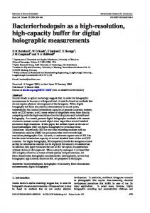
Fig. 1. Integer execution engine
the ROB size. The exception pointers use a 5-bit structure to index the branch ROB structure to update the branch predictor unit. All instructions are dispatched to different queues: integer, floating point, and load-store; a flag is activated (set) in the dispatched flag structure indexed by the tail pointer. At the same time, the tail pointer is stored in the in-flight tag field of IQ with the incoming instruction. When instructions are ready to be executed, they are issued to the functional units setting a flag in the issued flag structure pointed by the previously stored in-flight tag. A description of IQ’s operation can be found in [10, 11], in which the wakeup, allocation, and issue operations are presented in great detail. Each functional unit executes instructions and set a flag at execution ending in the executed flag structure entry indicated by the in-flight tag pointer. The number of 1-bit write ports in the executed flag structure is equal to the number of execution units of a processor. 3.1 Speculative Execution The branch predictor unit is responsible for speculative execution support. In each clock cycle, the fetch unit calculates the next program counter next-PC incrementing the PC-register. Meanwhile, the branch predictor unit uses the calculated next-PC value to look for branches and their respective destination addresses in the branch history buffer BHB in order to offer a
Computación y Sistemas Vol. 16 No. 1, 2012 pp 15-25 ISSN 1405-5546
Fig. 2. Fetch unit scheme
speculative program counter spec-PC for the next cycle. In the next clock cycle, instructions are fetched from a non-speculative or speculative path depending on the branch predictor decision (0-taken or 1-not taken) as it is shown in Figure 2. When branch instructions are decoded, the dispatch stage sets a flag in the branch flag structure indexed by the tail pointer. The superscalar processor schedules branch instructions in three sub-operations: 1) calculate the branch address destination, 2) resolve the branch condition, and finally, 3) verify the decision chosen by the branch predictor. 3.1.1 Branch Address Calculation The fetch unit uses one ACU to increment the program counter (see Figure 2) and the decode stage uses another one to compute the branch address destination (see Figure 3). Since branches are relative to a given PC, the address destination is computed using the PC and the branch instruction offset (PC+ sign extended offset). Performing the branch predictor updating at commitment requires both the PC and the offset values, and furthermore, the branch condition calculation. The previous two values demand an area along the reorder buffer, and this space is not exploited for all instructions in the window. Our design utilizes a small structure associated to the branch predictor unit for storing these values.
A Reorder Buffer Design for High Performance Processors 19
Fig. 3. Branch ROB scheme
The PC and the calculated destination address are stored in a structure smaller than the reorder buffer size, illustrated in Figure 3 as a Branch ROB. After the branch condition is calculated, the functional unit sets the branch decision flag (0taken or 1-not taken) and the executed flag (see Figure 1). Then, the branch and executed flags enable the exception pointer to select the corresponding Branch ROB entry. The PC and the branch target address are used to update the branch predictor. This action should be accomplished at the writeback stage to launch a recovery mechanism in the case of misprediction and reduce wrong path executions. 3.1.2 Resolving the Branch Condition The speculative behavior (taken/not-taken) of a conditional branch (beq rs, rt, offset) is resolved by comparing the processor registers (rs==rt). When the condition is computed as illustrated in Figure 1, the processor writes its result in the branch decision flag structure. Then, this result is used for the branch predictor unit to update its decision machinery and to signal all structures for recovering in case of misspeculation. In both cases, the exception pointer is used. 3.1.3 Verifying Branch Predictor Decisions Since instructions are unknown at the fetch cycle, a superscalar processor needs to resolve all
branch types in the same cycle via the branch predictor unit. Subsequently, more pipeline cycles are necessary to verify if the prediction was correct. Unconditional branches and return address are resolved by the branch predictor via a branch target buffer and a return address stack. However, conditional branches need to be predicted. The last step of turning a branch into a nonspeculative instruction is to verify the decision chosen by the branch predictor. This action starts when the conditional instruction has been executed by the functional unit setting the branch decision flags and the executed flag. The branch flag is set at dispatch once a given instruction has been decoded. These two conditions (the branch flag and the executed flag) are sufficient to select the E-pointer and the branch decision flag calculated by the processor as shown in Figure 3. The exception pointer is used to index the corresponding entry of the branch reorder buffer in order to read the information in the PC and the computed branch target address. The information obtained from the exception pointer and the branch decision flags are used by the branch predictor to verify past prediction. If the prediction was satisfactory, branch predictors set a non-speculative flag in the corresponding in-flight tag. For misspeculation, the fetch unit signals in all structures send the checkpoint for recovery. 3.1.4 Branch Predictor Unit Update When the predictor hits or misses in the prediction of conditional branches, the processor feedbacks to the branch predictor unit with the condition and the branch destination address calculated to improve confidence for future predictions. In the case of misses, together with the update action, the exception recovery mechanism is launched to clean the reorder buffer of incorrect path instructions. In the proposed model, branch decision flags and executed flags are set by the processor on the write-back stage. This condition is sufficient for selecting the corresponding entry of BROB to make the branch unit start updating as explained in Section 3.1.3, a fixed priority circuit can be used for the branch predictor unit update request logic.
Computación y Sistemas Vol. 16 No.1, 2012 pp 15-25 ISSN 1405-5546
20 José R. García Ordaz, Marco A. Ramírez Salinas, Luis A. Villa Vargas…
3.2 Physical Register Recycling Another support provided by the ROB is physical register recycling. The life time of a logical register is specified by the compiler, when the logical register is reused in the program, which means that the last value is no longer necessary in the execution code. Its associated physical register is considered old and must be recycled when the instruction is complete. Each renamed instruction has a current destination physical register and an old destination physical register; both registers are inserted in the ROB with the instruction at dispatch. The old destination ROB section works together with the renaming unit of free register list as shown in Figure 4. At commitment, old destination register tags are recycled to the free physical register pool and are used to turn off the register ready bits which are set by wakeup events while the current destination physical register tag is used to set the register valid bit in order to update the architectural state of the processor.
Fig. 4. Physical register recycling and update architectural state schemes
3.3 Load/Store Reorder Buffer LD/ST instructions are split into memory address calculation and the corresponding read or write action. A special address queue is used to store the immediate value, the base address register, the tag of the source or destination register, the in-flight tag, and the LS-Buffer entry assigned to memory instructions. A special LS-Buffer is used to store memory data, memory address, R/W bit, and in-flight tag as an interface to the memory port as shown in Figure 5. Memory address computations are resolved by the ACU and the results are written to the address field of the LS-Buffer. For loads, the destination register tags appoint the register file, to write the data read from memory. For stores, the source register is read from the register file and written to a LS-Buffer entry data field. Since memory access involves multi-cycle operations, the issue flag of the reorder buffer is set when the address calculation is sent to execution meanwhile the execute flag is set when the instruction memory access is complete.
Computación y Sistemas Vol. 16 No. 1, 2012 pp 15-25 ISSN 1405-5546
Fig. 5 LOAD/STORE instruction scheduling (LS-Queue and LS-Buffer)
3.4 Commitment Mechanism The superscalar processor makes a checkpoint of its state in each clock cycle through the rename units, issue queues, and register file by storing
A Reorder Buffer Design for High Performance Processors 21 Table 1. Processor configuration Element
P1
P2
ROB
128
B-ROB
08
32
32
F-I-C-Width
4-4-4/8-8-8
Brach Predictor
gshare, 2048-Entries
Branch Penalty
8-Cycles
Memory ports
2
L1 Data Cache L1 Inst. Cache L2 Unified Cache TLB
64
4-2-2/8-4-4 ALU-MUL-DIV
F.P. Functional Units
multiples copies in recovery structures. They map its status in shadow memories. Rename units use shadow maps, instruction queues use bit-vectors as valid entries, and the register file uses register ready bit and valid bit vectors. For example, in a 4-way processor, RATs of rename units maps four instructions in each cycle. This mapping corresponds to four instructions which will be allocated in one entry of the reorder buffer in the next cycle. Group commitment is the mechanism implemented in our design; it assists the processor’s state management and recovery while reducing design complexities with negligible impact performance. Figure 6 shows the structures of a reorder buffer organized in groups; here the instructions are fetched in a 4-way processor to illustrate group commitment scheduling. At dispatch, four instructions are inserted in the reorder buffer and each instruction sets a bit in its corresponding bit-vector dispatch structure. Instructions could be dispatched to any queue (IQ, FPQ, or LSQ), but when issued, each queue can set the corresponding issue flag in a 1bit vector issue structure. Executed flags are set by the functional units at the end of execution. A non-speculative flag is set by non-speculative instructions at dispatch and by the branch predictor unit when verifying the chosen decision for the branch predictor unit at write-back. When four consecutive instructions have been dispatched, issued, executed, and are not
16
L/S Queue Int. Functional Units
Fig. 6 Group commitment scheduling
P3
64K
1 Cycle
256K
10 Cycles
8-Entry, 4-Way, 8KB pages, 30 Cycles
Memory Latency
100
Cycles
speculative, the commitment mechanism augments the head pointer register for all structures of the reorder buffer, freeing resources such as the corresponding checkpoint copies and old destination registers. Note that the head pointer is a register of 7 bits split into a 5-bit part to index the ROB-entry and a 2-bit offset to select a precise in-flight instruction. This addressing mechanism allows fast and exact exception recovery. The 5-bit ROB entry matches the RAT copy index of the renaming unit and other checkpoint structures, while the 2-bit offset permits selecting the offending instruction exactly. 3.5 Exception Recovery When misspeculation is detected by the branch predictor unit, the checkpoint index is sent to all structures including the reorder buffer unit. This index is loaded to the tail pointer register invalidating all entries between the tail pointer and the head pointer, and their corresponding checkpoint copies. Finally, the status checkpoint copies of every processor structure, indexed by
Computación y Sistemas Vol. 16 No.1, 2012 pp 15-25 ISSN 1405-5546
22 José R. García Ordaz, Marco A. Ramírez Salinas, Luis A. Villa Vargas…
the tail pointer, are updated as the earlier processor status.
4 Evaluation The framework for evaluation is the Simplescalar Suite [1] with modifications presented in Section 3, compiled for the PISA architecture and configured with parameters as shown in Table 1. A subset of SPEC CPU2000 benchmarks were compiled for PISA and used as input. To explore the microarchitecture behavior, a dynamic subset of instructions of each benchmark consisting of 200M committed instructions were simulated, getting statistics after 100M forward instructions. a) SPECInt simulation results
Fig. 7. Average IPC performance for 4- and 8-way processors and different BROB size
4.1 Evaluating Commitment in Group First, we evaluated the impact of group commitment compared with individual commitment. For comparison purposes, 08-entry, 16-entry, 32-entry, and 64-entry BROB plus 128entry distributed ROB structures defined in Section 3 have been modeled and were compared with traditional 128-entry reorder buffer identified as 00-BROB. Figure 7 shows the average IPC performance, the results of simulating the subset SPEC CPU2000 integer and floating point benchmarks. The group commitment model allows the load-store
Computación y Sistemas Vol. 16 No. 1, 2012 pp 15-25 ISSN 1405-5546
b) SPECfp simulation results Fig. 8. 4-ways processor performance
instructions to be committed individually. The simulation results report a negligible negative impact on the processor performance. The worst cases are a 0.5% and 0.7% performance loss for 4-way and 8-way processors. 4.2 Measuring the Impact of the BROB Size Second, we evaluated the impact of the branch ROB structure size. Our model stops the fetch
A Reorder Buffer Design for High Performance Processors 23
a) SPECInt simulation results
Fig. 10. Percentage of branches executed ROB‐Occupancy
BROB‐Occupancy
90 80 70 60 50 40 30 20
The first consideration to select the optimal size of a Branch ROB is related with in-flight branch instruction average. Figure 10 shows the percentage of branches executed. Simulation reports (on average) 21.5 % of integer executed instructions and 12.5 % of floating point executed instructions corresponding to conditional branches.
Int.
64‐BROB
32‐BROB
16‐BROB
08‐BROB
00‐BROB
64‐BROB
32‐BROB
16‐BROB
activity when BROB becomes full until it has room to allocate new branches. Figures 8 and 9 show the processor performance for the four configurations of the branch-ROB structure a) for integer and b) for floating point for 4- and 8-way processors, respectively. We can observe a little performance loss for 08-BROB and 16-BROB, but for 32-BROB model there is no performance loss.
0 08‐BROB
Fig. 9. 8-way processor performance
10 00‐BROB
b) SPECfp simulation results
F.P.
Fig. 11 Average ROB and BROB instruction occupancy
4.3 Measuring the ROB/BROB Occupancy The second consideration for selecting the optimal size of a branch ROB is to conserve the reorder buffer instruction occupancy similar to the traditional reorder buffer identified as 00-BROB but modeled with a BROB size equal to the ROB size in order to compare both ROB and BROB
Computación y Sistemas Vol. 16 No.1, 2012 pp 15-25 ISSN 1405-5546
24 José R. García Ordaz, Marco A. Ramírez Salinas, Luis A. Villa Vargas…
occupancies. Figure 11 shows the average instruction occupancy. The baseline instruction occupancy is reached in the 32-BROB model. The BROB size is answered in part by the average of executed branches and it is fully answered with similar occupancy of the baseline reorder buffer.
5 Conclusions This paper presents a simple reorder buffer design based on distributed five 1-bit flag multiport structures (the dispatched flag, the branch flag, the issue flag, the execute flag, and the branch decision flag), two 7-bit multiport structures (the old destination register tag and the current destination register tag), and one 5-bit multiport structure (the exception pointer), which presents an easy solution for commitment and branch misprediction recovery. The new multiport structures have 1 write port, 1 read port for the dispatched flag and the non-speculative flag, 6 write ports, 1 read port for the issue flag and 14 write ports, 1 read port for the executed flag and the branch decision flag structures for a 4-way processor. The use of the group commitment scheme assists the recovery and the processor state management while reducing design complexities. The design proposes another hardware simplification by the use of a branch ROB, a small structure 25% of the ROB size to store the PC and the destination addresses of conditional branches. This microarchitecture allows updating the branch predictor unit as soon as the condition of the branch is resolved by the processor reducing unnecessary executions on the wrong path. The complete design does not cause a performance loss.
Acknowledgments This work has been partially supported by grants under agreements SIP-20101320 and SIP20101154 of the Graduate Studies and Research Department of the National Polytechnic Institute (IPN), Mexico, and by grants under agreements
Computación y Sistemas Vol. 16 No. 1, 2012 pp 15-25 ISSN 1405-5546
124104 and 115976 of the National Council for Science and Technology (CONACyT), Mexico.
References 1.
Burger, D. & Austing, T.M. (1997). The Simplescalar Tool Set Ver. 2.0. ACM SIGARCH Computer Architecture news, 25(3), 13–25. 2. Cristal, A., Ortega, D., Llosa, J., & Valero, M. (2004). Out-of-Order Commit Processors. 10th International Symposium on High Performance Computer Architecture (HPCA '04), 48–59. 3. Edmondson, J.H., Rubinfeld, P., Preston, R., & Rajagopalan, V. (1995). Superscalar Instruction Execution in the 21164 Alpha Microprocessor. IEEE micro,15(2), 33–43. 4. Hinton, G., Sager, D., Upton, M., Boggs, D., Carmean, D., Kyker, A., & Roussel, P. (2001). The Microarchitecture of the Pentium 4 Processor. Intel Technology Journal, 5(1), 1–13. 5. Kessler, R.E., McLellan, E.J., & Webb, D.A. (1999). The Alpha 21264 Microprocessor Architecture. IEEE micro, 19(2), 24–36. 6. Kucuk, G., Ponomarev, D.V., Ergin, O., & Ghose, K. (2004). Complexity-Effective Reorder Buffer Designs for Superscalar Processors. IEEE Transaction on Computers, 53(6), 653–665. 7. Leibholz, D. & Razdan, R. (1997). The Alpha 21264: A 500mhz out-Of.Order Execution Microprocessor. IEEE COMPCON 97, San Jose, CA , USA, 28–36. 8. Lenell, J., Wallace, S., & Bagherzadeh, N. (1992). A 20mhz Cmos Reorder Buffer for a Superscalar Microprocessor. 4th NASA Symposium on VLSI DESIGN, Idaho, Moscow, 2.3.1–2.3.12. 9. Martí, S.P., Borrás, J.S., Rodríguez, P.L., Tena, R.U., & Marín, J.D. (2009). A Complexity-Effective out-of-Order Retirement Microarchitecture. IEEE Transactions on Computers, 58(12), 1626–1639. 10. Ramirez, M.A., Cristal, A., Veidenbaum, A.V., Villa, L., & Valero, M. (2005). A New Pointer-Based Instruction Queue Design and Its PowerPerformance Evaluation. 2005 IEEE International Conference on Computer Design: VLSI in Computers an Processors, San Jose CA, USA, 647–653. 11. Veidenbaum, A.V., Ramirez, M.A., Cristal, A., & Valero, M. (2008). Pointer-Based Instruction Queue Design for out of Order Processors. US 2008/0082788A1
A Reorder Buffer Design for High Performance Processors 25 12. Wang, C.J. & Emnett, F. (1993). Implementing Precise Interruptions in Pipeline Risc Processors. IEEE micro, 13(4), 36–43. 13. Yeaguer, K. C. (1996). The Mips R10000 Superescalar Microprocessors. IEEE micro, 16(2), 28–41.
José R. Garcia received his B.Sc. degree in Electronic Engineering from the Autonomous University of Puebla, Mexico, in 2005. He is a M.Sc. student of the Computer Engineering Program at the Microtechnology and Embedded System Laboratory of the Center for Computing Research of the National Polytechnic Institute (CIC-IPN), Mexico. He is also an intern with GDC Intel Labs, Mexico. His research interests include high-performance computer microarchitecture and digital systems design based on HDL, FPGA and VLSI systems. Cuauhtémoc Peredo received his B.Sc. degree in Electrical Engineering and his M.Sc. degree in Computer Engineering from the National Polytechnic Institute (IPN), Mexico. He is a member of the Center for Computing Research of IPN and a Ph.D. student of ESAII of the Polytechnic University of Catalonia, Spain. His research interests are digital systems, fuzzy logic, and digital control. Marco A. Ramirez received his B.Sc. degree in Electronic Engineering (1995) and a M.Sc. degree in Computer Engineering (2002) from the National Polytechnic Institute (IPN), Mexico. In 2007, he received his Ph.D. degree in Computer Science from the Polytechnic University of Catalonia, Spain. Since January 1997, he has been with the Center for Computing Research of the National Polytechnic Institute (CIC-IPN),
Mexico. His research interests include highperformance computer microarchitecture, digital system design based on HDL and FPGA for modeling microprocessors, and VLSI design for energy-efficient computing. Luis A. Villa received his B.Sc. degree in Electronic Engineering (1992) and his M.Sc. degree in Computer Engineering (1994) from the National Polytechnic Institute (IPN), Mexico. In 1999, he received a Ph.D. degree in Computer Science from the Polytechnic University of Catalonia, Spain. From December 1999 to February 2001, he was with the Laboratory for Computer Science as a Postdoctoral Fellow at the Massachusetts Institute of Technology, working in the SCALE project. From October 2001 to January 2007, he was with the Mexican Petroleum Institute. Since January 2007, he has been with the Center for Computing Research at the National Polytechnic Institute (CIC-IPN), Mexico. His research interests include high-performance computer microarchitecture and VLSI design for energyefficient computing. Herón Molina received his B.Sc. degree in Electronic Engineering from the National Polytechnic Institute (IPN), Mexico, in 1991 and in 1995, his Ph.D. degree in Electrical Engineering from the Research Center for Advanced Studies (CINVESTAV), Mexico. From October 1998 to April 2008, he was with the Interdisciplinary School of Engineering and Advanced Technologies (UPIITA). Since May 2008, he has been with the Center for Computing Research of the National Polytechnic Institute (CIC-IPN), Mexico. His research interests include CMOS analog and digital VLSI circuit design, neuro-fuzzy systems and bioinformatics.
Article received on 01/02/2010; accepted on 15/04/2011.
Computación y Sistemas Vol. 16 No.1, 2012 pp 15-25 ISSN 1405-5546