A Reuse-Oriented Development Process for Component-based Robotic Systems D. Brugali1
L. Gherardi1
A. Luzzana1
A. Zakharov2
1 University of Bergamo, DIIMM, Italy {brugali,luca.gherardi,andrea.luzzana}@unibg.it 2 GPS GmbH, Stuttgart, Germany
[email protected]
Abstract. State of the art in robot software development mostly relies on class library reuse and only to a limited extent to component-based design. In the BRICS project we have defined a software development process that is based on the two most recent and promising approaches to software reuse, i.e. Software Product Line (SPL) and Model-Driven Engineering (MDE). The aim of this paper is to illustrate the whole software development process that we have defined for developing flexible and reusable component-based robotics libraries, to exemplify it with the case study of robust navigation functionality, and to present the software tools that we have developed for supporting the proposed process.
1
Introduction
The routine use of existing solutions in the development of new systems is a key attribute of every mature engineering discipline. Software reuse is a state of the practice development approach in various application domains, such as telecommunications, factory automation, automotive, and avionics. Software Engineering has produced several techniques and approaches for promoting the reuse of software in the development of complex software systems. A survey can be found in [3] (Sidebar A Historical Overview of Software Reuse). In Robotics, software reuse is typically conceived as cut and paste of code lines from program to program: this practice is called opportunistic software reuse and might work only for the development of simple systems (e.g. for educational purposes) or for unique systems (e.g. a research prototype). In contrast, the development of industrial-strength robotic systems that aim to become commodity, require a systematic approach to software reuse. Systematic software reuse is the routine use of existing software or software knowledge to construct new software, so that similarities in requirements, architectures and design between applications can be exploited to achieve substantial benefits in productivity, quality and business performance. If a company that commercializes integrated robotic systems wants to achieve customer value through large commercial diversity with a minimum of technical diversity at minimal cost, the best approach to software development is the Software Product Line (SPL)[5].
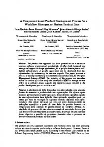
An SPL is a set of applications (products) that share many (structural, behavioral, etc.) commonalities and together address a particular domain. The term domain is used to denote or group a set of systems (e.g. mobile robots, humanoid robots) or functional areas (motion planning, deliberative control), within systems, that exhibit similar functionality. Each new application is built from the SPL repository of common software assets (e.g. architectural and design models, software components). In the BRICS project we have defined a software development process that exploits the SPL approach and accounts for two peculiarities of the robotics field: – Today, a huge corpus of software applications, which implement the entire spectrum of robot functionality, algorithms, and control paradigms, is available in robotic research laboratories and potentially could be reused in many different applications. Typically, their interoperability or their extensions towards novel applications require high efforts. Any company that aims at developing professional software for complex robotic systems has to make an initial investment in refactoring and harmonizing existing open source robotics libraries that implement the robot functionalities offered by the SPL. This phase is typically called software development for reuse. – Typically, robotic systems integrators are not software engineers and do not master advanced software development techniques adequately. For this reason, the proposed development process exploits the Model-Driven Engineering (MDE) [15] approach. According to the MDE approach, robotic system integrators use domain-specific languages to build models that capture the structure, behavior, and relevant properties of their software systems. A new application is developed by reusing these models, customizing them according to specific application requirements, and semiautomatically transform models and even generate source code using transformation engines and generators. This phase is typically called software development with reuse. Figure 1 illustrates the phases of the reuse-oriented development process described in this paper. The first two phases, namely software refactoring and product line design, are intended to produce software for reuse. The remaining two phases, namely Variability modeling and Variability resolution, support the development of software with reuse. In the upper part of Figure 1, the conceptual and software tools that support the process are linked to the various phases, namely Refactoring Patterns [6], the BRICS Component Model (BCM )[9], the BRICS Integrated Development Environment (BRIDE)[9], and the BRICS tool for variability modeling and resolution (FODA). In the lower part of the figure the input open source libraries and the intermediate products of the development process are represented, namely the BRICS class libraries, the Product Line models, the Variability models (features models), and the Application models. This paper aims to illustrate the whole software development process that we have defined for developing flexible and reusable component-based robotics libraries, to exemplify it with the case study of the robust navigation, and to present the software tools that we have developed for supporting the robotic engineers in modeling and resolving variability in component-based robotics systems.
Refactoring Patterns
BRICS Component model
Code Refactoring
Open Document Document Source Libraries
BRIDE Tool
Product Line Design
BRICS Document Document Class Libraries
Document Product Document Line Model
FODA Tool
Variability Modeling
Variability Resolution
Document Feature Document Model
Document Application Document Model
Fig. 1. The development process
The paper is structured as follows. Section 2 illustrates state of the art open source libraries that provide robust navigation functionality. Sections 3 to 6 present the four phases of the development process and exemplify them with the robust navigation case study. Finally Section 7 draws the relevant conclusions.
2
The Robust Navigation Case Study
Robust navigation is the ability of a mobile robot to perform autonomous navigating, while avoiding dangerous situations such as collisions with obstacles. It is a cross-sectional domain, which includes path planning, motion control and sensor data processing. From an algorithmic point of view, the challenging task is to organize an efficient interaction between these functionalities in order to maximize performance, safety, and robustness. Mobile robot navigation algorithms have been a research topic for several decades (see [16] for a taxonomy). Existing algorithms could be roughly classified as one- and multi-step methods. One-step methods directly convert the sensor data to a motion commands. Majority of one-step algorithms are either based on classical planning or on the potential fields approaches [16]. Today, they are rarely used due to their inability to cope with dynamic environment and vehicle constraints. Multi-step methods (e.g. Dynamic Window Approach [8], Vector Field Histogram [17], Nearness Diagram [12]) overcome these limitations by creating a local map of the environment around the robot and performing local planning by computing possible motion directions (Nearness Diagram) and velocities (VHF) taking into account distance to the goal or to a precomputed path. From a software development point of view, the challenge is to implement robust navigation functionality as a set of reusable components that can be assembled into flexible systems3 . For this purpose, the BRICS project applies a novel approach to software development, which avoids to develop from scratch robot functionalities based on yet another software architecture. Instead, by collecting and analyzing well known open source libraries providing robotics 3
The IEEE Standard Glossary of Software Engineering Terminology defines flexibility as the ease with which a system or component can be modified for use in applications or environments other than those for which it was specifically designed.
functionalities, we aim at identifying those architectural aspects (i.e. entities, data structures, interfaces, relationships) that are common to all or most of the implementations of the same family of functionalities, and those aspects that distinguish one implementation from another. These common architectural aspects represent the stable characteristics of a family of functionalities and are likely to remain stable through future implementations of the functionalities. By analyzing existing robust navigation libraries (see table 1) we have realized that typically they refer to the same functionality using different names. In some cases, the functionality is not even mentioned but is implicit in the implementation. – Motion planning (aka BaseGlobalPlanner, PathPlanner): is the process of computing a collision-free global path in a static environment between a given start position and a given goal position. The path is typically represented as a sequence of intermediate waypoints. – Trajectory generation (aka ParameterizedTrajectoryGenerator, DWAPlanner): is the process of refining a path for introducing velocity information. A trajectory defines the planned positions of the robot over the time and is typically represented as a sequence of positions with an associated velocity. – Obstacle detection and representation (aka CostMap2D, OgMap): is the process of using sensors information (e.g. laser scans) in order to detect the positions of the obstacles around the robot. This information is then used for creating and updating a map of the environment. – Obstacle avoidance (aka Local LocalBaseNavigation, LocalNav, CAbstractHolonomicReactiveMethod): is the process of adapting the precomputed trajectory while the robot is moving in order to avoid unexpected obstacles that occlude the path. – Position and velocity control (aka LocalBaseNavigation, LocalNav, MotionController): is the process of generating velocity commands to the robot in order to move it along the computed trajectory. This functionality has a strong dependency with the kinematics model, which is often implicit in the library implementations. – Localization (aka FaithLocaliser, amcl): is the process of estimating the robot position with respect to a global reference frame. In the simplest case this functionality is implemented by using only the robot odometry but other sensors can be used to improve the odometric estimation.
3
Software Refactoring
Software refactoring is the process of changing a software system in such a way that it does not alter the external behaviour of the code yet improves its internal structure [7]. It occurs at two complementary levels: (a) Syntactical refactoring is a behavior preserving transformation that, through the adoption of good design principles (abstraction, information hiding, polymorphism, etc.) aims at making software artifacts modular, reusable, open. (b) Semantic refactoring is a
Type
Method
Library Name
Global Planners
Carrot planner, Dijkstra’s alg. ARA*, Anytime D*, ANA* Sampling-based Planning
ROS SBPL/ROS OOMPL, BRICS MM
Trajectory Generation
reactivenav::CPTG1 - CPTG7
MRPT
Local planners
VFF VFH+ Dynamic Window Trajectory Rollout Nearness Diagram Elastic Band
MRPT Player/Stage, ORCA ROS, Sunflower ROS MRPT ROS
Mapping
gmapping, costmap 2d ogNode, ogMap
ROS ORCA
Localization
amcl ICP SLAM, RBPF SLAM, ...
ROS MRPT
Table 1. Open source libraries for robust navigation
domain-driven transformation that, through a careful analysis of the application domain (commonality/variability and stability analysis), enhances software artifacts flexibility, adaptability, and portability. Software refactoring brings many advantages not immediately but in a long time. The initial cost in terms of time and effort spent for rewriting the code is balanced by the time gained in future. This gain is due to a code more readable, more reusable and more maintainable. The result of a refactoring process is a library of classes that are middleware-independent, are organized in a hierarchy of abstraction levels, provide harmonized interfaces (API), and implement a variety of algorithms. In a previous paper [2] we have described how architecture refactoring patterns have been applied to refactor motion planning software libraries. Refactoring patterns provide guidelines to redistribute the responsibilities among the classes of a software library, to harmonize the common data structures and to reduce the coupling degree. 3.1
Case study: the ROS Navigation Stack
This section presents the architecture of an open-source library, which provides a mobile-based navigation functionality. We selected ROS framework because of its popularity in robotic community. Figure 2 shows a portion of the class diagram that represents the architecture of the ROS navigation stack. Class BaseGlobalPlanner is an interface of the global planners used in navigation stack. There are two implementations: CarrotPlanner and NavfnROS. First one is a simplistic planner, which connects a target pose and robot actual pose with a straight line and performs collision checks along this line. The second is a grid-based A* path-planner for circular robots. Multiple functionalities are tightly coupled in the implementation of class BaseLocalPlanner, i.e. trajectory generation, adaptation and execution. It generates a number of trajectories for admissible linear and angular velocities of the robot. Each trajectory is scored according to an objective function, which
Odometry
Pose
TransformListener
PointCloud/LaserScan
MoveBase
BaseLocalPlanner
TrajectoryPlannerROS
Twist
DWAPlannerROS
Map
Costmap2D
BaseGlobalPlanner
CarrotPlanner
NavfnROS
Fig. 2. Mobile base navigation component in ROS
includes goal heading, path heading and obstacle clearance. The trajectory with maximum objective function is selected and its associated linear and angular velocity (twist) are sent to the robot driver. Two concrete implementations of this class are available, namely TrajectoryPlannerROS and DWAPlannerROS. Both assume implicitly that the robot has a differential drive kinematics model. Class CostMap2D is an implementation of 2D occupancy grid-map. It embeds the data structures for representing a 2D tessellated representation of the environment. It is used for both path planning and obstacle avoidance. The top-level class is the MoveBase class, which instantiates all the classes that implement specific functionality and starts several threads for their concurrent execution. Concurrent access to shared resources (e.g. the map of the environment) is synchronized by means of infrastructure mechanisms, such as a state machine, mutexes and numerous flags and conditions across the code. There is thus no guarantee that these functionalities are executed in real-time. The MoveBase class is instantiated by a main function that starts a ROS node. Thus, all the functionalities for robust navigation are provided by a single component (ROS node). This component interacts with other components in the system (e.g. the robot base driver and the laser driver) by exchanging ROS messages. The set of exchanged messages represent the component interface. Unfortunately, the component interface is not clearly separated by the component implementation since ROS messages are produced and consumed by several classes that implement the component. Thus, the only way to understand how components interact with each others is to carefully look at the source code. The ROS Navigation stack classes implementations are tightly coupled with the ROS infrastructure, thus they cannot be reused in different environments.
4
Product Line Design
In [4] we have defined a set of architectural principles for the development of flexible component-based systems that foster the separation of four design concerns originally identified in [13], namely Computation, Coordination, Communication, and Configuration. According to these architectural principles, the robot functionalities are provided by Computation components that have harmonized interfaces and implement specific robotic algorithms. The clear separation between component inter-
face and implementation guarantees interoperability of components that provide similar functionalities but implement different algorithms. The mutual interactions of Computation components might change dynamically according to their current internal state. In order to improve their reusability, interaction policy should be implemented as finite state machines in specialized Coordination components that observe state transitions in the systems by listening to events notified by Computation components. Typically, components rely on a middleware infrastructure to exchange data and events through the network. In order to make components implementations independent from any specific middleware, components should be designed and implemented according to an abstract component model (meta-model), which defines middleware-independent communication ports. For this purpose, similarly to the OMG initiative4 , the BRICS project has defined a new component model (BCM [9]), which provides the following architectural elements: – Component: is a software package that encapsulates a set of related functionalities and has its own thread of control. – Port: represents the component interface. It explicitly defines (in terms of data types and contract) how a component provides (output port) or requires (input port) a service or a data-flow. – Property: allows the component configuration. A property provides an interface for setting the value of a parameter defined in the component implementation (e.g. period, algorithm parameters, . . . ). – Connector: defines the connection between an input port and an output port and its communication mechanism. Computation components and Coordination components can be assembled to build applications. A family of similar applications that are built reusing a set of software components and share the same architecture is called a Software Product Line. The product line architecture specifies the structural (data structures and application programming interfaces) and behavioral (data and control flow) commonalities among the products and the variations reflected in each product (variation points). It prescribes how software components (variants) can be assembled to derive individual products. For example, a variation point in the robust navigation product line is the algorithm for obstacle avoidance. Different algorithms (i.e. dynamic window approach [8] or vector field histogram [17]) are implemented as distinct software components. The product line architecture guarantees that these components are interchangeable. The possible configurations of a software product line are represented in a product line model, which specifies (a) a set of components that can be used for building all the possible applications of the family (some of them are mandatory, some others are instead optional) and (b) a set of connections among components (some of them are stable, some others are variable). By selecting the optional components, their specific implementation, the values of their configuration parameters, and the variable connections, the variability of the product line is resolved and a specific application model is defined. 4
http://www.omg.org/spec/RTC/1.0/
Trajectory Planner
Goal
Coordinator Event
Trajectory Event Trajectory Adapter laserScannerId robotModel
Event
Event
Pose Tracker
Trajectory Follower robotModel
Marker Pose
Marker Id
Trajectory
Marker Locator Pose RW
Robot Pose & Twist
cameraId Image
Laser Scan Twist Laser Scanner Driver
Robot Driver
laserScannerId
robotModel
RGB Camera Driver Odometry
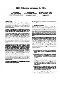
Fig. 3. The model representing the BRICS Robust Navigation Product Line
4.1
The BRICS Robust Navigation SPL
Figure 3 represents a first draft of the BRICS Robust Navigation Product Line. Continuous lines depict the default connections between input and output ports while dashed lines represent the optional connections that may be created to configure a specific application. Continuous boxes represent mandatory components, while dashed boxes represent optional components. Boxes inside components indicate their properties. More specifically: – Trajectory Planner implements the motion planning and trajectory generation functionalities. It gets a goal position and the current robot position as input and produces a trajectory that is a vector of poses with twist. – Trajectory Adapter interpolates the precomputed trajectory and produces an obstacle-free trajectory toward the next waypoint taking into account the sensor information produced by the laser scanner. – Trajectory Follower receives the adapted trajectory and the robot estimated pose and produces as output a twist for following the input trajectory. – Robot Driver drives the physical robot. It receives twist commands and produces the robot odometry. – Laser Scanner Driver reads the raw data from the device and produces as output the laser scans expressed as a vector of distances and angles. – Pose Tracker keeps track of the current pose and twist of the robot. It fuses odometry estimates with position estimates computed by other components. – Marker Locator is an optional component, which is in charge of localizing visual markers placed in the environment and computing their positions with respect to a global reference frame. It receives as input an image and the odometry of the robot and produces as output the absolute marker position. – RGB Camera Driver is an optional component, which reads data from the RGB camera and produces as output an RGB image. – Coordinator implements the coordination logic among components. It monitors events generated by components that could represent abnormal situations (e.g. the Trajectory Adapter cannot generate a trajectory to avoid an
obstacle) and generates events that triggers state changes in other components (e.g. the Trajectory Planner should plan a new trajectory). There are some important differences between the proposed solution and the ROS navigation stack discussed in Section 3. First of all the navigation functionalities are mapped to finer grained components. Each component has only one thread of control. This allows to replace individual functionalities easier and to select the most appropriate frequency for each functionality. Accordingly, the trajectory follower and the trajectory adapter functionalities are implemented in two different components. This separation reflects the different operating frequencies of the two components: the Trajectory Follower runs at a higher frequency, as required by the closed loop position and velocity control algorithm. On the contrary the Trajectory Adapter component computes a new output only when receives a new laser scan or a new trajectory. Unlike in ROS, the coordination mechanisms have been made independent from the components implementations by introducing a Coordinator component.
5
Variability Modeling
Building software systems according to the product line approach is economic and efficient [5]. Most work is about integration, customization, and configuration instead of creation. A system configuration is an arrangement of components and associated options and settings that completely implements a software product. Variants may exclude each others (e.g., the selection of a component implementing an indoor navigation algorithm excludes the choice of components providing GPS-based localization services) or one option may make the integration of a second one a necessity (e.g., a component implementing a visual odometry algorithm depends on a component that supplies images of the environment). Hence, only a subset of all combinations is the admissible configuration. In order to model and symbolically represent the product line variation points, their variants and the constraints between them, a formalism called Feature Models was introduced in 1990 in the context of the Feature Oriented Domain Analysis (FODA) approach [11]. These models make explicit the variability that is implicitly defined during the product line design. A feature model is a hierarchical composition of features. A feature defines a software property and represents an increment in program functionality. Composing features, i.e. selecting a subset of all the features contained in a feature model, corresponds to select a specific product (application) that belongs to the product line described by the model. This selection is usually called instance. Feature models are organized as a tree and the root feature, also called concept, defines the application family. Parent features are connected to children features by means of edges, which represent containment relationships. Features can be discerned in two main categories: mandatory and optional. Mandatory features have to be present in all the application of the product line (commonalities). They are graphically depicted by means of a black circle on the top.
Optional features instead can be present but they are not mandatory (variation points). They are depicted by means of a white circle on the top. Three types of containment relationships define containment constraints between the parent and the children features: one-to-one, or and alternative. The one-to-one containment means that the parent feature can (or has to) contain the child feature. The other two kinds of containments are containments between the parent feature and its children features. Here the parent feature is the variation point, while the subfeatures the variants. The or containment means that from the children features at least one has to be present in the application. The alternative containment (X-Or) instead means that from the children features only one can be present in the application. Feature models also define two kinds of constraints between the features: requires and excludes. These constraints allow the definition of a subset of valid configurations. The requires constraint means that if a feature A is selected, then also a feature B has to be selected. The excludes constraint instead means that if a feature A is selected, then a feature B cannot be selected. [10] presents an Eclipse plugin that allows the design of feature models. This plugin provides a formal meta-model (Ecore based), which defines the rules for creating feature models conform to the standard specification introduced above. 5.1
Variability in the BRICS Robust Navigation SPL
Figure 4 depicts the feature model describing the variability of the BRICS Robust Navigation Product Line. Gray boxes represent the or and alternative containments relationship and show the cardinality (1. . . n represents or and 1. . . 1 represents alternative). It contains four main variation points: – Localization: this variation point regards the information used for localizing the robot. Using the odometry is mandatory but a marker locator can be used in order to improve the pose estimation. – Navigation: this variation point regards the navigation strategy. Two variants are available: map-based and marker-based. In the first case a Trajectory Planner computes a collision-free path according to the goal received as input from its client. In the second case instead the goal is provided by the Marker Locator and represents the position of a specific marker. – Obstacle Avoidance: this variation point regards the algorithm used for avoiding obstacles. Two variants are available: Dynamic Windows Approach and Vector Field Histogram. – Sensors: this variation point regards the sensors used in the application. Using the laser scanner is mandatory for obstacle avoidance. However, in order to recognize visual markers, the robot equipment can be extended by using a front camera and a camera held on a specific support. The feature model also defines the following three constraints that limit the allowable combinations of features. (a) The use of the marker-based navigation strategies requires at least one of the two cameras. (b) The same requirements
Fig. 4. The model representing the variability in the BRICS RN Product Line. It was designed with our Feature Model plugin
are valid when we want to use the markers for localization. (c) The selection of a marked based navigation excludes the use of the markers for the localization.
6
Variability Resolution
The last phase of development process regards the resolution of the variability in the Product Line model and has the goal of producing the model of a specific application. Thanks to our tool this can be done by selecting the set of variants (features), which reflect the application requirements, directly on the feature model. This selection should satisfy the explicit constraints, the containments cardinalities and the selection of the mandatory features defined in the feature model. The tool automatically checks the constraints satisfaction and only successively generates the application model, which can be transformed in the deployment file of a specific middleware by means of the model-to-text transformation provided by BRIDE. In order to define how the Product Line model has to be modified for producing the model of a specific application, we introduced the concept of transformation. A transformation is an action that modifies the architectural elements of a Product Line model in order to replace a variation point with a specific variant. Different kinds of transformations are available, according to the elements that have to be modified (components implementations, connections, properties). The developer can associate to each feature one or more transformations. A selection of a set of features will hence result in the execution of a set of transformations. Figure 5 illustrates how the meta-model of the feature models described in [10] has been extended for representing the transformation associated to the features. Currently it has been done only for the generation of Orocos RTT application. For this reason the meta-model has three links to three elements defined in the RTT-BCM meta-model: Task Context, Connection Policy, and Property [1]. However the approach can be easily extended to other middlewares such ROS and SCA [14]. The following list describes the different kinds of transformations. – TransfImplementation: defines which implementation will be used for a certain component, i.e. which algorithm (Computation and Coordination). The developer specifies a link to the desired component (defined in the Prod-
Fig. 5. The extension of the feature model meta-model that specifies how transformations are mapped to RTT elements (classes with the arrow on the top right corner)
uct Line model) and the class that implements its interface (by means of the namespace and the class name). – TransfConnection: defines how the components will be connected (Composition). The developer specifies a link to a connection that has to be removed from the Product Line model (if needed) and a set of connections that have to be created (with specific lock policies and the buffer sizes). As a result of these transformations unconnected components will be removed from the model. – TransfProperty : defines the value of a certain property (Configuration). The developer specifies a link to the desired property (defined in the Product Line model) and the value he wants to assign to it. 6.1
Variability resolution in the BRICS Robust Navigation SPL
The product line presented in the previous sections allows the deployment of different applications that can be classified according to two navigation strategies: map-based and marker-based. The different strategies can be derived by resolving the Navigation variation point. If a map-based navigation is chosen, then the Marker Locator, the RGB Camera Driver components and all the connections between these components and the others are not necessary. So these components can be removed from the model. In case of marker-based navigation instead, the Trajectory Planner component receives the goal from the Marker Locator. Hence the optional connections of Marker Locator and RGB Camera Driver have to be created. In addition to these connections, the Coordinator implementation and its connections have to be defined according to the navigation strategy. The Coordinator always recovers from situation in which the Trajectory Adapter is unable to adapt the trajectory. This can happen due to the presence of obstacles all around the front part of the robot. In these cases, the Coordinator receives
an event from the Trajectory Adapter and returns an event to the Trajectory Planner asking it to recompute a path. When a marker-based strategy is chosen instead, the Coordinator resolves also situations in which no markers can be detected. In these cases the Coordinator receives an event from the Marker Locator an returns an event to the Trajectory Planner asking it to create a trajectory for moving the robot in such a way to seek new markers. This configuration needs a connection between the Event interfaces of Marker Locator and Coordinator. From this point several applications belonging to the two groups can be derived by resolving the other variation points. The Localization based on marker can be deployed by connecting the Pose RW interface of the Marker Locator to the Pose Tracker. The obstacle avoidance variation point can be resolved by setting the implementation of the Trajectory Adapter in order to use one of the two algorithms (DWA or VHF). Finally the Sensors variation point can be resolved by setting the implementation of the sensors drivers and configuring the property of the MarkerLocator in order to specify the camera Id. This value is needed in order to retrieve the camera position from the robot kinematic model. The feature model depicted in figure 4 defines for each feature the transformations that allow the resolution of the variation points. Some examples of the transformations associated to the features are reported below. – Feature Marker-based. (a) Connection transformation. New connections between: Goal interface of Trajectory Planner and Marker Pose interface of Marker Locator, Event interfaces of Coordinator and Marker Locator, Event interfaces of Trajectory Adapter and Coordinator. (b) Implementation transformation: set the implementation of the coordinator for resolving situations in which no markers are visible. – Feature DWA. In this case a single Implementation transformation is defined, which sets the implementation of the Trajectory Generator for using the Dynamic Window Approach. – Feature Front Camera. (a) Property transformation: set the value of the cameraId property of the marker locator to the Id of the front camera. (b) Implementation transformation: set the implementation of the RGB Camera Driver for using the driver of the appropriated camera.
7
Conclusions
In this paper we have presented the BRICS software development process for robotic component-based systems that builds on the concept of software flexibility. The key to achieving software flexibility is the possibility to identify the class of changes that are likely to occur in the environment over the lifespan of robotic software components and that affect components and systems portability, interoperability, and reusability. The BRICS approach to robotic software development consists in refactoring existing open source robotic libraries according to flexible architectures, which clearly separate stable and variables characteristics.
By explicitly modeling software variability, it is possible to build new applications by selecting and integrating components that provide concrete implementations (variants) of robotic functionalities (variation points).
8
ACKNOWLEDGMENTS
The research leading to these results has received funding from the European Community’s Seventh Framework Programme (FP7/2007-2013) under grant agreement no. FP7-ICT-231940-BRICS (Best Practice in Robotics). The authors would like to thank all the partners of the project for their valuable comments.
References 1. The RTT meta model. http://www.best-of-robotics.org/bride/rtt.html. 2. D. Brugali, W. Nowak, L. Gherardi, A. Zakharov, and E. Prassler. Componentbased refactoring of motion planning libraries. In IEEE/RSJ Int. Conference on Intelligent Robots and Systems (IROS), pages 4042–4049, 2010. 3. D. Brugali and P. Scandurra. Component-based robotic engineering (part i)[tutorial]. Robotics & Automation Magazine, IEEE, 16(4):84–96, 2009. 4. D. Brugali and A. Shakhimardanov. Component-based robotic engineering (part ii)[tutorial]. Robotics & Automation Magazine, IEEE, 17(1):100–112, 2010. 5. P. Clements and L. Northrop. Software Product Lines: Practices and Patterns. Addison-Wesley, 2002. 6. S. Demeyer, S. Ducasse, and O. Nierstrasz. Object-oriented reengineering patterns. Morgan Kaufmann, 2008. 7. M. Fowler and K. Beck. Refactoring: improving the design of existing code. Addison-Wesley Professional, 1999. 8. D. Fox, W. Burgard, and S. Thrun. The dynamic window approach to collision avoidance. Robotics & Automation Magazine, IEEE, 4(1):23–33, 1997. 9. H. Garcia and H. Bruyninckx. Tool chain (bride) delivered as brics software distribution. BRICS Deliverable 4.4, 2011. 10. L. Gherardi and D. Brugali. An eclipse-based feature models toolchain. In 6th Italian Workshop on Eclipse Technologies (EclipseIT 2011), 2011. 11. K. Kang. Feature-oriented domain analysis (FODA) feasibility study. Technical report, DTIC Document, 1990. 12. J. Minguez and L. Montano. Nearness diagram (nd) navigation: collision avoidance in troublesome scenarios. IEEE Transactions on Robotics and Automation, 2004. 13. M. Radestock and S. Eisenbach. Coordination in evolving systems. In Proceedings of the Int, Workshop on Trends in Distributed Systems CORBA and Beyond, pages 162–176. Springer LNCS vol. 1161, 1996. 14. Service Component Architecture (SCA). http://www.osoa.org. 15. D. Schmidt. Guest editor’s introduction: Model-driven engineering. Computer, 39(2):25–31, 2006. 16. B. Siciliano and O. Khatib. Springer handbook of robotics. Springer-Verlag New York Inc, 2008. 17. I. Ulrich and J. Borenstein. Vfh+: Reliable obstacle avoidance for fast mobile robots. In IEEE Int. Conference on Robotics and Automation, 1998.