A Robust Speed-Based Handover Algorithm for Dense Femtocell/Macrocell LTE-A Network and Beyond Olusegun O. Omitola and Viranjay M. Srivastava Department of Electronic Engineering, University of KwaZulu-Natal, Durban – 4041, South Africa
[email protected]
Abstract—Femtocells are currently being deployed in the present generation of cellular networks because of their ability to provide increased data rate at home and offices. This development together with the recent advances in technology brings about a huge increment in bandwidth required to meet the future demand for data by the ever increasing mobile devices. It is envisaged that with dense deployment of femtocells, the present challenge in terms of data requirement as well as the future demand will be met. Therefore, it is imperative to intensify the research in the area of handover management in femtocell/macrocell integrated network using a high dense network scenario that will dominate the future network. Presently, most research works in this area do not focus much on a dense deployment of mobile users in a femtocell/macrocell integrated network. Also, many existing handover algorithms were not designed to work in a highly mobile and dense environment. In this work, the authors propose a robust CAC handover algorithm for a dense femtocell/macrocell LTEAdvanced integrated network. The proposed CAC algorithm is efficient to handle calls in a highly dense and mobile user environment. The simulation results of the proposed algorithm show that the handover call dropping probability, call blocking probability and handover probability are considerably reduced. Index Terms—Call Admission Control (CAC); Dense Network; Handovers; Femtocell; Macrocell; LTE-A.
I. INTRODUCTION Mobile cellular networks are becoming more complex due to the emergence of several technologies and the needs to increase the bandwidth to meet the present and future data demands by the always increasing billions mobile devices around the world. With more than 50 billion human and machine-to-machine devices envisaged in the future [1], the present cellular system will be challenged. In addition, to support variety of services, different data rates and many user types in the future, there is an urgent need to improve the performance of the present cellular 4G systems through the use of wider bandwidth. LTE-A also known as true 4G stands for Long Term Evolution-Advanced. This work started as a project by 3GPP (Third Generation Partnership Project) in 2004 as LTE and published in 2009 as Release 8 specifications [2]. System performance was improved in LTE using wider bandwidths
whenever the spectrum is available; however, there was no improvement in spectral efficiency. To improve the LTE performance in the framework of LTE Advanced, 3GPP worked on the various areas including Orthogonal Frequency Division Multiple Access (OFDMA), carrier aggregation (multiple component carriers), massive Multiple Inputs Multiple Outputs (massive MIMO) and heterogeneous networks (femtocells, microcells, and picocells) [1, 4]. LTE-A is backward compatible with LTE and can be deployed in the same spectrum used by the LTE without affecting the LTE terminals. An enhanced peak rate of 100 Mbps for Mobile User Equipment (MUE) with high mobility and 1Gbps for UE with low or no mobility was the target of LTE-A in order to support advanced services and applications [5]. As the demand for multimedia services increases at a very high rate, the existing macro cellular network cannot meet up with this demand due to insufficient capacity. Also, the installation of more macro-cell in a dense urban area is not a feasible solution owing to the cost and space restrictions. An alternate solution is to deploy femtocells in order to increase the capacity, such that high data rate with better Quality of Service (QoS) [6] will be achieved, which is a necessity for wireless networks. Femtocells are low-power and small base stations installed within the coverage of a Macrocell Base Station (MBS) [7]. They are usually installed by the service provider or enduser, and can be differentiated from other small cells by their low cost, low power and their IP backhaul connection to the core network of the network provider [8]. Femtocell Access Points (FAPs) use licensed spectrum and cellular standards, which differentiate them from WiFi and other wireless access points or base stations that make use of unlicensed spectrum. Femtocell networks offer high data rates with improved QoS [9] in the present LTE-A at low cost in areas, such as home, office, complex, train station etc. [5, 10]. In addition, femtocells are used to offload huge data traffic from macrocell. As a low power and small range access point, various mobile users in the dense urban areas of femtocells-tomacrocell integrated network face serious problems of frequent handover from one femtocell to another femtocell or
ISSN: 2180-1843 e-ISSN: 2289-8131 Vol. 8 No. 9 September – December 2016
121
Journal of Telecommunication, Electronic and Computer Engineering
from a femtocell to a macrocell. A large number of handovers are created as a result of huge number of neighbouring femtocells, which makes handover management more difficult [11]. Most of the recent research on handover algorithm considers a macrocell with small number of femtocells, while others consider the dense deployment of femtocells do not holistically address handover from all aspects, such as handover from macrocell to femtocells, femtocells to macrocell and femtocells to femtocells. Selecting which femtocell to handover to and reducing unnecessary handovers is a real challenge in dense femtocell environment. The authors in [11] provide a detailed strategy of various femtocell deployments and highlight the benefits and challenges of the different approaches. Also in [12], the authors used the adaptive user movement prediction technique to minimise neighbour femtocell list in dense femtocellular networks. A call admission control policy presented in [13] aimed at reducing redundant handovers using different scenarios of femtocell-macrocell integrated network. By using an improved process to creating neighbouring list, the best femtocell was selected for successful handover. In [8], the authors showed that different access types can be given to different users to access femtocells and improve the network coverage. It showed that high data rate can be achieved when making a femtocell to be accessed openly by all cellular users than making a femtocell to be accessed by the home users only. A signaling procedure proposed in [14] was used to evaluate the cost of handover management schemes. Sufficient indoor femtocell coverage was provided using the self-optimised coverage coordination scheme in [15]. The proposed scheme prevents the coverage from leaking into an outside macrocell. A handover mechanism proposed in [16] was based on the HeNB Policy function. Their proposed scheme used the type of user, access mode of femtocell and load as factors for deciding the target femtocell for handover. The authors in [17] proposed a handover algorithm for managing mobility issues in the dense femtocell to macrocell network. The work provided a good basis for this research, in terms of the number of deployed femtocells. Since the future networks will be dominated by dense femtocells and highly mobile user equipment, we propose a robust speed-based CAC algorithm that works efficiently in a dense deployment of femtocell overlaid by a single macrocell. The proposed algorithm reduces the frequent handovers associated with highly dense and highly mobile user environment. It also reduces call blocking and dropping probability. The rest of this work is organised as follows. Section II discusses the system model of the femtocellular network. The proposed handover algorithm and the general call procedure are discussed in section III. Section IV discusses call admission control used with the proposed algorithm. Section V explains the queuing analysis and the traffic model used in this work. The performance of the simulation is analysed in Section VI. Section VII concludes the work and recommends the future aspect.
122
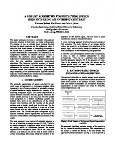
II. NETWORK ARCHITECTURE This section discusses the network architecture of dense femtocell deployment. A. Proposed Network Architecture The network architecture in support of femtocellular network is shown in Figure 1. Different femtocell access points (FAPs) are connected to the femtocell gateway (FGW) using a cable or ISP network. The FGW is used as (i) a concentrator for the FAPs and (ii) a security gateway for the FAPs. There is no direct link between FGW and RNC; hence, communication with the RNC is done through the Core Network (CN). The traffic flow (in and out) in femtocells is managed by the FGW. The FGW receives traffic from various access networks and forwards it to the destination network. A femtocells operator connects femtocell users with other users through an ISP. An agreement is reached between a femtocell operator and an ISP to provide the required bandwidth to the femtocell users. FGW provides FAP’s position and authorised users to the macrocellular BS database server (DBS) via the CN. The RNC and FGW are connected to the user and control plane in the CN as shown in the Figure 1.
CN Control Plane
User Plane
FGW
RNC SLA Framework
ISP Network
Cable/xDSL/fiber
FAP
FAP
Macrocell Base Station Figure 1: Dense femtocellular network connection to the CN.
B. Dense femtocellular network scenario A large number of femtocells deployed within the coverage of macrocell in a dense femtocellular network, as shown in Figure 2. In this case, finding the appropriate FAP for handover in a macrocell-to-femtocell or femtocell-to-femtocell handover is a huge challenge for better handover decision
ISSN: 2180-1843 e-ISSN: 2289-8131 Vol. 8 No. 9 September – December 2016
A Robust Speed-Based Handover Algorithm for Dense Femtocell/Macrocell LTE-A Network and Beyond
[14]. The mobile user equipment (MUE) needs to choose the right FAP among the numerous neighbour FAPs. In the process, much power and overhead will be required by the MUE in scanning multiple FAPs. The large overhead can be attributed to the density of the femtocell, which means that large amount of information need to be broadcasted by the MUE. Whenever the MUE moves within the area covered by the macrocell, many signals are detected from the neighbouring FAPs due to the presence of many femtocells in that area. This causes unnecessary scanning for the handover.
signal is received from that particular femtocell than from a certain macrocell [16]. In closed access mode, the femtocell services can only be accessed by users registered to the femtocell. In other words, closed access femtocells are used privately by homes, offices and small businesses to provide services for the registered users, such as employees, members of the family, business associate and friends [18]. Hybrid access modes allow the general public to access the femtocell service, while given priority to the registered users. Most current deployment of femtocell has the capability to enable users select the type of mode of the femtocell [19]. III. PROPOSED HANDOVER ALGORITHM This section discusses the proposed handover algorithm and the procedure to be carried out before a handover can take place between a femtocell-to-macrocell and macrocell-tofemtocell integrated network for a dense femtocellular network. The following handovers are possible in a femtocell/macrocell integrated network: macrocell-tofemtocell, femtocell-to-macrocell, femtocell-to-femtocell and macrocell-to-macrocell. In femtocell/macrocell integrated system in LTE-A, macrocell-to-femtocell and femtocell-tofemtocell handovers are difficult than femtocell-to-macrocell handover owing to the large target femtocells in the system [17]. In this case, additional effort is required to select the best target femtocells for handover.
Figure 2: Dense femtocellular network scenario.
Hence, efficient handover management algorithm is essential for a dense femtocell-to-macrocell network deployment to reduce the amount of scanning and ultimately the number of handovers. In the traditional macrocellular schemes, the target femtocell lists are based on the received signal strength indicator only [13], which increases the number of target femtocells in that list. Hence, the traditional schemes are ineffective in the dense femto-macrocell network. Our objective in this work is to reduce potential target femtocells as well as to reduce the overall handover in the dense femtocell-to-macrocell network. A network deployment scenario for dense femtocell-macrocell is shown in Figure 2. There is a coordination between FAPs and the macrocellular BS for smooth handover of MUE from macrocell base station (MBS) to a selected FAP and vice versa. C. Femtocell Access Mode Femtocells are usually configured in three access modes as follows: Open access; Closed access; and Hybrid access. In the open access, every user or subscriber of a network can access the femtocell resources without any restriction. This is generally used by public users in the railway stations, shopping malls, airports, restaurants and many others. The users can connect to open access femtocell whenever a higher
A. The Algorithm The proposed handover algorithm is represented by the flowchart shown in Figure 3. In addition to the signal level measurement, speed of the users, capacity and access mode of the femtocells are considered before handover can take place. In macrocell/femtocell-to-femtocell handovers, an MUE is required to choose a suitable HeNB (FAP) among numerous HeNBs (FAPs) candidates. B. Call procedure The serving cell at regular intervals sends measurement request to the UE as shown in Figure 4. Here UE denotes Mobile User Equipment (MUE). The MUE replies with its measurement report from the neighbouring cells. The speed of the MUE, capacity, and the mode of access of the femtocells are additional parameters used to determine whether the handover will take place or not. Whenever the signal received from the serving HeNB/eNB gets below threshold k1, the MUE starts the measuring of Reference Signal Received Powers (RSRP) of the serving base station and the neighbour HeNBs (FAPs) and eNB (MBS). Based on this signal level, the lists of target HeNBs/eNB are sent to the HeNB-GW by the MME as handover (HO) candidate cells. The selection of the target HeNB/eNB is made according to the speed of the user and other aforementioned parameters. Once this is achieved, a request for the HO will be sent to the target HeNB/eNB, which performs admission control and decide whether to accept or reject the user’s call. On accepting the call, a HO response is sent through the associated gateways to the serving eNB/HeNB, which then tells the MUE (with HO command) the end of the HO preparation phase. Finally, the
ISSN: 2180-1843 e-ISSN: 2289-8131 Vol. 8 No. 9 September – December 2016
123
Journal of Telecommunication, Electronic and Computer Engineering
HO execution phase is carried out with data path switching followed by the release of resources at the serving cell [9, 10].
A. New Arriving calls The CAC policy shown in Figure 5 is first checked, if the femtocell coverage is available whenever a new call arrives at the femtocellular coverage area. If the femtocell is available and can be accessed openly, the new call will try to connect to the HeNB. The call is accepted by the HeNB, if the received signal level k2 condition is met and there is available resources in the HeNB. If this condition could not be met, the call checks MBS for it to connect to the MBS. SNIRT,F is the received signal level of the target HeNB. This call will be rejected if the bandwidth βr,m requested is unavailable in the macrocell.
Figure 3: Proposed handover algorithm.
IV. CAC FOR FEMTOCELL/MACROCELL NETWORKS The CAC is used with the proposed algorithm to manage the resources in the system. The admission of various calls into the network is controlled with this CAC. By using CAC, a huge number of calls can be transferred from macrocell to femtocells. The algorithm in Figure 3 is a general algorithm for the three cases or parts discussed below. In the general algorithm, the speed of the user is considered for all cases and it is applicable before applying the CAC scheme. The proposed CAC scheme is divided into three parts: The first part is used to accept newly generated calls, the second part is used to accept the call already communicating with the MBS and the third part is used to accept the call already communicating with the HeNBs. Two threshold levels k1 and k2 of SNIR are used to accept a call into the system. k1 is used as the minimum level of the signal needed to connect a user’s call to HeNB. k2 is higher than k1 and used to lower the unrequired macrocell-to-femtocell handovers. To accept more handover calls to the macrocell, QoS adaptive traffic in [17, 20] is employed. The required bandwidth to accept a call and the minimum bandwidth allocated for a call of nth traffic class are taken to be βr,m and βmin,m respectively. Each nth class calls will release (βr,m – βmin,m) bandwidth to accept a new call into the macrocell. Also, C and Cused represent the total bandwidth of the macrocell and bandwidth used by the existing calls. The remaining unused, Cunused bandwidth of the macrocell is equal to C-Cused.
124
Figure 4: The call procedure for the proposed algorithm.
Figure 5: CAC Policy for newly arriving call.
B. Calls connected with the MBS The CAC policy in Figure 6 shows the calls that are already connected to the MBS. When a signal from HeNB is detected
ISSN: 2180-1843 e-ISSN: 2289-8131 Vol. 8 No. 9 September – December 2016
A Robust Speed-Based Handover Algorithm for Dense Femtocell/Macrocell LTE-A Network and Beyond
by a moving MUE, the CAC policy checks the received signal of the target HeNB. If the signal meets the k2 threshold or if the current received signal level of MBS is less than or equal to signal of the target femtocell, a macrocell call is handover to the femtocell provided the resources are available at the target HeNB.
call, the βmin,m is still unavailable in the MBS. If the target femtocell signal is greater than or equal
Figure 7: CAC policy for call connected initially with HeNBs
Figure 6: CAC policy for call connected initially with MBS
C. Calls connected with the HeNBs The CAC policy for calls initially communicating with the HeNBs is shown in Figure 7. This policy is applicable to femtocell-to-femtocell/macrocell handovers. When a moving MUE notices that its signal level from the source HeNB is low, the MUE based on its speed as in Figure 3, begins a handover process to other femtocells. If the femtocells are not available for handover, the MBS is approached for connection. If the available bandwidth resources in the MBS are insufficient to admit the call, the CAC policy reduces the QoS of existing calls to allow the release of some bandwidth. In addition, the policy permits the bandwidth required by a handover call request to be reduced. The maximum number of bandwidth that can be reduced for a requested handover call on an existing call is (βr,m – βmin,m). Hence, the total call admitted into the system will be increased, while the handover dropping probability is reduced. However, the call will be dropped, if after reducing some bandwidth from the existing
to k2, the MUE will try to handover to target HeNB. However, if it is within k2 and k1 range, the MUE will try to connect with the MBS. If there is no available resource in the macrocell, the QoS degradation policy is not obtainable in the femtocell; thus, MUE tries to handover to the target HeNB even if its received signal is less than k2, provided the target HeNB can be accessed openly. V. THE QUEUING ANALYSIS AND THE TRAFFIC MODEL We have adopted the Markov chain model in [17] for the proposed algorithm as shown in Figure 8 and 9. In the femtocell layer, the states of the system are represented by the number of calls in that system. N is used to represent the maximum number of calls accommodated by the system. Assuming that all calls arriving process follow the Poisson distribution, we define µf and µm as the channel release rates of the femtocell and macrocell respectively. Femtocells are deployed randomly within the macrocell area and can be either open or closed access.
Figure 8: Markov chain for the femtocell layer [17].
ISSN: 2180-1843 e-ISSN: 2289-8131 Vol. 8 No. 9 September – December 2016
125
Journal of Telecommunication, Electronic and Computer Engineering
(λo,m+λh,mm+λh,fm+Pb,fαo,f +αPd,fλh,ff+(1-α)λh,ff
0
(λo,m+λh,mm+λh,fm+Pb,fαo,f
(λo,m+λh,mm+λh,fm+Pb,fαo,f
+αPd,fλh,ff+(1-α)λh,ff
(λo,m+λh,mm+λh,fm+Pb,fαo,f
+αPd,fλh,ff+(1-α)λh,ff
+αPd,fλh,ff+(1-α)λh,ff
X
1
2µm
µm
(X+1)µm
Xµm
X+Y
X+Y-1
(X+Y1)µ
(X+Y)µ
Figure 9: Markov chain for the macrocell layer [17].
As in the femtocell layer, the states of the system are represented by the number of calls. The meaning of symbols used in Figure 8 and Figure 9 are as follows. λo,f/λf,o is the total originated-call arrival rate in the femtocell coverage area and λo,m/λm,o is the total originated-call arrival rate in the macrocell coverage area.
h, ff , h, fm , h,mf
and
λnPb λn(1-Pb) λh
h,mm represent the call rates for
femtocell-to-femtocell, femtocell-to-macrocell, macrocell-tofemtocell and macrocell-to-macrocell handover respectively. femtocell and macrocell. Pd , f , Pd , m represent the dropping probability of handover call in the femtocell and macrocell. Additional states provided by macrocell in supporting handover calls is represented by X and then the number without additional states is represented by Y. The QoS adaptation policy provides the additional state and is used only in the macrocell to accept more handover calls from the femtocell. The macrocell layer average channel release rate increases whenever the number of femtocell deployed increases. This is because more traffic from the macrocell is being handed over to the femtocells as the number of femtocell increases. The average channel release rate can be calculated for both femtocell and macrocell as follows as in [21, 22]. At femtocell layer,
f f
where
n 1
Figure 10: Call rate traffic model.
The handover-call arrival rates have been computed as follows: f ,o 1 Pb , f h ,mf 1 Pd , f h , ff Ph , ff 1 Ph , ff 1 Pd , f 1 Pd , m
h , fm Ph , fm
h, mf Ph, mf
h, mm Ph, mm
f ,o 1 Pb , f h , mf 1 Pd , f
1 , 1 f and 1 m represent the average call
duration, cell dwell time for the femtocell and the macrocell respectively. As shown in Figure 10, the total call rate entering a cell (originating plus handover) is equal to the calls leaving the cell.
1 P b, m
m,o
1 P b, m
m, o
f ,o Pb, f 1 Pd , m h, fm h, ff 1 Pd , f 1 Ph, mf 1 Pd , m
f , o Pb, f 1 Pd , m h, fm h, ff 1 Pd , f 1 Ph, mm 1 Pd , m
probabilities for femtocell-to-femtocell, femtocell-tomacrocell, macrocell-to-femtocell, and macrocell-to-macrocell respectively. The formula for the handover probability has been given as follows: 2 rf f Ph , fm 1 n rm f
Ph , ff
rf n 1 rm
126
1 Ph , ff 1 Pd , f 1 Pd , m
where Ph , ff , Ph , fm , Ph , mf and Ph ,mm are the handover
At macrocell layer,
m m
Cell
λhPd
Pb , f , Pb ,m is the blocking probability of originated-calls in the
µc
λh(1-Pd)
ISSN: 2180-1843 e-ISSN: 2289-8131 Vol. 8 No. 9 September – December 2016
f f 2
A Robust Speed-Based Handover Algorithm for Dense Femtocell/Macrocell LTE-A Network and Beyond
Ph ,mf
rf n rm
m n m n
VI. PERFORMANCE ANALYSIS AND RESULTS
2
The average-call blocking probability Pb , f and the averagecall dropping probability Pd , f in the femtocell have been calculated as follows:
T , F Pf N n N T , F n i 0
N
Pb , f Pd , f
1 N ! Nf i 1 i i! f
where λT,f = λF,0 + λh,mf + αλh,f,f + Pd,mγλh,f, In which the α is the probability that the signal received from the T-HeNB is greater than K2 and γ is the probability that the signal of the T-HeNB is in between k2 and k1. Since the QoS adaptation policy is only applicable to the macrocell handover calls, then, the average-call blocking probability Pb,m and the average-call dropping probability Pd,m are given as follows:
Pb , m
where
X Y
X Y
Pi
iX
h ,m h ,m X
m ,o
i X
i N
i! mi
P0
h,m h, fm Pd , f h, ff 1 h, ff
Table 1 Simulation Assumptions Parameter Radius of the eNB Radius of HeNB Power of eNB Power of HeNB Number of users in a macrocell Initial number of users in a femtocell Mode access of femtocell K1: threshold value K2: threshold value Bandwidth capacity of a macrocell Number of femtocell deployed within macrocell area Average call duration time for all calls UEs Mobility Users traffic model UE Speed Simulation duration
Value 500 m 15 m 46 mW 20 mW 1000 4 Open -80 dBm -60 dBm 10 Mbps the
100 – 1000 150 seconds Random Real and Non real time {3, 25, 60, 150, 300} kmph 100 seconds
X m, h i X Y m,o m,h X m, h i N P0 m,o i! mi i! mi i X 1 i 0 1
To determine the performance of the proposed speed-based algorithm, the algorithm is compared with an existing algorithm in [10] where the speed of the user is not considered. In the existing algorithm, a BS is chosen as the target femtocell or macrocell BS if the signal level received from that femtocell or macrocell BS is greater than or equal to the signal of the MUE from the serving BS. Figure 11 shows the handover probability comparison of the proposed speedbased algorithm and the existing algorithm as a function of new call arrival rate. It can be seen from the graph that the handover probability increases with new call arrival rate. However, the handover probability for the proposed speedbased algorithm is lower than that of the existing algorithm. This can be attributed to the fact that in the proposed speedbased algorithm, high speed users are served by the macrocell, thereby reducing the number of handovers that would have occurred if served by the femtocells. On the other hand, the handover probability is very high in the existing algorithm because the high speed users are served by the femtocells leading to frequent handover from one femtocell to another. In addition, using signal level alone as a condition for handover is not sufficient in a highly dense and highly mobile femtocellular network deployment. The graph of call blocking probability of existing and proposed handover algorithm with respect to new call arrival rate is shown in the Figure 12. It can be seen that the call blocking probability for the existing algorithm is about 0.12 whereas in the proposed algorithm, the blocking probability is around 0.06 at the same call arrival rate of 2 calls/sec. This is due to the fact that in the existing algorithm, calls from the highly mobile users can be connected to any femtocell, which makes the femtocells to be quickly used up and then more calls are dropped. This is because such users cannot stay long in the femtocell owing to the femtocell short distance coverage, and the user’s ability to cover such distance within a few seconds (i.e. the speed covered in km/hr is very high). In the proposed algorithm on the other hand, calls originated from highly mobile users stay connected with macrocell, while the low speed are connected to the femtocells; thus, fewer calls are blocked in the overall system. The same can also be concluded by looking at the rest of the simulation with the proposed algorithm performing better each time. Also, the blocking probability in the existing algorithm can be reduced by almost 50%. This further shows that the proposed algorithm is better and more suitable for a highly mobile user and densely deployed femtocell environment than the existing algorithm. The call dropping probability of the existing and proposed algorithms is shown in Figure 13. As in Figure 13, large call dropping probability is noticed in the existing algorithm compared with the proposed algorithm with reduced dropping probability for all new call arrival rates. For instance, at arrival rate of 2 calls/sec, call dropping probability in the existing system is around 0.035 whereas in the proposed algorithm, the call dropping probability is around 0.005. This means that the proposed algorithm has a significant call dropping probability reduction compared to the existing algorithm.
ISSN: 2180-1843 e-ISSN: 2289-8131 Vol. 8 No. 9 September – December 2016
127
Journal of Telecommunication, Electronic and Computer Engineering
This can be attributed to the fact that in the existing algorithm, the overall system capacity are easily filled up with calls from high mobile users and calls from frequent handover. In the process, more calls are being dropped quickly by the femtocells while the macrocells still have the capacity to accommodate more calls. This leads to high call dropping probability of the whole system and low utilisation of resources. But with the proposed algorithm, macrocell handles most of the calls from the highly mobile users and femtocells handle calls from the low speed users. Thus, the resources of both macrocell and femtocell are being efficiently utilised leading to reduction in call dropping probability.
0.5 0.45 0.4
Handover probability
0.35 0.3 0.25 0.2 0.15 0.1
Existing algorithm Proposed algorithm
0.05 0
0
2
4
6 8 10 12 14 New call arrival rate (calls/sec)
16
18
VII. CONCLUSION AND FUTURE WORK 20
Figure 11: Handover Probability
0.35
0.3
Call blocking probability
0.25
0.2
0.15
0.1
Existing algorithm Proposed algorithm
0.05
0
0
2
4
6 8 10 12 14 New call arrival rate (calls/sec)
16
18
20
Figure 12: Call blocking probability
Dense femtocellular network deployment is a good way to achieve increased coverage and capacity in the present LTEAdvanced and future networks. By overlaying thousands of femtocells within a single macrocell, a large number of traffic can be offloaded from the macrocells to the femtocells. This however, often leads to frequent handover of mobile user equipment from one femtocell to another femtocell. Therefore, to effectively utilise the resources of both macrocell and femtocells, an efficient handover management algorithm is the key issue for successful deployment of dense femtocellular networks. In this work, we have proposed a robust speed-based handover algorithm to address this management issue. In the proposed algorithm, a large number of handovers were reduced by making highly mobile users use the service of macrocell and low speed users to use the services of femtocells. The results obtained in Figure 12 and Figure 13 also show that there is high improvement in terms of blocking and dropping probability with the proposed scheme. In the near future, a real-life deployment of thousands of femtocells overlaid within macrocell will be of interest to the people in the industry. This work has provided a good basis for people in the industry to successfully implement dense femtocellular networks.
0.06
REFERENCES
Call dropping probability
0.05
[1]
0.04 Existing algorithm Proposed algorithm
[2]
0.03
[3]
0.02
0.01
[4] 0
0
2
4
6 8 10 12 14 New call arrival rate (calls/sec)
Figure 13: Call dropping probability
128
16
18
20
[5]
[6]
Y. Mehmood, C. Gorg, M. Muehleisen, and A. Timm-Giel, “Mobile M2M communication architectures, upcoming challenges, applications, and future directions”, EURASIP Journal on Wireless Communications and Networking, pp. 2-37, Nov. 2015. H. A. Salman, L. F. Ibrahim, and Z. Fayed, “Overview of LTEAdvanced Mobile Network Plan Layout,” in Fifth International Conference on Intelligent Systems, Modelling and Simulation, pp. 585590, 2014. H. Wang, M. Wu, W. Li, and J. Wan, “Handover parameter optimization for high-speed railway LTE systems,” Journal of Computational Information Systems, vol. 10, no. 17, pp. 7591-7600, Sept. 2014. 3GPP, “E-UTRA and UTRAN Overall Description,” ETSI TS 136.300 V10.7.0, 2012. F. A. Al-Shahin, “Femtocell-to-Femtocell Handoff management in Dense Femtocellular networks”, International Journal of Computer and Communication Engineering, vol. 4, no. 5, pp. 346-353, Sept. 2015. R. Iyer, J. Zeto, D. Schneider, and L. Kurtz, Small Cells Big Challenge: A Definitive Guide to Designing and Deploying HetNets,1st Ed., CreateSpace Independent Publishing, Feb. 2014.
ISSN: 2180-1843 e-ISSN: 2289-8131 Vol. 8 No. 9 September – December 2016
A Robust Speed-Based Handover Algorithm for Dense Femtocell/Macrocell LTE-A Network and Beyond [7]
[8]
[9]
[10]
[11]
[12]
[13]
[14]
D. Xenakis, N. Passas, L. Merakos, and C. Verikoukis, “Mobility Management for Femtocells in LTE-Advanced: Key Aspects and Survey of Handover Algorithms,” IEEE Communications Surveys and Tutorials, vol. 16, no. 1, pp. 64-91, July 2013. H. S. Jo, P. Xia, and J. Andrews, “Open, closed, and shared access femtocells in the downlink,” EURASIP Journal on Wireless Communications and Networking, pp. 1-16, Dec. 2012. M. Boujelben, S. Rejeb and S. Tabbane, “A Novel Green Handover Self-Optimization Algorithm for LTE-A/5G HetNets,” Proc. of 2015 IEEE International Wireless Communications and Mobile Computing Conference (IWCMC), Dubrovnik, Croatia, 24-28 Aug. 2015, pp. 413418. A. B. Cheikh, M. Ayari, R. Langar, G. Pujolle, and L. A. Saidane, “Optimized Handover Algorithm for Two-Tier Macro-Femto Cellular LTE Networks,” in IEEE 9th International Conference on Wireless and Mobile Computing, Networking and Communications (WiMob), pp 608-613, Oct. 2013. S.A. Mahmud, G.M. Khan, H. Zafar, K. Ahmad, and N. Behttani, “A Survey on Femtocells: Benefits deployment models and proposed solutions,” Elsevier Journal of Applied Research and Technology, vol. 11, no. 5, pp. 733-754, Oct. 2013. F. A. Al-Shahin, “Femtocell-to-Femtocell Handoff management in Dense Femtocellular networks”, International Journal of Computer and Communication Engineering, vol. 4, no. 5, pp. 346-353, Sept. 2015. TFZ Badri, R. Saadane, S. Mbarki and M. Wahbi, “Call Admission Control Scheme and Handover Management in LTE FemtocellMacrocell Integrated Networks,” Computer and Information Science, vol. 8, no. 1, pp. 1-16, Jan. 2015. H. Zhang, W. Ma, W. Li, W. Zheng, X. Wen and C. Jiang, “Signalling Cost Evaluation of Handover Management Schemes in LTE-Advanced
[15]
[16]
[17]
[18]
[19]
[20]
[21] [22]
Femtocell,” Proc. of IEEE Vehicular Technology Conference (VTC Spring), Yokohama, Japan, 15-18 May 2011, pp. 1-5. H. Jo, C. Mun, J. Moon and J. Yook, “Self-Optimized Coverage Coordination in Femtocell networks,” IEEE Transactions on Wireless Communications, vol. 9, no. 10, pp. 2977-2982, Sept. 2010. T. Bai, Y. Wang, Y. Liu and L. Zhang, “A policy-based handover mechanism between femtocell and macrocell for LTE based networks,” Proc. of IEEE International Conference on Communication Technology (ICCT), Jinan, China, 25-28 Sept. 2011, pp. 1-21. M. Z. Chowdhury and Y. M. Jang, “Handover management in highdense femtocellular networks,” EURASIP Journal on Wireless Communications and Networking, pp. 1-21, Jan. 2013. H. Zhang, X. Wen, B. Wang, W. Zheng and Y. Sun, “A Novel Handover Mechanism between Femtocell and Macrocell for LTE Based Networks,” Proc. of IEEE Second International Conference on Communication Software and Networks (ICCSN), Singapore, 26-28 Feb., 2010, pp. 228-231. P. Lin, J. Zhang, Y. Chen, and Q. Zhang, “Macro-femto heterogeneous network deployment and management: from business models to technical solutions,” IEEE Wireless Communications, vol. 18, no. 3, pp. 64-70, June 2011. M. Z. Chowdhury, Y. M. Jang, and Z. J. Haas, “Call Admission Control based on adaptive bandwidth allocation for multi-class services in wireless networks”, Proc. of IEEE International Conference on ICT Convergence (ICTC), Jeju 2010, pp. 358-361. M. Schwartz, Mobile Wireless Communications, Cambridge University Press, United Kingdom, 2005. I. Stoimenovic, Hanbook of Wireless Networks and Mobile Computing, Wiley, New York, 2002.
ISSN: 2180-1843 e-ISSN: 2289-8131 Vol. 8 No. 9 September – December 2016
129