ORS satellite architecture would be developed. Finally, this research also defines
a preliminary system design that would enable satellites to be launched on ...
NAVAL POSTGRADUATE SCHOOL MONTEREY, CALIFORNIA
THESIS A SATELLITE ARCHITECTURE FOR OPERATIONALLY RESPONSIVE SPACE by Jeremy Scott Geib March 2009 Thesis Advisor: Second Reader:
Thomas V. Huynh William J. Welch
Approved for public release; distribution is unlimited
THIS PAGE INTENTIONALLY LEFT BLANK
REPORT DOCUMENTATION PAGE
Form Approved OMB No. 0704-0188
Public reporting burden for this collection of information is estimated to average 1 hour per response, including the time for reviewing instruction, searching existing data sources, gathering and maintaining the data needed, and completing and reviewing the collection of information. Send comments regarding this burden estimate or any other aspect of this collection of information, including suggestions for reducing this burden, to Washington headquarters Services, Directorate for Information Operations and Reports, 1215 Jefferson Davis Highway, Suite 1204, Arlington, VA 22202-4302, and to the Office of Management and Budget, Paperwork Reduction Project (0704-0188) Washington DC 20503.
1. AGENCY USE ONLY (Leave blank)
2. REPORT DATE 3. REPORT TYPE AND DATES COVERED March 2009 Master’s Thesis 4. TITLE AND SUBTITLE A Satellite Architecture for Operationally Responsive 5. FUNDING NUMBERS Space 6. AUTHOR(S) Jeremy Scott Geib 7. PERFORMING ORGANIZATION NAME(S) AND ADDRESS(ES) Naval Postgraduate School Monterey, CA 93943-5000 9. SPONSORING /MONITORING AGENCY NAME(S) AND ADDRESS(ES) N/A
8. PERFORMING ORGANIZATION REPORT NUMBER 10. SPONSORING/MONITORING AGENCY REPORT NUMBER
11. SUPPLEMENTARY NOTES The views expressed in this thesis are those of the author and do not reflect the official policy or position of the Department of Defense or the U.S. Government. 12a. DISTRIBUTION / AVAILABILITY STATEMENT 12b. DISTRIBUTION CODE Approved for public release; distribution is unlimited 13. ABSTRACT (maximum 200 words)
Operationally Responsive Space (ORS) is focused on putting satellites in orbit in significantly less time than it currently takes. ORS is based on responding to an operational need quickly, but it should not be thought of as a new way to place national systems in orbit. Operational needs likely result from a need to augment an existing system or to replace a portion of an existing system. Whether a satellite is required as an augmentation or a replacement, it would need to be placed in orbit on the order of weeks, not years, as it would take to deploy a satellite from scratch. ORS systems will be a gap filler aimed at maintaining an existing advantage in unforeseen circumstances. This research shows, based on the available literature, how the needs for ORS can be broken down systematically into a set of requirements to be used to design a space system. It provides a basic concept of how an ORS satellite architecture would be developed. Finally, this research also defines a preliminary system design that would enable satellites to be launched on short notice.
14. SUBJECT TERMS ORS
17. SECURITY CLASSIFICATION OF REPORT Unclassified
15. NUMBER OF PAGES 67 16. PRICE CODE 18. SECURITY CLASSIFICATION OF THIS PAGE Unclassified
NSN 7540-01-280-5500
19. SECURITY 20. LIMITATION OF CLASSIFICATION OF ABSTRACT ABSTRACT Unclassified UU Standard Form 298 (Rev. 2-89) Prescribed by ANSI Std. 239-18
i
THIS PAGE INTENTIONALLY LEFT BLANK
ii
Approved for public release; distribution is unlimited
A SATELLITE ARCHITECTURE FOR OPERATIONALLY RESPONSIVE SPACE Jeremy S. Geib Captain, United States Air Force B.S., Naval Postgraduate School, 2008
Submitted in partial fulfillment of the requirements for the degree of
MASTER OF SCIENCE IN SYSTEMS ENGINEERING
from the
NAVAL POSTGRADUATE SCHOOL March 2009
Author:
Jeremy Scott Geib
Approved by:
Thomas V. Huynh Thesis Advisor
William J. Welch Second Reader
David H. Olwell Chairman, Department of Systems Engineering
iii
THIS PAGE INTENTIONALLY LEFT BLANK
iv
ABSTRACT
Operationally Responsive Space (ORS) is focused on putting satellites in orbit in significantly less time than it currently takes.
ORS is based on responding to an
operational need quickly, but it should not be thought of as a new way to place national systems in orbit. Operational needs likely result from a need to augment an existing system or to replace a portion of an existing system. Whether a satellite is required as an augmentation or a replacement, it would need to be placed in orbit on the order of weeks, not years, as it would take to deploy a satellite from scratch. ORS systems will be a gap filler aimed at maintaining an existing advantage in unforeseen circumstances. This research shows, based on the available literature, how the needs for ORS can be broken down systematically into a set of requirements to be used to design a space system. It provides a basic concept of how an ORS satellite architecture would be developed. Finally, this research also defines a preliminary system design that would enable satellites to be launched on short notice.
v
THIS PAGE INTENTIONALLY LEFT BLANK
vi
TABLE OF CONTENTS
I.
INTRODUCTION........................................................................................................1 A. BACKGROUND ..............................................................................................1 B. PURPOSE.........................................................................................................2 C. RESEARCH QUESTIONS .............................................................................2 D. BENEFITS OF STUDY...................................................................................2 E. SCOPE & METHODOLOGY........................................................................3
II.
OPERATIONALLY RESPONSIVE SPACE............................................................5 A. INTRODUCTION............................................................................................5 B. OPERATIONAL CONCEPT .........................................................................6 C. NEED FOR ORS..............................................................................................7 D. CHAPTER SUMMARY..................................................................................9
III.
PAYLOAD DESIGN .................................................................................................11 A. INTRODUCTION..........................................................................................11 B. PAYLOAD DESIGN .....................................................................................12 1. Visible Imaging Satellite....................................................................12 2. Broadcast Communication Satellite.................................................16 3. Two-way Communication Satellite ..................................................20 C. PAYLOAD REQUIREMENTS....................................................................22 1. Shared Requirements: .......................................................................22 2. Visible Imager Requirements: ..........................................................23 3. Infrared Imager Requirements: .......................................................23 4. Broadcast Communications Requirements:....................................23 5. Two-Way Communications Requirements: ....................................23 D. CHAPTER SUMMARY................................................................................24
IV.
SPACECRAFT BUS DESIGN..................................................................................25 A. INTRODUCTION..........................................................................................25 B. SATELLITE BUS CHARACTERISTICS ..................................................25 C. SPACECRAFT BUS REQUIREMENTS ....................................................38 1. Spacecraft Bus Requirements:..........................................................38 2. Propulsion Requirements:.................................................................38 3. ADACS Requirements: .....................................................................38 4. Communications Subsystem Requirements:...................................38 5. Command and Data Handling Subsystem Requirements: ............39 6. Thermal Subsystem Requirements: .................................................39 7. Electrical Subsystem Requirements:................................................39 8. Structural Subsystem Requirements: ..............................................39
V.
COST ESTIMATES ..................................................................................................41 A. INTRODUCTION..........................................................................................41 B. SPACE VEHICLE COST .............................................................................41 C. CHAPTER SUMMARY................................................................................45 vii
VI.
APPLICATION OF STUDY ....................................................................................47 A. INTRODUCTION..........................................................................................47 B. RECOMMENDATIONS...............................................................................47 C. AREAS FOR FURTHER RESEARCH.......................................................48
LIST OF REFERENCES ......................................................................................................49 INITIAL DISTRIBUTION LIST .........................................................................................51
viii
LIST OF FIGURES Figure 1. Figure 2.
Satellite top-level system breakdown ..............................................................11 Spacecraft bus subsystem functional breakdown ............................................25
ix
THIS PAGE INTENTIONALLY LEFT BLANK
x
LIST OF TABLES Table 1. Table 2. Table 3. Table 4. Table 5. Table 6. Table 7. Table 8. Table 9. Table 10. Table 11. Table 12. Table 13. Table 14. Table 15. Table 16. Table 17. Table 18. Table 19. Table 20. Table 21. Table 22. Table 23. Table 24. Table 25. Table 26. Table 27. Table 28.
Initial visible sensor estimates .........................................................................14 IR payload characteristics ................................................................................15 Initial infrared sensor estimates .......................................................................16 Broadcast comm. payload uplink link budget..................................................18 Broadcast communication payload downlink link budget...............................19 Two way communication payload uplink link budget.....................................21 Two way communication payload downlink link budget................................22 Initial satellite power estimates........................................................................26 Initial satellite mass estimates..........................................................................26 ADACS mass and power estimates .................................................................29 Bus communication subsystem uplink link budget .........................................30 Bus communication subsystem downlink link budget.....................................30 Updated satellite power estimates....................................................................34 Updated satellite mass estimates......................................................................34 Update power subsystem characteristics .........................................................35 Updated propellant mass..................................................................................36 Updated structural mass...................................................................................36 Updated satellite power estimates....................................................................37 Updated satellite mass estimates......................................................................37 Propulsion subsystem cost ...............................................................................41 Attitude determination and control subsystem cost .........................................42 Communication subsystem cost.......................................................................42 Commanding & data handling subsystem cost................................................42 Thermal control subsystem cost.......................................................................43 Power subsystem cost ......................................................................................43 Structural subsystem cost.................................................................................43 Satellite cost estimates .....................................................................................44 Cost estimation uncertainty .............................................................................44
xi
THIS PAGE INTENTIONALLY LEFT BLANK
xii
ACKNOWLEDGMENTS
First, thank you to the professors I’ve interacted with these last few years. Next a big thank you to my team who kept things running while I was in class every Friday and for the work they did the rest of the time as well. Of course another thank you to Mr. Leonard, for multiple reasons but in this case allowing me to take those days off and the general support to my pursuit of this degree. To my mother and grandmothers, you have made me the person I am today. Most importantly for my wife, Leticia, even when I was locking myself to the computer on evenings and weekends you were and still remain my biggest supporter.
xiii
THIS PAGE INTENTIONALLY LEFT BLANK
xiv
I.
A.
INTRODUCTION
BACKGROUND Operationally Responsive Space (ORS) is focused on placing satellites in orbit in
significantly less time than it currently takes. This is based on responding to an operational need quickly, but it should not be thought of as a new way to place national systems in orbit. To be effective, ORS must include planning for the ground segment and the launch vehicle as well as the satellite itself; however, this thesis focuses on the satellite portion of ORS. Operational requirements likely result from a need either to augment an existing system or to replace a portion of an existing system. A need for more capacity in a certain area by, for example, the Joint Forces Commander would require the augmentation. A replacement of a satellite would be needed if the satellite failed as a result of either an unexpected cause or a direct act by an adversary. Whether a satellite is required as an augmentation or a replacement, it would need to be placed on orbit on the order of weeks ─ not years as it would take to deploy a satellite from scratch. ORS systems will be neither the required full-scale national systems nor the cutting edge systems used to gain an advantage against the U.S.’s adversaries. Rather, ORS systems will be a gap filler aimed at maintaining an existing advantage in unforeseen circumstances. Cutting satellite development time from years to weeks may be the most challenging aspect of ORS. It is, however, not the only aspect. A launch system must be in place to launch ORS satellites into orbit in a short amount of time. Furthermore, a system must be in place to command and control the satellites once on orbit. The command and control system would have to include the operational procedures and, much more importantly, trained personnel who know how to operate the satellites.
1
B.
PURPOSE This research shows, based on the available literature, how the needs for ORS can
be broken down systematically into a set of requirements to be used to design a space system. It provides a basic concept of how an ORS satellite architecture would be developed. In other words, it answers the question as to what would be the requirements for a system of satellites that were designed for operationally responsive space. This research also defines a rough system design that would enable satellites to be launched on short notice. C.
RESEARCH QUESTIONS This research primarily attempts to answer the question: What would the design
of an Operationally Responsive Space satellite look like? In order to answer this question the following six questions will be addressed. •
What is Operationally Responsive Space?
•
Why is Operationally Responsive Space needed?
•
How might Operationally Responsive Space be used?
•
What changes in satellite design and development methodology will be needed for Operationally Responsive Space?
•
What types of satellite payloads would be used in Operationally Responsive Space?
•
What would be the likely capabilities for satellites in Operationally Responsive Space?
Answering these questions leads to a conceptual design for an ORS satellite architecture. D.
BENEFITS OF STUDY This study provides a framework in which the Air Force and Department of
Defense can develop satellite architecture for use in designing Operationally Responsive Space systems.
2
E.
SCOPE & METHODOLOGY This thesis focuses on the satellite architecture needed for Operationally
Responsive Space. This thesis analyzes the available literature on ORS and use the resulting information to establish the requirements for ORS systems. These requirements are then used in the derivation of a preliminary design for a set of ORS satellites.
3
THIS PAGE INTENTIONALLY LEFT BLANK
4
II.
A.
OPERATIONALLY RESPONSIVE SPACE
INTRODUCTION What is Operationally Responsive Space (ORS)? Many definitions of ORS exist
within the DoD. The DoD Plan for Operationally Responsive Space, as set forth to Congress by Ronald M. Sega and General James E. Cartwright, considers ORS as: “a subset of space activities designed to satisfy Joint Force Commanders’ (JFC) needs, while maintaining the ability to address other users’ needs for improving the responsiveness of space capabilities to meet national security requirements” (Sega and Cartwright, 2007). The needs of the JFCs are thus the sole focus of the operational part of ORS. The responsive portion of ORS is a need shared by the JFC and national security. The reasons for sharing are that the DoD relies on space capabilities and that, in future wars, an adversary would likely attempt to attack U.S. space assets or to use existing commercial assets in an attack against the U.S.
In light of this shared need, the
commander of USSTRATCOM has three desires for ORS (Sega and Cartwright, 2007). •
Rapidly exploit and infuse space technological or operational innovations.
•
Rapidly adapt or augment existing space capabilities when needed to expand operational capability.
•
Rapidly reconstitute or replenish space capabilities to preserve operational capability.
The first desire ensures that adversaries using existing commercial systems will have less capability than the U.S. does. The use of ORS as a space test bed will help improve the strategic side of the national space acquisition process by allowing experimental technologies to be fielded and tested on cheaper ORS systems before being incorporated into expensive national strategic assets. The second desire is directly related to meeting the JFCs needs of placing additional capability in needed locations either by on-orbit repositioning or by launching additional satellites. The third desire is focused on
5
recovery in the event an adversary’s attempts to deny U.S. forces the space capabilities to which they have become accustomed. In this regard, ORS serves the needs of both the JFCs and the strategic users. To meet these desires, the DoD and the intelligence community will take a threetiered approach to enhancing the responsiveness of space capabilities. The first tier involves using the existing on-orbit capabilities by simply reprioritizing a satellite’s use or by carrying out the complicated task of changing a satellite’s orbit. Tier 1 solutions would be expected to take effect within a few days after the need is established. Tier 2 solutions involve augmenting the existing capabilities, generally by launching low-cost satellites that have already passed the majority of their integration and testing. The second-tier solutions would be expected to be available within weeks of a verifiable need. Tier 3 solutions involve the development of new capabilities. The responsiveness aspect of ORS requires such a development to be quicker than the current timelines for placing capabilities on orbit. Tier 3 solutions could take up to a year to meet the need. B.
OPERATIONAL CONCEPT The operational concept associated with the Tier 1 solutions is similar to the
baseline use for any operational asset, with the additional complications of a space environment. Tier 2, however, requires some new concepts regarding building and placing satellites on orbit. Tier 3 would build on the concepts developed for Tier 2. Required to minimize the development work, Tier 3, like Tier 2, requires large amounts of prior development and satellite building. Tier 1 solutions are primarily a matter of balancing resources.
Instead of
performing its normal responsibilities, a capability is either reprioritized to suit the needs of the JFCs or reprioritized and moved by changing the orbital characteristics of the satellite. Reprioritization requires the proper policies and the decision making process to be in place ahead of time and could involve terrestrial as well as space based modifications.
Moving a satellite may not be simple; however, procedures to perform
satellite maneuvers exist for most operational satellite constellations. 6
Tier 2 solutions signify the revolutionary portion of ORS, which would require at least partially built satellites to be quickly integrated and placed on a launch vehicle to achieve orbit.
Once on orbit, they would be quickly checked out and placed into
operational use. One possible way to enable a quick launching of satellites would involve having a standardized bus to which various payloads could be attached in a plugand-play concept. A standardized bus is desired to reduce both development cost as well as minimizing storage and extra production costs. The standardized bus would contain the core subsystems needed to sustain the payload, such as power generation, thermal control, electrical power, propulsion, communication, and structural and launch vehicle interface (Brown, 2004). Tier 3 is an expansion of Tier 2. Most of the design work would be complete, but some modification might be necessary. The standardized bus would be used, but a design change on the payload could occur. Similar to Tier 2, Tier 3 will require some paradigm shifts on how satellites are traditionally designed, built, and launched from the current small production runs to an assembly line type process similar to what was used for Iridium. C.
NEED FOR ORS The need for ORS is precipitated by an increasing use of and dependence on
space-based assets by the U.S. military. In Desert Storm, 542,000 military members had 99 megabits per second available for use; by the time of Operation Iraqi Freedom (OIF) ten years later, 350,000 personnel generated a throughput of 3,200 megabits per second (Cebrowski and Raymond, 2005). In Desert Storm, GPS was used to navigate in the desert; 10 years later in OIF, GPS was used to place 5,500 Joint Direct Attack Munitions (JDAMS) within 10 feet of their target (GPS Fact Sheet, 2007). In addition, the use of imagery and missile warning data has dramatically increased (Cebrowski and Raymond, 2005). This increased use has led to an increased need for imagery and missile warning capability as well as an increased usage of the communication satellites that transmit this data.
7
The need for ORS can be realized in one of two forms ─ augmentation and reconstitution (Sega and Cartwright, 2007).
Augmentation means adding additional
capability to what is already on orbit, generally based on the needs of a JFC. Reconstitution means quickly replacing a lost capability caused by an unexpected satellite failure or an adversary’s hostile actions. Augmentation is driven by the needs of a JFC. Planning for Desert Storm, in September 1990, indicated that a communication satellite was needed to provide additional satellite communication capability. Yet, not until February 11, 1992, over a year and a half later, was a DSCS III satellite then placed in orbit (Brown, 2004). In the future with ORS, additional capacity could be realized without having to depend on commercial systems as it was in the case of Desert Storm. Reconstitution may not be replenishment in kind, but it could provide reduced capabilities for national and military leaders in the event an on-orbit asset is no longer available (Cebrowski and Raymond, 2005).
In the absence of adversary actions, a
satellite may stop operating for many reasons.
A design error or hardware flaw,
undetected through ground testing, could adversely affect the satellite on orbit. The satellite could be damaged by space debris or space weather. Recognizing the U.S. military’s dependence on space systems, an adversary, at some point, will likely attempt to deprive the U.S. military of its space systems. Threats from adversaries to the U.S. satellites can come in many of the following forms (ORS Mission Needs Statement AFSPC 001-01): •
Counterspace forces: Physical threats to space systems and operations, such as directed energy, kinetic energy, jamming, and sabotage against ground assets.
•
Espionage: Information collection efforts targeting national security assets and space systems operations, technologies, manufacturing processes, and logistical networks.
•
Sabotage: Physical threats to space systems payloads, fuels, spacecraft production facilities, transportation, ground operations, software, and command and control facilities.
•
Information Warfare: Information attacks against military space systems communications links and relays. 8
•
D.
Nuclear Forces: Immediate effects from a nuclear weapon detonated in orbit as well as the resulting increase in background radiation.
CHAPTER SUMMARY The increasing dependence of the United States on its space assets at both
operational and strategic levels dictates that the U.S. must develop means to maintain the space capability in times of conflict. To this end, the U.S. must have the ability to rapidly place capability on orbit to either augment or reconstitute existing capability. This ability will require pre-designed satellites and pre-built components that can be quickly integrated and then integrated onto a launch vehicle. The next chapter discusses the design of those satellites.
9
THIS PAGE INTENTIONALLY LEFT BLANK
10
III.
A.
PAYLOAD DESIGN
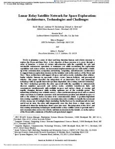
INTRODUCTION A satellite is a complex system that is composed of many interacting subsystems
and components.
To facilitate the design process, it needs to be decomposed into
subsystems (Ulrich and Eppenger, 2000). Satellites are generally divided into two main systems: the payload and the spacecraft bus.
Satellite
Spacecraft Bus
Figure 1.
Payload
Satellite top-level system breakdown
An ORS satellite would have some top-level requirements that are independent of the mission it will be performing. First, its weight must be less than 1000 kg (Cebrowski and Raymond, 2005), as a satellite’s size is a significant contributor to the cost (and complexity) of both the satellite as well as the eventual launch options. Second, mature technologies must be used to build it. For example, improved miniaturization capability, which does not yet exists, is needed in order to achieve the required weight. Finally, it must cost less than current satellites. An estimated cost of less than $15M per satellite for design and development is the defined cost constraint goal within this thesis. This nominal cost was selected as it is representative of current small satellite development programs. 11
B.
PAYLOAD DESIGN ORS will initially focus on the development and deployment of intelligence,
surveillance, and reconnaissance, as well as communication capabilities (Sega and Cartwright, 2007). This thesis will focus on designing four satellites: one visible imaging satellite, one thermal imaging satellite, one broadcast communication satellite, and one two-way communication satellite. All four payloads will use the same satellite bus design. 1.
Visible Imaging Satellite
The visible imaging satellite would need to have a resolution of at least 2 m; a 1m resolution would be preferred, but, because of cost constraints, it may not be achievable. With a 2 m ground resolution it would have a NIIRS (National Imagery Interpretability Rating Scale) value of 4 allowing it to identify by type large fighters for example, but it would not necessarily be able to identify by type deployed tactical SSM systems that it would be able to with a 1 m resolution and a NIIRS value of 5. This is because the resolution is a significant driver to both cost and weight. The desired ground resolution drives the optics aperture diameter and focal length and thus the overall size. The satellite is assumed to be placed in a circular orbit of a 450-km attitude ( H ) that allows a revisit period of 3 days and at a 30 o elevation angle ( EA ). A 550-nm wavelength ( λ ) is selected.
The orbital period of the satellite ( P ) of 93.59 min is then obtained
from P = 1.658669 e − 4( R⊕ + H ) 3 / 2 ,
(1)
in which the eccentricity, e, is zero (for a circular orbit) and the radius of the earth, R⊕ , is
6,378.14 km. The ground speed of the satellite ( V g ) of 7.14 km / s is obtained from V g = 2π
R⊕ P
.
The angular radius of the Earth ( ρ ) is 69.08 o , obtained from 12
(2)
⎛
R⊕ ⎝ R⊕ + H
ρ = sin −1 ⎜⎜
⎞ ⎟. ⎟ ⎠
(3)
The nadir angle ( η ) of 53.99 o is obtained from η = sin −1 [cos(EA ) sin ρ ] ,
(4)
from which the earth central angle ( ECA ) is 6.01o , obtained from ECA = 90 o − η − EA .
(5)
The swath width, which is twice the earth central angle, is then 12.02 o . The slant range ( Rs ) of 825.56 km is obtained from Rs = R⊕
sin (ECA) . sinη
(6)
Assuming a pixel size ( s p ) of 5 × 10 −6 m, the quality factor Q of 1.125 is obtained according to Q=
5 × 10 −3 H f ⋅ Re s
(7)
where Res and f are, respectively, the 2-m resolution and the 1-m focal length. The angular resolution ( Δθ ) of 4.44 × 10 −6 rad is obtained from
Δθ =
Re s . 1000 H
(8)
The number of pixels ( N p ) of 376947 is obtained from
Np =
2ηπ . 180Q
(9)
Assuming 8 bits/pixel, the data rate ( DR ) of 9.57 × 10 9 bps is obtained from DR =
8 N pVg Re s ⋅ Q
13
.
(10)
If the duty cycle is assumed to be 10%, then the amount of data produced ( DP ) in 24 hours is 1378 Gb, calculated according to
DP = 144 DR .
(11)
With 8 contacts a day, 15 minutes per contact, the download data rate ( DDR ) of 191 Mbps is obtained from
DDR =
DP . 7200
(12)
Assuming no more than 6 hours between contacts, the required storage capacity ( Str ) is 345 Gb, obtained from Str =
DP . 4
(13)
The aperture diameter ( dia ) of 0.302 m is then obtained from dia =
2440 λh . Re s
(14)
To estimate the size, weight, and power requirements, a scaling factor determined by the aperture diameter ratio of 0.302 is applied to an existing system. For the purposes of this calculation, the Multi-Spectral Mid-IR sensor (SMAD) is chosen as the existing system. The ratio is cubed when calculating mass and power, and, because the ratio is less than 0.5, a doubling factor is used to provide additional margin on the initial estimates of mass and power. The characteristics of the IR sensor from SMAD and the new visible sensor are shown in Table 1. Table 1. Sensor
Initial visible sensor estimates Scaling factor
Multi-Spectral Mid-IR
Aperture Diameter (m)
0.302
1.0
0.30
Length (m)
0.302
1.5
0.45
Diameter (m)
0.302
1.0
0.30
14
New Visible
Mass (kg)
0.05509
800
44
Max Power (W)
0.05509
900
49.6
The elevation angle and the orbital of the thermal imaging payload are identical to those of the visible imaging payload. The increased complexity and cost lead to a required resolution of 5 m at nadir. This gives it an IR NIIRS value of 2 allowing it to detect the presence of large aircraft but not identify them like the visible sensor is able to. With a 450-km altitude, a 5-m resolution at nadir, a wavelength of 1.7 × 10 −6 m, a pixel size of 5 × 10 −6 m, 8 bits/pixel, a 10% duty cycle, 815-min contacts a day, 6 hours between contacts, the expressions in (1-14) then yield the following characteristics of the infrared payload: Table 2.
IR payload characteristics
Characteristic
Value
Period (min)
93.59
Ground Velocity (km/s)
7.14
Angular radius of earth (deg)
69.08
Nadir angle (deg)
53.99
Earth central Angle (deg)
6.01
Slant Range (km)
825.56
Swath Width (deg)
12.02
Quality Factor
1.125 1.11 x10⁻⁵
Angular Resolution (rad) Number of Pixels
376947
Data Rate (bps)
9.7x10⁹
15
Data Produced (Gb)
1378
Download Data Rate (Mbps)
191
Storage Capacity (Gb)
345
Aperture Diameter (m)
0.373
It is the diameter that marks the difference between the visible payload and the Infrared payload. Table 3 shows a comparison of the initial mid-infrared sensor estimates to those of the multi-spectral mid-IR sensor. Table 3. Sensor
2.
Initial infrared sensor estimates Scaling factor
Multi-Spectral
Mid-IR
Aperture Diameter (m)
0.373
1.0
0.37
Length (m)
0.373
1.5
0.56
Diameter (m)
0.373
1.0
0.37
Mass (kg)
0.104
800
83.2
Max Power (W)
0.104
900
93.7
Broadcast Communication Satellite
For the broadcast communication satellite, the injection points will have 10 W of output power, a 5-m antenna diameter, and receivers have a 0.35-m antenna. Two things drive the orbit decision, the first is because we are using a common bus, the orbital parameters for the communication satellite should be similar to the orbit of the imaging satellites, and the second is because the lower orbit requires less power (and smaller bus size) to close the satellite link. It is placed in a circular orbit at 450-km above the earth; however, this satellite will likely be used in an elliptical orbit so as to maximize the time 16
that it is over the JFC’s area of interest. The uplink frequency will be near 1.8 GHz as this is a commonly used communications frequency with a data rate of 96 Mbps. The uplink link budget is based on the satellite’s receiving antenna with a 1-m diameter ( D ) and a 5 o pointing error. The link budget is now calculated. The peak antenna gain (ground) ( G peak ) of 36.90 db is obtained from G peak =
10 log( π 2 D 2 eff )
λ2
.
(15)
in which a standard efficiency ( eff ) of 55% is used and the wavelength, λ , is 0.167 m. Assuming 3-db line loss, the equivalent isotropically radiated power (EIRP) of 43.90 db is obtained from EIRP= G peak + Lloss + Pout As
above,
it
follows
from
(3),
(16) (4),
and
(5)
that ρ = 69.08 o ,
yields η = 68.52° (corresponding to EA = 5° ), and ECA = 14.48° , respectively. The propagation path length ( L p ) is, by virtue of (6), 1944.48 km, from which space loss ( Ls ) is found to be 163.33 db, obtained from ⎛ λ Ls = 10 log⎜⎜ ⎝ 4000πLP
2
⎞ ⎟⎟ . ⎠
(17)
Atmospheric attenuation (Attatm) is -0.99db obtained from Attatm= -0.06/sin5 - 0.3
(18)
where 0.06 db is the zenith attenuation corresponding to frequencies less than 10 Ghz and 0.3 accounts for polarization mismatches. The peak antenna gain (SV) of 22.92 db is obtained from G peakSV = 10 ⋅ log( π 2 D 2 eff ) / λ 2
(19)
From System Mission Analysis and Design 3rd ed., Table 13-10, the system noise temperature of 614 K results in a G/T of -4.97db using
17
G/T= G peakSV − 10 log T
(20)
where G/T is the gain to temperature ratio. The ground half-power beam width (θ3g) where the output power has dropped to one half of the peak value is 2.33°, obtained from θ3g= 21 /( fD)
(21)
An assumed pointing error (θe) of 1° results in a ground antenna pointing loss of 2.2 db, calculated according to Lpoint=-12(θe/ θ3g)2.
(22)
The space half-power beam width is 11.67° using. (21), from which the space antenna pointing loss is -2.20db using (22). It then follows that Eb/No is 18.98 db, obtained from Eb/No =EIRP + LSpace + Latm+ G/T + Lpoint- 10 log k − 10 log f
(23)
and C/No of 98.8 db is obtained from C/No =Eb/No + 10 log DR .
(24).
The link budget is summarized in Table 4. The margin should be at least 3 db to guarantee reception in most circumstances. Table 4.
Broadcast comm. payload uplink link budget
EIRP (db)
43.90
Space Loss (db)
-163.33
Atmospheric Attenuation (db)
-0.99
G/T (db)
-4.97
Antenna Pointing Losses (db)
-4.41
Eb/No (db)
18.98
C/No (db)
98.80 18
Implementation Loss (db)
-2.00
Margin (db)
7.38
The downlink link budget calculation follows. The downlink frequency will be 2 GHz with a data rate of 96 Mbps. The satellite transmitter will be capable of outputting 200W. The downlink link budget is based on the satellite’s receiving antenna with a 1-m diameter ( D ) and a 5° pointing error. Using these characteristics and (1-24), the link budget is calculated and summarized in Table 5. Again, the margin should be at least 3 db to guarantee reception in most circumstances.
Table 5.
Broadcast communication payload downlink link budget
EIRP (db)
43.84
Space Loss (db)
-164.24
Atmospheric Attenuation (db)
-0.99
G/T (db)
-6.59
Antenna Pointing Losses (db)
-3.05
Eb/No (db)
17.74
C/No (db)
97.56
Implementation Loss (db)
-2.00
Margin (db)
6.14
The mass of the payload is estimated from the calculated masses of the transmitter and two antennas. Since both antennas are 1-m in diameter, their mass (M) are estimated to be 8.1 kg according to 19
M = 10.25πr 2
(25)
where the value 10.25 accounts for the material and shape of the antenna. For a traveling wave tube amplifier transmitter, the mass (M) of 11.4 kg is obtained from M = 10 0.305 +0.135 log P +0.084(log P )
2
(26)
where P is the output power. Similarly, the input power (Pi) of 308 W is obtained from Pi = 10 1.002 +0.236 log P +0.178(log P )
3.
2
(27)
Two-way Communication Satellite
The 2-way communication satellite will assume that the receiving ground terminals are capable of 110 W of output power with a 1-m antenna diameter; a receiving ground terminal would be more likely to be mounted on a vehicle. The link budget calculations assume the satellite is in a circular orbit of 450-km altitude; however, the satellite would more likely be placed in an eccentric orbit in order to maximize its time spent over the JFCs area of interest. The uplink frequency will be 1.8 GHz with a data rate of 96 Mbps. The uplink link budget is based on the satellite’s receiving antenna with a 1-m diameter ( D ) and a 5° pointing error. Using these characteristics and (15-24), the link budget is calculated and summarized in Table 6.
20
Table 6.
Two way communication payload uplink link budget
EIRP (db)
40.33
Space Loss (db)
-163.33
Atmospheric Attenuation (db)
-0.99
G/T (db)
-4.97
Antenna Pointing Losses (db)
-4.41
Eb/No (db)
15.41
C/No (db)
95.24
Implementation Loss (db)
-2.00
Margin (db)
3.81
The downlink link budget is based on the satellite transmitting antenna of a 1-m diameter with a pointing error of 5 o . The downlink frequency is 2 GHz with a data rate of 96 Mbps. The satellite transmitter is capable of outputting 200 W. Using these characteristics and (15-24), the link budget is calculated and summarized in Table 7.
21
Table 7.
Two way communication payload downlink link budget
EIRP (db) Space Loss (db)
37.82 -164.24
Atmospheric Attenuation (db)
-0.99
G/T (db)
2.53
Antenna Pointing Losses (db)
-5.44
Eb/No (db)
18.45
C/No (db)
98.27
Implementation Loss (db)
-2.00
Margin (db)
6.85
The mass of the payload is computed using the estimated masses of the transmitter and the two antennas. It follows from (25) and (26) that the masses of the antenna and the amplifier are, respectively, 8 kg and 6 kg. An input power of 82.6 W is obtained from (27). C.
PAYLOAD REQUIREMENTS
Payloads are to be integrated with the modular bus. Following are the top-level requirements for the payloads. They are the initial payload requirements, which are to be adjusted as the design of the payload matures. 1.
Shared Requirements:
(PL-1) The payload subsystem shall weigh less than 90 kg. (PL-2) The payload subsystem shall require no more than an average of 308 W over a 24-hr period. (PL-3) The payload subsystem shall require a maximum power of 308 W. 22
(PL-4) The payload shall have an on orbit life expectancy of 6 months. (PL-5) The payload shall use a command format as specified in the Spacecraft – Payload Interface Control Document. 2.
Visible Imager Requirements:
(PLVI-1) The payload at a 450-km attitude shall provide a minimum ground resolution of 2 meters. (PLVI-2) The imaging data shall be formatted in accordance with the Spacecraft – Payload Interface Control Document 3.
Infrared Imager Requirements:
(PLIR-1) The payload at a 450-km attitude shall provide at minimum ground resolution of 5 meters. (PLIR-2) The imaging data shall be formatted in accordance with the Spacecraft – Payload Interface Control Document 4.
Broadcast Communications Requirements:
(PLBC-1) The payload shall provide a capability to broadcast 96 Mbps. (PLBC-2) The payload shall provide more than 3 db to a ground receiver with a 0.35m antenna located 1950 km from the satellite and an elevation angle of 5 degrees. (PLBC-3) The payload shall meet all applicable requirements as specified in the National Telecommunications and Information Administration manual of Regulations and Procedures for Federal Radio Frequency Management. 5.
Two-Way Communications Requirements:
(PLTW-1) The payload shall provide a capability to transfer 96 Mbps between any two points within a relative 5 o elevation angle from its location.
23
(PLTW-2) The payload shall provide more than 3 db to a ground receiver with a 1-m antenna located 1950 km from the satellite and at an elevation angle of 5 degrees. (PLTW-3) The payload shall meet all applicable requirements as specified in the National Telecommunications and Information Administration manual of Regulations and Procedures for Federal Radio Frequency Management D.
CHAPTER SUMMARY
This chapter discusses the preliminary design of the four interchangeable payloads ― visible imager, infrared imager, broadcast communications, and two-way communications ― and the determination of some top-level requirements on the payload capabilities. The requirements that will drive the bus design are PL-1, PL-2 and PL-3. PL-1 is the maximum size a PL can be and is from the IR imager (Table 3) with a small margin added. PL-2 and PL-3 are from the broadcast communication payload (27) and are the same because at this stage the satellite is assumed to always be broadcasting. The next section discusses the design a spacecraft bus that can support any four of these payloads.
24
IV.
A.
SPACECRAFT BUS DESIGN
INTRODUCTION
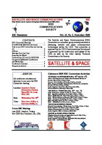
A satellite bus consists of all the subsystems that enable a payload to perform a mission. The subsystems vary among satellites. In this work, for illustrative purposes, the bus consists of the following subsystems: attitude determination and control, structures, electrical power, thermal control, communication, command & data handling and propulsion. Space Craft Bus
Attitude Determination and Control Subsystem
Structures
Figure 2. B.
Electrical Power Subsystem
Thermal Control Subsystem
Command and Data Handling Subsystem
Propulsion Subsystem
Spacecraft bus subsystem functional breakdown
SATELLITE BUS CHARACTERISTICS
The first step in designing the rest of the satellite is to obtain preliminary estimates of its mass and power, using the payload characteristics already defined (SMAD Table A.2 and Table 10.9). As Chapter III shows, the power requirement of the broadcast payload and the mass requirement of the IR payload are the most stringent requirements. Table 8 shows the initial estimates of the satellite power based on the typical percentages of power used by these subsystems; the power of the broadcast payload is assumed to be 40% of the overall power, from which the power estimates of all remaining subsystems are derived. Table 9 contains the initial estimates of the satellite 25
mass based on the typical percentages of the masses of the subsystems; the mass of the IR payload is assumed to be 26.7% of the overall mass, from which the mass estimates of all remaining subsystems are derived. Table 8.
Initial satellite power estimates Power (W)
Component
Percentage (%)
Value
Payload
50
308
Propulsion
0
0
ADACS
10
Communication
5
30.8
C&DH
5
30.8
Thermal
5
30.8
Power
25
154
Structural
0
0
100
616
Total Table 9.
61.6
Initial satellite mass estimates Mass (kg)
Component
Percentage
Value
Payload
26.7
83.2
Propulsion
3.7
11.5
ADACS
8.0
24.9
Communication
3.8
11.8
C&DH
3.7
11.5
Thermal
3.4
10.6
Power
27.9
86.8
Structural
21.7
67.5
Total (Dry Weight)
100
311
26
Next, the required fuel is determined for maintaining the satellite altitude and for executing attitude control; a delta-v is also determined in case a change of the satellite orbit is necessary. The dimensions of the spacecraft are 1.7 m on a side, obtained from
Lsc = 0.25( M sc ) .33 ,
(1)
which yields a square surface Abody of 2.89 m2 . Using a drag coefficient of 3.13, the ballistic coefficient (BC) of 34.4kg/m2 is then determined using BC =
M sc 3.13 Abody
(2)
The change in the semi-major axis ( ΔSMA ) that needs to be counteracted for one year on orbit is 172.6 km/yr determined from ΔSMA = ( −2π ( Re + SMA ) 2 ρ atm 3 ) /( 2πBC(( Re + SMA ) 3 / μ )0.5 )
(3)
The velocity change (∆V) needed for 1 km of SMA change is 0.56 m/s, which is determined from ΔV = (( μ ( μ e + SMA ) 3 )0.5 ) / 2
(4)
The total ∆V for orbit maintenance for the 6-month orbit is 48.3 km/s according to TotalΔVma int = ΔSMA ⋅ ΔV ⋅ Nyrs
(5)
The attitude control delta V, ΔV AC , is then estimated to be 2.4 km/s according to ΔV AC = 0.05 ΔV ma int
(6)
The total ∆V, ΔVTotal , is 50.7 km/s using ΔVTotal = ΔVma int + ΔV AC
(7)
The propellant mass of 7.82 kg is obtained from M prop = M dry (e ΔV (1+ margin ) /( ISP⋅ g ) − 1)
27
(8)
where a margin of 15% and an ISP of 250s are used. The wet mass is 318.8 kg obtained from
M Wet = M dry + M prop
(9)
where Mdry is from Table 8 and Mprop is calculated using (9). The attitude determination and control system maintains the proper orientation of the satellite in orbit by counteracting the torques resulting from the gravitational, solar radiation, magnetic, and aerodynamic forces. The overall moment of inertia of 148.8 kg/m2 is estimated according to MOI=0.01Msc5/3.
(10)
The latitudinal MOI is 100 kg/m2, obtained from
MOI lat = (3( A / LπA)) 2 M / 2
(11)
The longitudinal MOI of 46.9 kg/m2 is obtained from
MOI lon = ( A /( LπA)) 2 M / 2
(12)
The gravity gradient (GG) of 6.55 x 10⁻⁵ Nm can be determined using GG = 3 μ(MOI − MOI lon ) sin 2θ/( 2SMA3 )
(13)
where θ is the maximum deviation of the z-axis from local vertical, which is 10°.in this case. The torques due to solar radiation are 5.27 x 10⁻⁶ Nm, assuming a reflectivity of 0.6 and using
τ solar = ( Fsolar × 0.25 A(1 + ρ ) cos 0) / C .
(14)
The magnetic torques of 5.0 x 10⁻⁵ Nm are obtained from
τ mag = (2 μ Earth ) /( SMA) 3
(15)
The aerodynamic torques are 2.38 x 10 -4 Nm, obtained from
τ aero = 0.125ρ atm Cd A(Vs ) 2 28
(16)
The combined root sum square (RSS) torque is 2.53 x 10⁻⁴ Nm that must be counteracted by the reaction wheels. Given that the torques will be applied over the entire orbit of 1404 s, the required angular momentum is 0.25 Nms, obtained from L = τT
(17)
With an assumed maximum rotational speed of 5000 rpm, the wheel mass of 0.02 kg is calculated according to M= M wheel 2 L /(0.0625 2 M sc 2πω ) .
(18)
As the mission of the satellite lasts only six months, the satellite is designed without redundancy in most areas.
The mass and power requirements of the ADACS
sensors are summarized in Table 10. Table 10. Sensor
ADACS mass and power estimates Mass (kg)
Power (W)
Sun Sensor
0.6
0.1
Star Sensor
3.5
11
Magnetometer
0.9
0.6
Gyroscope
2.2
12.5
Total
7.2
24.2
The communication subsystem, which communicates with the AFSCN and other similar large ground stations, is designed in a manner similar to the communications payloads. The uplink link budget is based on the satellite receiving antenna being 0.25 m in diameter with a 5 o pointing error. The uplink frequency will be 3.0 GHz with a data rate of 2 Mbps. The ground antenna will be 12.2 m in diameter with an output power of 250 W. The link budget can be then calculated using these characteristics and (1-24) in Chapter III. Table 11 summarizes the resulting uplink link budget. 29
Table 11.
Bus communication subsystem uplink link budget
EIRP (db)
70.06
Space Loss (db)
-167.77
Atmospheric Attenuation (db)
-0.99
G/T (db)
-13.06
Antenna Pointing Losses (db)
-0.26
Eb/No (db)
53.33
C/No (db)
116.34
Implementation Loss (db)
-2.00
Margin (db)
41.73
The downlink link budget is based on the satellite transmitting antenna being 0.25 m in diameter with a 5 o pointing error. The downlink frequency will be 10 GHz with a data rate of 250 Mbps. The satellite transmitter will be capable of outputting 10W. The link budget is then calculated, using these characteristics and again (1-24) in Chapter III. Table 12 summarizes the resulting downlink link budget. Table 12.
Bus communication subsystem downlink link budget
EIRP (db)
32.77
Space Loss (db)
-178.22
Atmospheric Attenuation (db)
-0.99
G/T (db)
45.70
Antenna Pointing Losses (db)
-8.17
Eb/No (db)
35.71
30
C/No (db)
119.69
Implementation Loss (db)
-2.00
Margin (db)
24.11
The mass of the communication subsystem is computed using the estimated masses of the transmitter and the two antennas. The expressions in (25) and (26) in Chapter III yield the antenna masses of 5 kg and an amplifier mass of 3.3 kg. Similarly, (27) in Chapter III yields an input power of 26.1 W. The electrical power subsystem generates power and distributes it to the rest of the satellite. Based on the estimated power and a solar array power density of 25 W/kg, the following mass and power for this subsystem are calculated. For a deployable solar array, the mass of 24.6 kg is calculated according to
M = P/ρ
(19)
The power control unit mass and the mass of the regulators and converters are estimated to be 12.3 kg and 15.4 kg, respectively, using
M PCU = 0.02 P
(20)
M R 7 C = 0.025P
(21)
The secondary battery capacity is 482 Whr, which, based on the power available during eclipse (E), can be determined from
Cap = ( E ⋅ P) /( DOD ⋅ eff )
(22)
Given a battery can store 50 Whr/kg the battery mass of 9.6 kg from
M battery = Cap / ρ stor
(23)
The regulator and power usage is estimated to be 123.2W, according to PR&C = 0.2 PSV
31
(24)
The wiring mass is estimated to 12.4 kg. It dissipates 30.8 W according to M Wire = 0.04 M SV
(25)
PWire = 0.05 PSV
(26)
An ideal solar cell produces 341.8 W/m2 according to p out = 0.25 S
(27)
Where S is the solar constant of 1367 W/M2. Given a worst-case sun incident angle of 23.5° for this orbit and an inherent degradation in the solar arrays of 0.77, the beginning of life power output of 241.3 W/m2 is obtained from p BOL = 0.77 p o cos θ
(28)
With a degradation of 2.5% a year, an end–of-life performance of 238.3 W/m2 is calculated from p EOL = ( 1 − 0.025 ) 2 p BOL
(29)
Based on a transmission efficiency in eclipse of 60% and a transmission efficiency in the sun of 80%, the required solar power of 1410 W is obtained from Psolar = ( PE / eff eclipse + P( T − E ) / eff sun ) /( T − E )
(30)
The area of the solar arrays is 5.9 m2, obtained from
Asolar = Psolar / p EOL
(31)
The beginning-of-life solar array output of 1427 W is obtained from
PBOL = Asolar pbol
(32)
The propulsion subsystem will be used to prevent the satellite orbit from decaying during its 6 months on orbit. Based on using the propellant mass, the calculation of the masses of the components follows. The tank mass is 0.78kg and the thruster mass is 3.2 kg, given by M tan k = 0.1M propellant
32
(33)
M thrusters = M thruster N thrusters
(34)
The structure subsystem provides the support for the other subsystems within the satellite. Based on the above estimates for mass and size of the satellite, the structural mass can be estimated. The volume of the satellite is estimated to be 3.25m3 according to V SV = 0.01M wet
(35)
A cylindrical radius of 0.78 m is calculated from Rcyl = (VSV /(πL)).5
(36)
An overall cross sectional area of 0.0123 m2.is determined from A X = 2πR cyl t
(37)
where the skin thickness (t) is 0.0025m The resulting skin mass of 58.5 kg and fastener mass of 5.9 kg are then determined using
M skin = Ax Rcyl ρ M
fasteners
= 0.1M skin
(38) (39)
where the density of 2800 kg/m3 is used. The thermal subsystem controls the satellite temperatures. Until the design is refined the estimates made previously will suffice. Similarly the command and data handling subsystem estimates already made will not be further refined at this stage. Tables 13 and 14 show the updated mass and power budgets.
33
Table 13.
Updated satellite power estimates
Component
Power (W)
Payload
308.0
Propulsion
0
ADACS
24.2
Communication
26.1
C&DH
30.8
Thermal
30.8
Power
154.0
Structural
0
Total
Table 14.
573.9
Updated satellite mass estimates
Component
Mass (kg)
Payload
83.2
Propulsion
4.0
ADACS
7.2
Communication
4.3
C&DH
11.5
Thermal
10.6
Power
74.3
Structural
62.8
Total (Dry Wt)
257.9
Propellant
7.8
Total Wt
265.7
34
Because of the substantial difference in power requirements after the first iteration of design work, it would be best to update the power subsystem capabilities based on the new requirements. The power subsystem capabilities are now updated, using the new requirements and the same calculations as before. Table 15 contains the changes in the power subsystem mass and power allocations.
Table 15. Component
Update power subsystem characteristics Old Mass (kg)
New Mass
Old Power
New
(kg)
(W)
Power(W)
Solar Array
24.6
23.0
Power Control Unit
12.3
11.5
Regulators and
15.4
14.3
123.2
114.8
Wiring
12.4
10.6
30.8
28.7
Secondary Battery
9.6
9.0
Total
74.3
68.4
154.0
143.5
Converters
As the change in the satellite power is about 5% of the total satellite power, further refinement of the power requirement is not needed. However, when combined with changes already seen in the other subsystems, this drives a substantially reduced satellite mass which will lower the estimates of the structural subsystem and propellant mass. Tables 16 and 17 show the updated results.
35
Table 16.
Updated propellant mass Old value
New Value
Length (m)
1.7
1.6
Area (m2)
2.89
2.54
Ballistic coefficient (kg/m2)
34.4
32.5
SMA change (km/yr)
172.6
182.8
Delta-V(m/s)
50.7
56.7
Propellant Mass (kg)
7.82
5.9
Table 17.
Updated structural mass Old value
New Value
Volume (m3)
3.11
2.59
Cylindrical radius (m)
0.76
0.69
Cross area (m2)
0.012
0.011
Skin mass (kg)
57.12
49.0
Fastener mass (kg)
5.72
4.9
These final estimates are now stable enough to allow cost estimation, which will be described in Chapter V. Tables 18 and 19 summarize these final estimates.
36
Table 18.
Updated satellite power estimates
Component
Power (W)
Payload
308
Propulsion
0
ADACS
24.2
Communication
26.1
C&DH
30.8
Thermal
30.8
Power
143.5
Structural
0
Total
Table 19.
563.4
Updated satellite mass estimates
Component
Mass (kg)
Payload
83.2
Propulsion
4.0
ADACS
7.2
Communication
4.3
C&DH
11.5
Thermal
10.6
Power
68.4
Structural
53.9
Total (Dry Wt)
243.1
Propellant
5.9
Total Wt
249.0
37
C.
SPACECRAFT BUS REQUIREMENTS
Following is a summary of the requirements for the bus. 1.
Spacecraft Bus Requirements:
(SC-1) The total spacecraft dry weight shall not exceed 165 kg. (SC-2) The total combined power usage of the Spacecraft must not exceed 260 W. 2.
Propulsion Requirements:
(PS-1) The propulsion subsystem shall provide the capability to perform a 50km/s total ΔV. (PS-2) The propulsion subsystem including propellant shall weigh less than 15 kg. 3.
ADACS Requirements:
(AS-1) ADACS shall provide the capability to remain three-axis stabilized under a disturbance momentum of 3 Ns. (AS-2) ADACS shall weigh less than 7.5 kg. 4.
Communications Subsystem Requirements:
(CS-1) The communications subsystem shall provide the capability to communicate with the AFSCN for all uplinking and downlinking. (CS-2) The payload shall meet all applicable requirements as specified in the National Telecommunications and Information Administration manual of Regulations and Procedures for Federal Radio Frequency Management. (CS-3) The communications subsystem shall weigh less than 5 kg. (CS-4) The communication subsystem shall use less than 27 W at most. (CS-5) The communication subsystem shall use less than 3 W per orbit on average. 38
5.
Command and Data Handling Subsystem Requirements:
(DH-1) The command & data handling subsystem shall use less than 35 W of power. (DH-2) The command & data handling subsystem shall weigh less than 12 kg. 6.
Thermal Subsystem Requirements:
(TS-1) The thermal subsystem shall use less than 35 W of power. (TS-2) The thermal subsystem shall weigh less than 11 kg. 7.
Electrical Subsystem Requirements:
(ES-1) The electrical subsystem shall provide 580 W of power to the satellite. (ES-2) The electrical subsystem shall use less than 150 W of power. (ES-3) The electrical subsystem shall weigh less than 70 kg. 8.
Structural Subsystem Requirements:
(SS-1) The structural subsystem shall weigh less than 60 kg.
39
THIS PAGE INTENTIONALLY LEFT BLANK
40
V.
A.
COST ESTIMATES
INTRODUCTION
The cost of a system depends on its size, complexity, technological innovation, design life, schedule, and other characteristics (SMAD). The Small Satellite Cost Model (SSCM), which is publicly available is used to estimate the cost for these satellites (SMAD). SSCM is a parametric estimating model that uses parameters that are known to influence cost as inputs into mathematical equations to estimate costs. Although it is not the highest fidelity tool for cost estimation it is appropriate here because of the preliminary nature of the design. This model is used for satellites that have a dry weight of 20-400 kg. The values for the mass and power of the subsystems estimated in Chapters III and IV will be the input to this model. The results are summarized in the tables in Section B below. The variable ‘X’ in column 3 represents the inputs in column 1, whose respective values are in column 2. B.
SPACE VEHICLE COST
Table 20. Input
Propulsion subsystem cost
Value
Equation
Cost Estimate (FY00$K)
DryWt (kg)
243.1
0.5(65.6+2.19X1.261)
1149
Volume(m3)
2.59
0.5(1539+434lnX)
976
8
0.5(4303-3903X-0.5)
1462
Thruster Total
3587
41
Table 21.
Attitude determination and control subsystem cost
Input
Value
Equation
Cost Estimate (FY00$K)
DryWt(kg)
7.2
0.63(1358+8.58X2)
1136
Pointing Acc (deg)
2
0.63(341+2651X-0.5)
1396
PointingKn (deg)
2
0.63(2643-1364lnX)
1069
Total
3601
Table 22. Input
Communication subsystem cost Value
Equation
Cost estimate (FY00$K)
Weight[TT&C/DH](kg) Downlink Data Rate (Kbps)
0.374
0.29(357+40.6X1.35)
106
250000
0.29(3636-3057X-0.23)
1004
Total
1110
Table 23.
Commanding & data handling subsystem cost
Input
Value
Equation
Cost estimate (FY00$K)
Weight[TT&C+DH](kg) Data Storage Capacity (MB)
15.8
0.29(484+55X1.35)
803
345000
0.29(-27235+29388X0.0079)
1528
Total
2331
42
Thermal control subsystem cost
Table 24. Input
Value
Equation
Cost estimate (FY00$K)
Weight(kg)
10.6
0.5(246+4.2X2)
359
Power(W)
30.8
0.5(-183+181X0.22)
100
Total
459
Table 25. Input
Power subsystem cost
Value
Equation
Cost estimate (FY00$K)
Weight(kg)
68.4
0.38(-926+396X.0.72)
2801
Solar Array Area(m2)
5.9
0.38(-210631+213527X0.0066)
2056
Battery Capacity(Ahr)
16.0
0.38(375+494X0.754)
1661
BOL power(W)
1424
0.38(-5850+4629X0.15)
3004
EOL power(W)
1406
0.38(131+401X0.15)
502
Total
10024
Table 26. Input
Structural subsystem cost
Value
Equation
Cost estimate (FY00$K)
Weight(kg)
53.9
0.3(299+14.2XlnX)
43
1005
Table 27.
Satellite cost estimates
Subsystem
Cost(FY00$M)
Propulsion
3.6
ADACS
3.6
Communication
1.1
C&DH
2.3
Thermal
0.5
Power
10.0
Structural
1.0
Bus Total
22.1
Payload
7.9
Satellite Total
30.0
Table 28. Element
Cost (FY00$M)
Cost estimation uncertainty Tech Std Dev (FY00$M)
Estimate Std Dev (FY00$M)
Combined Std Dev (FY00$M)
S/C Bus
22.1
2.21
3.31
5.52
Payload
7.9
.79
1.19
1.98
Total
Step1 Sum
7.18
Step2 RSS
5.86
Step3 Avg
6.5
44
C.
CHAPTER SUMMARY
Although the $30+/-6.5 M cost is about double the goal that is set in Chapter III, it is still significantly less than the cost of the large satellite systems currently being placed in orbit, which often run into the billions of dollars. However, to make ORS work, the cost would need to be reduced even more ─ by reducing the factors driving the costs in the areas of high cost and determining the driving factors of those costs, and then taking specific steps to reduce them. Generally there are two paths to take when attempting to reduce costs, either requirements are reduced or additional risks are incurred. This decision should not be made by the program management team in isolation but should be done with input from the eventual users of the capability. The two subsystems that appear to have the largest cost impact are the payload and power subsystems. Table 25 shows that the largest drivers are the estimated weight of the power subsystem, the beginning-of-life power requirements, and the size of the solar arrays. The size of the solar arrays can be reduced by using materials for the solar arrays that are more advanced than that assumed for the preliminary design. In addition, the size of the solar arrays and the mass of the subsystem are dependent on the power required by the rest of the satellite and, in particular, by the communication payloads. If users were willing to accept less capability, then the cost could be further reduced.
45
THIS PAGE INTENTIONALLY LEFT BLANK
46
VI.
A.
APPLICATION OF STUDY
INTRODUCTION
This thesis focuses on Operationally Responsive Space (ORS). Specifically, it explains the objectives of Operationally Responsive Space and describes what may be needed to achieve those objectives. It is important to note that the capabilities assumed for this design are not state of the art. For example there are commercial imaging satellites on orbit (GeoEye) that have better resolution than designed for this architecture.
In addition low earth
communications satellites have been done, (Iridium, Globalstar) and there are current communication satellites (AEHF, WGS) that provide much greater capability from a higher attitude. B.
RECOMMENDATIONS
Recommendations from this thesis fall into two categories. The first category is broad recommendations about ORS. The second one consists of the areas in which technology should and can be developed to reduce the cost associated with manufacturing ORS satellites. The U.S. must accelerate its development of Operationally Responsive Space. The ability to quickly place satellites on orbit will be necessary in order to recover from a likely attack against the space-based assets. The additional benefit of being able to increase capacity on short notice can not be overlooked either, because the U.S. military has come to depend on the capabilities that space provides and because it is never guaranteed that such capacity will be where it is needed on short notice. The cost of these satellites needs to be reduced. Although a $30 M satellite is cheaper than most current government satellites, it is still quite expensive for a satellite that is only expected to be on orbit for 6 months. The satellite cost can be reduced by
47
cutting the cost of the power subsystem, which can be realized by either improving the components of the power subsystem itself or reducing the power needed to supply the other subsystems. C.
AREAS FOR FURTHER RESEARCH
The areas for further research are tied to the cost drivers for the satellites. The first area of research is building a new cost model or updating the current cost model. The second area of research involves the application of a learning curve to the cost of the satellites to determine how the cost changes on a 100+ run of satellites vary, instead of the standard small numbers that are generally built. To date, this has not been needed for manufacturing a traditionally small number of satellites, but such an application may become necessary for building multiple ORS satellites. The third area of research is incorporation of the cost data from proprietary and classified sources for different pieces of hardware that more closely resemble the payloads used in an ORS satellite.
48
LIST OF REFERENCES The Aerospace Corporation. 2005. Space Vehicle Systems Engineering Handbook. Ancona, D., Kochan, T., Scully, M., Van Maanen, J., and Westney, D. 1999. Organizational Behavior & Processes, South Western. Blanchard, B.S. and W.J. Fabrycky. 1998. Systems Engineering and Analysis, 3rd ed., Prentice Hall. Brown, Kendal K. (Maj). A Concept of Operations and Technology, Implications for Operationally Responsive Space. 2004. Air and Space Power Journal; Chronicles Online Journal. Cebrowski, Arthur K. and John W. Raymond. 2005, Summer. Operationally Responsive Space: A New Defense Business Model, Parameters. GPS Fact Sheet: Last accessed July 2007 http://www.losangeles.af.mil/library/factsheets/factsheet.asp?id=5325. Hatley, D., Hruschka, P., and I. Pirbhai. 2000. Process for System Architecture and Requirements Engineering, Dorset House Publishing. Larson, Wiley J. and James R. Wertz. 1999. Space Mission Analysis and Design, 3rd ed., Microcosm Press. Maier, M.W., and E. Rechtin. 2000. The Art of Systems Architecting, 2nd ed., CRC Press. Mission Need Statement AFSPC 001-01, for Operationally Responsive Spacelift, OPR: HQ AFSPC/DRS. Sanders, M.S., and E.J. McCormick. 1993. Human Factors in Engineering and Design, 7th ed., McGraw-Hill. Sega, Ronald M. and James E. Cartwright (Gen). 2007. Plan for Operationally Responsive Space; A Report to Congressional Defense Committees. Sellers, Jerry J. 2005. Understanding Space, 3rd ed., McGraw-Hill. Ulrich, K.T., and S. D. Eppinger. 2000. Product Design and Development, 2nd ed., McGraw-Hill.
49
THIS PAGE INTENTIONALLY LEFT BLANK
50
INITIAL DISTRIBUTION LIST 1.
Defense Technical Information Center Ft. Belvoir, Virginia
2.
Dudley Knox Library Naval Postgraduate School Monterey, California
51