Oct 16, 2009 - {mike.baker, pdalale, karam.chatha, sarma.vrudhula}@asu.edu. â¡Sensors and Electron Devices Directorate. U.S. Army Research Laboratory.
A Scalable Parallel H.264 Decoder on the Cell Broadband Engine Architecture Michael A. Baker†‡ , Pravin Dalale† , Karam S. Chatha† , Sarma B. K. Vrudhula† †
Computer Science and Engineering Department Arizona State University Tempe, Arizona 85281
‡
Sensors and Electron Devices Directorate U.S. Army Research Laboratory Adelphi, Maryland 20783
{mike.baker, pdalale, karam.chatha, sarma.vrudhula}@asu.edu
ABSTRACT
complexity processing cores and distributed workloads, multicore architectures such as IBM’s Cell Broadband Engine (CBE), promise to take us a long way toward addressing these problems. Unfortunately, before ever seeing any performance advantage for our applications we must address the complex issues of functional partitioning, data partitioning, memory coherence, inter-process communication and synchronization, and limited local resources to name a few. A wide array of complex programming applications including many tasks associated with multimedia present significant problems for programmers seeking to take advantage of the potential performance gains we would like to see from multicore processing. The H.264/Advanced Video Coding (AVC) codec is the state of the art video CODEC achieving dramatic compression ratios necessary for the storage and transmission of large format, high quality video. Unfortunately the high compression achieved with the H.264 standard comes at a cost of significant increases in encoding/decoding complexity, posing a problem for hardware developers and end users. It is a problem for the embedded world in particular where power consumption and processing speed tend to come at a premium. To further complicate the issue, because they are designed specifically to compress video image data by discovering and eliminating redundancy within and between frames, the encoded stream is a nightmare of data interdependencies from the multicore programmer’s perspective. In this paper we present a parallelized implementation of the H.264/AVC decoder addressing workload and data partitioning in the face of complex data dependencies, and performance and scalability in terms of throughput in the context of embedded multicore architectures. Our implementation is based on the open source FFmpeg H.264 decoder and is targeted for the CBE. We give an overview of the CBE and its architecture in the following Subsection. We will provide background on the H.264/AVC and FFmpeg in Subsections 1.2 and 1.3 and discuss opportunities for parallelizing the decoder in Section 3. Our parallelization scheme and implementation are presented in Sections 4 and 5. Finally optimizations, results and discussion of the decoder’s performance are given in Sections 6 and 7 followed by conclusions.
The H.264 video codec provides exceptional video compression while imposing dramatic increases in computational complexity over previous standards. While exploiting parallelism in H.264 is notoriously difficult, successful parallel implementations promise substantial performance gains, particularly as High Definition (HD) content penetrates a widening variety of applications. We present a highly scalable parallelization scheme implemented on IBM’s multicore Cell Broadband Engine (CBE) and based on FFmpeg’s open source H.264 video decoder. We address resource limitations and complex data dependencies to achieve nearly ideal decoding speedup for the parallelizable portion of the encoded stream. Our decoder achieves better performance than previous implementations, and is deeply scalable for large format video. We discuss architecture and codec specific performance optimizations, code overlays, data structures, memory access scheduling, and vectorization.
Categories and Subject Descriptors C.1.2 [Computer Systems Organization]: Processor Architectures—Parallel processors
General Terms Design, Performance
Keywords H.264, MPEG4, Video, Cell Broadband Engine, Multicore, Parallel, Scalable, Code Overlay
1.
INTRODUCTION
Exponential growth in the computational power of computer processors over the past few decades has run into substantial obstacles in the context of monolithic architectures. Efforts to pack increased complexity and transistor counts onto fixed silicon real estate have hit power consumption and heat dissipation barriers due to dramatically rising leakage power with shrinking features. Implemented with reduced Copyright 2009 Association for Computing Machinery. ACM acknowledges that this contribution was authored or co-authored by an employee, contractor or affiliate of the U.S. Government. As such, the Government retains a nonexclusive, royalty-free right to publish or reproduce this article, or to allow others to do so, for Government purposes only. CODES+ISSS’09, October 11–16, 2009, Grenoble, France. Copyright 2009 ACM 978-1-60558-628-1/09/10 ...$10.00.
1.1
IBM Cell Broadband Engine
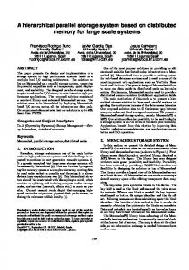
The CBE is an innovative chip multiprocessor which strives to achieve “supercomputer power” in an “everyday” processor. The CBE consists of a dual threaded general purpose control/OS processor built on the Power PC architecture.
353
Encoded Bitstream
Parser
Frame Buffer
Entropy Decoding
Inter/Intra Prediction
Deblocking Filter
Inverse Quantization/ Transform
Video Output
Figure 2: H.264 decoder computational complexity. The H.264 decoder’s complexity is about 2.5 times that of a comparable H.263 decoder [7]. The H.264 codec is commonly used for mass video storage applications such as Blu-ray Disc and broadcast/streaming video where minimizing bandwidth and storage space without loss of perceived video quality is extremely important. As HD video becomes more popular, this kind of improvement in storage efficiency is increasingly urgent. However, due to the increase in computational complexity associated with H.264, the cost of decoding 1920x1080 resolution HD streams cannot be ignored. Decoder implementations capable of handling real time HD decoding without dedicated hardware acceleration are exceedingly rare.
Figure 1: IBM Cell Architecture as presented by Pham et al. [15]. PPE: Power Processor Element, PPU/PXU: Power Processor Unit, EIB: Element Interconnect Bus, SPU/E: Synergistic Processor Unit/Element, LS: Local Store, SMF: Synergistic Memory Flow Control, LS: Local Store, SXU: SPU Core, MIC: Memory Interface Controller, BIC: Bus Interface Controller.
1.3
The Power Processing Unit (PPU) is connected to eight simpler Synergistic Processing Units (SPUs) via the Element Interconnect Bus (EIB). The SPUs have extensive support for Single Instruction Multiple Data (SIMD) operations up to single precision floating point, and are able to access main memory directly through a Memory Flow Controller (MFC) which manages Direct Memory Access (DMA) activity in the SPU. Each SPU includes a 128x128 bit register file and a scratchpad memory Local Store (LS) of 256KB which is shared between data and instructions, and must be carefully managed by the programmer [1]. The CBE has the potential to provide exceptional performance for complex data intensive operations such as H.264 video decoding given an effective parallelization scheme. In designing a parallelization scheme for the decoder on the CBE, we must consider limitations such as available bandwidth for communication between processing units, memory limitations for code, data, stack, and heap in the SPU, and the need for synchronization management in the PPU.
1.2
FFmpeg’s H.264 Decoder
FFmpeg is a popular open source audio and video conversion and streaming project capable of handling a wide range of video and audio codecs based on the libavcodec library [5]. Since FFmpeg supports a large number of codecs and encapsulation, the code base is large with over 250k lines of code. Our base code is the ffmpeg command line tool source code configured to include only the H.264 decoder and YUV encoder, and unused source files (associated with other codecs) are removed. The data structures and control flow built into the FFmpeg H.264 decoder center on decoding one Macroblock (MB) at a time. The decoder maintains a tree of elements and structures rooted in a data structure, H264Context, which holds the current state of the decoder, including modes and data associated with the current MB, arrays for accessing information about neighboring MBs, references to the current output picture and any reference pictures etc. This structure is passed from one function to the next conveying the state of the decoder and the MB under consideration. Figure 3 illustrates key control flow elements and functions of the main MB decoding loop within decode slice(). After returning from the entropy decoding, decode mb cabac(), H264Context is filled with all information and block data needed to decode the current MB. This data is passed to hl decode mb() where the MB is predicted, residual data is recovered via IDCT, and deblocking is performed on the resulting image data which is placed in the current picture result. An important program flow characteristic is that this process is repeated for each MB until the decoder reaches the end of the current slice when control exits the loop and writes the frame to the output if there are no more slices. This process is repeated for each slice in the video.
H.264
H.264/AVC is part of the MPEG-4 suite of multimedia standards. The first revision of the standard, completed in May 2003, sought to address increasing demand on video bandwidth associated with growing services like High Definition (HD) television and Internet based streaming video applications [20]. A high level diagram of the decoder is given in Figure 2. H.264 implements a number of improvements over previous video codecs which collectively result in reductions of up to 50% in bandwidth requirements for the same level of image quality. The savings result from extensive analysis and optimization in the encoder which serves to minimize redundancy in the video stream, but comes at a significant cost in
2.
PREVIOUS WORK
A lot of effort has gone toward parallelizing the H.264 codec. Detailed analysis of opportunities for parallelization in the encoder and decoder are available. Li and Chen present multithreading considerations of the H.264 decoder
354
B
B
B
B
PPU
while !slice_end { decode_slice() }
SPU GOP
... a.
hl_motion()
idct...()
GOP
Baik et al. in contrast with our implementation. In Baik’s implementation, parallelism is derived at the inter coded block level where intra block-dependencies need not be addressed. The design utilizes both data and functional partitioning by partitioning MBs from inter coded frames among the available SPUs in a load balanced fashion, and dedicating an additional SPU to deblocking. The PPU manages entropy decoding, intra decoding, and other overhead associated with decoding. We consider our implementation to have greater scalability since we address the data dependencies imposed by intra coded blocks whether the frame is an intra (I) or inter (P, B) coded frame. Our implementation also distributes the deblocking effort, and removes all decoding activities from the PPU except for entropy decoding which is inherently non-parallelizable.
filter_mb()
pred...() mc_part()
...
mc...() mc...() mc...() mc...()
b.
P
I
Figure 4: Frame types
for i < MBs_per_row{ hl_decode_mb(mb[i]) }
pred...() pred...() pred...()
P
I
for i < MBs_per_row { decode_mb_cabac(mb[i]) }
mc...() mc...() mc...()
Figure 3: FFmpeg main MB decoding loop, a. Intra decoding functions, b. Inter (motion compensation) decoding functions.
in the context of hyper-threading technology [10]. Rodriguez et al. look at GOP and slice level scalability in the encoder running on a cluster of processors [17]. In their paper, Tol et al. look at functional and data partitioning and present an argument for the use of data partitioning for scalability [18]. Cong et al. look at managing tracking data dependencies in the front end for parallelization addressing issues that make static scheduling difficult or impossible in video coders [6]. Hwang et al. look at parallelization of reference code applied to the H.264 encoder. [8]. Alverez et al. present a characterization of the H.264 decoder’s performance emphasizing HD, suggesting better media architecture support and multiprocessor support [3]. Zhuo and Liang present a wavefront parallelization data partitioning and task scheduling scheme for the H.264 encoder [22]. In their study on parallel scalability of video decoders, Meenderinck et al. [11] [12] study the amount of parallelism which can be extracted from the decoder and present a 3D wavefront scheme for extremely high scalability. They look at data structures and dependencies, and point out scalability problems with slice, frame, and intra coded MB levels of data parallelism. Alvarez discusses the scalability of MB-level parallelism for H.264 [2]. Seitner et al. give a simulation based comparison of several MB level parallelization approaches with resource-restricted environments in mind. Their “Single-row approach” is essentially the same scheme which we have implemented for the CBE. The advantages of this scheme are good scalability and reduced synchronization complexity. Seitner points out that the disadvantage of this scheme is the relatively high inter-processor data dependency which results in increased bandwidth requirements. Multicore encoder and decoder implementations are presented in [4] [9] [14] [21]. Two of the these H.264 implementations, Yuan [21] and Baik [4] implement H.264 decoders on the CBE. Yuan’s document describes a decoder demonstration, but there is no further information on the implementation. We will look at the design from Samsung’s
3. 3.1
PARALLELIZATION OPPORTUNITIES Frame Level
The video stream is composed of a series of video frames organized into many Groups of Pictures (GOPs) with a sequence of frames starting with an I frame followed by a sequence of P and B frames. The I frame is independently coded, but the P and B frames have data dependencies with other frames in the GOP. Figure 4 illustrates the dependency relationships between the GOP, I, P, and B frames. The GOP is not dependent on another GOP for decoding purposes which exposes a level of parallelism; however, GOP level parallelism imposes an enormous memory requirement for HD resolution and embedded applications in particular and can have undesirable latencies [11]. Frame level parallelism is also possible based on the dependencies between P and B frames, but this level of parallelism is generally not scalable beyond two or three simultaneous frames and still imposes significant memory requirements.
3.2
Slice Level
Within the image frame another straightforward scheme for parallelization presents itself at the slice-level. Slices are groups of independently encoded macroblocks within a frame which could be decoded independently in parallel. The current FFmpeg H.264 decoder already supports thread parallel decoding at this level. Unfortunately, H.264 encoded video frames are not generally encoded using a large number of slices which limits parallel scalability. Although increasing the number of slices in an encoded video frame can improve error correction performance when streaming over a lossy network, increasing the number of slices also reduces the compression efficiency of the encoder by eliminating many opportunities for exploiting redundancies in the data. For this reason H.264 encoded videos commonly use one slice per frame.
355
0
5 4
MA B C D E F GH I J 2 K L
SPU n
SPU 1 SPU 2
Figure 5: Intra coding modes and dependencies [16]. The nine 4x4 intra modes (0-8) are indicated with the direction of an arrow into the 4x4 pixel block in the figure. Mode 2 is the DC mode. The empty pixels in the 4x4 block are predicted using an algorithm to sweep the indexed pixels in the direction of the arrow.
Vertical
Figure 7: Each row of MBs in a video frame are assigned to one SPU in round-robin order. The MB data dependencies which must be met for the first three intra coded blocks in the second row are indicated with arrows. Both intra and inter blocks are subject to the vertical and horizontal dependencies indicated which apply to the deblocking filter as well as intra prediction.
SPU 1
SPU 2 SPU 3
Horizontal
SPU 1
A
B C
͙
͙
Figure 8: Synchronization between three SPUs. SPU 1 has completed the first row and started working on row 4. SPU2 is working on MB A which has satisfied dependencies. SPU3 is stalled on MB B awaiting completion of MB A.
Figure 6: Data dependencies of the 4x4 edge filtering algorithms are indicated by the diamond ended horizontal an vertical lines. The filter may use four pixels on either side of the top horizontal or the left vertical border of the 4x4 block and may modify three pixels on either side.
4. 3.3
͙
͙
8
SPU 2 ͙
1
3
͙
6
SPU 1
7
Macroblock Level
4.1
Another possibility for parallelization is at the MB level, inter coded blocks are always independent from other inter coded blocks in the same frame exposing a tremendous amount of data parallelism, possibly thousands of MBs per frame in HD video. When we consider intra coded MBs on the other hand, we must deal with inter-block dependencies within the frame. Now we have a requirement that some blocks must be decoded before others within the same frame. Figure 5 illustrates the possible prediction modes used to decode an intra coded MB. In case of mode 0 (Vertical), the bottom row of pixels from the MB in the previous row, directly above the current MB, is used to predict or partially reconstruct the current MB. Figure 6 illustrates the data dependencies associated with the 4x4 deblocking filter. The filter depends on almost the same neighboring blocks as intra prediction, only requiring more pixels from those blocks. It is clear from the figure that there are no intra dependencies on macroblocks in any other row while decoding the first row of a frame, but intra coded macroblocks in all other rows depend on macroblocks in previously decoded rows.
IMPLEMENTED SCHEME One Row Issue
Our H.264 parallelization scheme focuses on data parallelism at the Macroblock level. Dependencies between Intracoded MBs are addressed by partitioning a video frame into rows of MBs and assigning one full row of MBs to each decoding core as indicated in Figure 7. Our scheme assigns a row of macroblocks to a single SPU, the next row is assigned to the next SPU and so on in round-robin fashion. Figure 8 illustrates the inter SPU data dependencies due to intra coded MBs. A stall occurs when unfinished decoding of the reference MB from the previous row results in unresolved data dependencies. Note that the horizontal dependency only occurs within an SPU. Our data and functional partitioning schemes are illustrated in Figure 9, and Figure 3 highlights the dividing line between PPU and SPU in the control flow graph. Decoding overhead and entropy decoding tasks are executed in the PPU. One row of decompressed MBs is set aside for each SPU in raster scan order. The SPUs retrieve the data as required using DMA transfers and must handle synchronization required to meet intra dependencies. Since all MBs are issued in row order regardless of their prediction mode, we
356
PPU
SPU 1
SPU 2
«
SPU N
H_DYNAMIC[0] H_DYNAMIC[1] H_DYNAMIC[2] H_DYNAMIC[3]
Slice Start
H_DYNAMIC[W]
Entropy Decode One Row Notify SPU n Row Data Ready
Row Start
Row Start
H_STATIC
Row Start
no
Slice End?
DMA get DMA get
DMA get
DMA get
Decode MBxx44 Dec. MB
Dec. MB x 4
Dec. MB x 4
Filter MB MB xx44 Filter
Filter MB x 4
Filter MB x 4
DMA put DMA put
yes
no
Row End?
yes Slice Finish
Row Finish
DMA put
no
Row End?
yes Row Finish
H264Context
DMA put
no
Row End?
yes
Figure 10: Data structure modifications reducing memory requirements in the local store. W is the width of the video frame in macroblocks.
Row Finish
Figure 9: Scalable decoder partitioning scheme. Dotted lines represent communication signals. DMA transfers between SPUs and main memory are not indicated. The PPU loop generates one row at a time of entropy decoded MBs. A PPU-SPU signal assigns the row to an SPU and notifies the SPU that data is ready for decoding. The SPU loop completes decoding each MB in the row and returns the results to main memory. Except for synchronization signals, data is passed from SPU to SPU via the current picture store in main memory.
shallow, with a (somewhat simplified) depth of three as seen in the figure. We have experimentally determined that the stack may approach 100KB which must be reserved in the LS memory map to prevent a stack overflow. The width of the tree as indicated in Figure 3 suggests a large number of possible functions may be called. Our implementation includes just under 200 functions totaling approximately 160KB in total LS memory requirements. Additionally, while minimizing memory requirements where possible, our implementation requires at least 50KB in data memory, which with the 100KB requirement for stack/execution memory, means that 100KB of available memory in the 256KB LS must accommodate the 160KB of code. This 60KB memory shortage is overcome using a technique called code overlay which allows us to map multiple segments of code to a single address in the LS, and manage which code segments are available in the scratchpad memory. An overlay manager manages a table to track which functions are available and uploads called function code when it is found to be missing from the LS. The overlay manager implements a direct mapping scheme with a user defined mapping to write missing functions into the LS. The user provides a linker script which describes the overlay mapping. The overlay mapping is defined in terms of segments and regions. Each segment refers to a specific block of code, and a region refers to a specific location in the memory mapping. If we map two code segments to the same region, then they will share the same address in memory, and only one may be present in the LS at a time. The linker supports mapping one object file to each segment. Object files may be placed into their own segments or grouped together to form a larger segment. Since the resolution at which the linker handles code segments is the object file, we can control the configurability of our code with respect to the LS memory map by arranging source code into separate source files for each potential code segment. Practically, this means placing the source code for each function into a separate source file in order to achieve the greatest resolution. In this way, we have the freedom to implement an SPU mapping which addresses the sequence in which functions will be called and the possibility of additional overhead associated with each function call. In this section we will assume that each function is mapped to a segment, and each
can easily handle dependency synchronization requirements for intra coded MBs whenever they occur in a P or B frame in addition to I frames.
5. 5.1
IMPLEMENTATION Data Structures
A critical first step in executing any decoding software on the Cell SPUs is understanding and managing memory requirements. The SPU’s 256kB Local Store (LS) is relatively generous by current distributed memory chip multiprocessor standards, but it cannot hold the approximately 30k lines of code plus data we will need for MB decoding. Figure 10 illustrates our modification to the H264Context structure for use in the SPU. Only the subset of the decoding context represented by H STATIC and H DYNAMIC are present in the SPU. Instances of H DYNAMIC present represent a sliding window of MBs from the SPU’s assigned row.
5.2
Code Overlay
The 256KB SPU Local Store scratchpad memory is partitioned and shared among the program instructions, program data, the execution stack, and heap for any dynamically allocated structures. For our purposes, the stack size is constrained by the tree depth of the function call graph for the portion of H.264 decoder code to be executed on the SPU. The basic structure of this function call graph is seen in Figure 3. Stack memory requirements for this portion of the decoder are well bounded as there are no recursive function calls. Although the tree is wide, it is also relatively
357
10x 10x 5x
5x
21
10 x f21()
Figure 12: Example function call graph.
Region 2
remains prohibitive since we must consider the interactions of hundreds of functions to choose from an astronomically large set of feasible mappings, |N|. Considering the possible combinations of segments per region and functions per segment, even limiting the solution space to two regions we find that: !! n Y i |N| = Ω ⌊i/2⌋ i=1
Figure 11: Example code overlay mapping showing a 4K section of memory with addresses labeled across the bottom. Memory is divided into regions. Multiple segments may be mapped to the same region or address. Region sizes are determined by the largest segment they contain. Functions or object files are mapped to segments, and multiple objects may be mapped to the same segment.
This is a staggering number if we have on the order of n = 200 functions. To address this issue we look at heuristic steps taking into account key areas of interference between functions in the function call graph, and profiling information to help us understand which functions are called most frequently. The example function call graph in Figure 12 illustrates a key point about interference between functions and profiling data. The nodes in the graph are given in function call order from left to right with each function looping 5 or 10 times. The execution sequence on the right indicates how many times the given function has instructions issuing, and consequently must be present in the LS. Profiling data tells us that f21() is called 50 times, but we can see that the number of times its caller, f11(), appears in the execution trace is 80 due to its caller-callee relationship with f20() and f21(). f11() is exposed to at least 60% more interference than any other function even though the profiler tells us it has been called at least 50% less often than any other function. An example of this type of function is hl decode mb(), as indicated in Figure 3. This function calls a wide range of other functions, and contains several loops with function calls as in the example above. Key functions such as this one also tend to have elevated weights with respect to code overlay costs, as they tend to require more memory, contributing further to the cost of a miss by resulting in increased DMA delays any time they must be loaded into the LS. Step 1: The first step in our approach is to ensure that this type of interference is always addressed. Our starting point is a single region containing every function. This flat overlay mapping represents the worst case performance, but it also ensures that our code will fit into the SPU LS, as no further vertical compression is possible. We examine the function call graph to identify and prioritize key functions according to their overlay overhead cost. The cost is a function of the number of functions they are expected to call including any functions called from within loops, the priority of the called functions as discussed below, and the key function’s size. Functions with the correct structure, but which do not have interference relationships with important
segment has only one function mapped. Consequently, we use the term function interchangeably with segment. When an absent function is loaded into the LS, the interfering function which is present and mapped to same region is overwritten. The implication is that anytime a function is called and its code is missing from the LS, tasks which stall program execution must be executed resulting in additional function call overhead. This overhead comes from a small cost of the overlay manager’s table lookup, and the potentially significant cost of a DMA operation to bring the missing code into the LS. As we work to design an overlay mapping which not only enables us to squeeze the SPU executable into the LS, but also gives us the greatest benefit in terms of performance or throughput, it is this overhead which must be addressed.
5.2.1
5 x f11()
f1 f10 f1 f11 f20 f11 f21 f11 f1
20
func_3.0()
5 x f20()
0x1000
0x0800
func_3.1()
0x0C00
func_2.0()
Region 1 0x0400
Region 0
func_2.1()
10
1
func_1.0()
11
3
func_1.1() func_1.2()
0x0000
func_3.2() func_3.3()
22
10 x f10()
func_1.3()
2
func_1.4()
4
5
main()
time
func_1.5()
Designing an Overlay Mapping
In order to maximize performance with respect to code overlays, we need to minimize the number of overlay miss penalties incurred. Given a trace of the program execution and the overlay mapping, the number of miss penalties can be deterministically identified and an optimal mapping scheme is possible. This is true of many digital signal processing algorithms. Unfortunately, H.264 presents some problems which make finding a general optimal solution impossible. Uncertainty derives from the many possible modes and cases which must be handled such as the nine intra prediction possibilities for each 4x4 block of pixels, anywhere from one to 32 motion vectors for each inter-coded MB, a series of decisions and filters for each edge of each 4x4 block etc. The effect is that the decoder’s execution trace will vary dramatically from video to video, frame to frame, and MB to MB. In the presence of restricted memory resources, no one solution will give optimal results for every video. Even if we were able to use a decoding execution trace to find an optimal overlay mapping, solving for the optimal solution
358
Overlay Performance: Amazing Caves 50
35 30
35 30
Frame Rate (1/s fps)
Frame Rate (1/s fps)
Overlay Performance: Magic of Flight 50
25 20
15 2.5Mbps: Step 2 Overlay 2.5Mbps: Step 1 Overlay 2.5Mbps: Flat Overlay 10 0
50
25 20
15 2.5Mbps: Step 2 Overlay 2.5Mbps: Step 1 Overlay 2.5Mbps: Flat Overlay 10 0
100
Frame Number
50
100
Frame Number
(a) Magic of Flight
(b) Amazing Caves
Figure 13: Code overlay mapping performance for two videos. Each chart shows the worst case single region flat overlay, step one results after pulling key functions out of the flat region, and step two results after pulling priority profiling functions out. The horizontal bars indicate frame rates plotted on a time scale.
5.3
leaf functions may be given low priority and ignored. Key functions are removed from the original region and placed into a new region as long as memory is available. The SPU portion of the call graph in Figure 3 has two key functions, hl decode mb() and mc part(). Step 2: Next we can continue to improve overlay performance as long as we have memory available. Using profiling data from several videos, we can identify functions which are called frequently. The overlay mapping from the previous step overlays many functions, such as those associated with inter prediction in Figure 3, with each other in the same region. Since many of those functions are called with very high frequencies, they tend to interfere with one another. By profiling several videos, we can identify and prioritize the functions which tend to have very high call frequencies, and select those with the highest priority to be removed to a new region. Each move is guaranteed to improve performance as long as any other function in the losing region is called. We can continue to move high priority functions out of the shared memory location into new regions until there is no more room in memory. At this point we have prioritized and removed interference costs for the most expensive functions in the code. The metrics used to determine function priorities are empirically determined. Function size is a factor, but in reality we find that for the vast majority of functions, it contributes only to the consumption of available memory space, and not to performance of the overlay scheme. The reason for this is due to the intrinsic overhead of the DMA operation which we find results in identical DMA delays for functions close to 2KB in size and smaller. There are only a few exceptions in our codec where the DMA time is impacted by function size, and these tend to be key functions which were put into their own regions in the first step.
5.2.2
Synchronization
The dashed lines in Figure 9 represent the required synchronization signals. Although the SPU-SPU signals are implemented using a 128bit DMA, all PPU-SPU signals have been implemented using the blocking SPU in and out mailboxes. A PPU-SPU signal occurs when row data is ready and the row-designated SPU is notified that work can begin. SPUs notify the PPU of their busy state by passively placing a message in their outbox which the PPU checks before overwriting an SPU’s H DYNAMIC array. Image data is never transferred between SPUs. Instead, SPU n writes its results back to main memory before reporting any progress to SPU n+1 via DMA into the next SPU’s LS. Each SPU checks the progress of its predecessor before working on blocks with unresolved dependencies. Once the previous SPU reports sufficient progress, resolving any necessary dependencies, a DMA is initiated to acquire data for intra decoding and deblocking.
6.
IMPROVING PERFORMANCE
Performance improvements achieved using methods outlined in the following subsections are presented in Table 1. The improvements given are compared to the optimized code running on six SPUs without the individual optimization implemented.
6.1
Direct Memory Access (DMA)
DMA operations can be time consuming and are fundamental to multicore programming on the CBE. Poorly scheduled DMA operations can have dramatic adverse impact on performance. We were able to maximize video decoder throughput by minimizing the number of DMA operations, minimizing the size of DMA operations, and scheduling DMA barriers in order to minimize stalls due to outstanding memory accesses. Our parallelized decoder implementation requires four important memory operations: 1. Before beginning the row decoding process, SPUs must retrieve H STATIC data. 2. Before decoding a group of MBs, image data from the previous row for deblocking (which includes data needed for intra prediction) must be gathered. 3. During motion compensation, referenced image data must
Overlay Performance
Overlay mapping performance is presented in Figure 13. The effect of overlay mapping optimizations is consistent across different videos. It’s also clear from the figure that the speedup in terms of decoding time from optimizing out a few key functions in step 1 is similar to the step 2 speedup which applies to more than 100 additional functions.
359
Frame Decoding Time (s)
Video Amazing Caves Coral Reef Adv. Discoverers Robotica Speed Storm Chasers T2 Magic of Flight Rules of Attr. To the Limit
Decoder Components: Coral Reef Adv. 1SPU
0.35 0.30
Motion Vector DMAs
0.25 0.20
2.5Mbps: Full Decoder 2.5Mbps: No MV DMAs 2.5Mbps: No MV Decoding 2.5Mbps: No Deblocking 2.5Mbps: No MB Decoding
Motion Vector Decoding
0.15 Deblocking
0.10
Intra pred/IDCT/Dequant./Remaining DMAs
0.05 PPU: Entropy Decoding
0.00 0
50
100
Table 2: Benchmark Videos
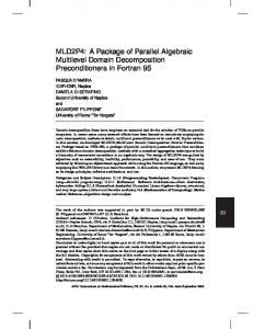
Frame Number Figure 14: Breakdown of decoder performance by component using a single SPU. Top line in the graph indicates the decoding time for each frame. The shaded areas represent the contribution of a portion of the decoder to the total time. Motion vector decoding and deblocking are the most expensive components. The white band at the bottom is the PPU (entropy decoder) contribution. Optimization DMA Scheduling Inlining SIMD Compiler IDCT unrolling
tion functions, IDCT, and deblocking have properties suitable for SIMDization. The PPC altivec functions available in the ffmpeg source provide this targeted improvement, but the Altivec functions must be transcoded to execute on the SPU, and have not been included in this work. We experimented extensively with IBM’s SIMDizing compiler, spuxlc, on applicable functions to achieve very limited SIMD improvement.
7.
Improvement 8.5% 7.2% 2.1% 0.3%
be retrieved for each motion vector. 4. Decoded image data must be returned to main memory. We push DMA completion barriers as far out as possible in order to hide the DMA operation with other work in the SPU. In this way we are able to significantly reduce or prevent stalls associated with DMA barriers.
Inlining
The process of dividing the ffmpeg source code into separate object files for each function has the side effect that compiler is no longer capable of inlining functions as specified in the original source code. Due to the importance of code overlay performance, we found that it is not always desirable to inline the same functions in the parallelized code as the original sequential code. Since inlining changes the size of the calling function by inserting the caller into its code, the DMA overheads and LS memory are both affected. We found experimentally that in most cases inlining did not improve performance, and could even reduce performance. However, a couple of very small functions, av clip() and copy block(), which are called with extremely high frequencies enabled substantial performance improvements when rewritten as macros to force inlining.
6.3
RESULTS
The benchmark videos used to test our decoder implementation were taken from Microsoft’s WMV HD demonstration page [13], and are listed in Table 2. The source videos were transcoded into H.264 1920x1080 (1080p) format at five different bitrates from 2.5Mbps to 16Mbps CAVLC and CABAC using the x264 H.264 encoder [19] integrated into ffmpeg. The videos were encoded using the x264 presets: baseline, normal, and hq. We additionally tested a modified version of the normal preset with B frame encoding removed, referred to in Figure 15(a) as modified-normal. Decoder performance is measured on the Sony’s Playstation 3, 3.2 GHz Cell Processor (limited by Sony for access to six of the CBE’s eight SPUs) running Fedora 9. We collected data for ten videos, four encoder preset configurations, and five bitrates, decoding on 1-6 SPUs. The performance data is presented in Figure 15. The charts show performance for one preset and either CAVLC or CABAC and each video by bitrate. Each bar indicates the performance in terms of decoding framerate for 1-6 SPUs with each SPU adding to the framerate. Figure 14 illustrates the contribution of various decoder components to the overall framerate. The largest contributors are MV decoding and deblocking, making them important for further optimization and SIMD vectorization. Results presented by Baik et al. for Samsung’s parallelized decoder [4] implemented on four SPUs show an average framerate of 20.5fps across four 1080p test videos CAVLC encoded with B frames at 2.5Mbps. Our implementation achieves an average 25.23fps or a 23% improvement when decoding similarly encoded video streams on four SPUs. We achieve substantial further improvements due to enhanced scalability using additional SPUs as seen in Figure 15(b). For videos encoded at the same bitrate, but using the higher quality and much more expensive CABAC encoder and x264 ’s hq encoding settings, our decoder still slightly outperforms the previous implementation even when limited to four cores. Our implementation achieved a “best case” average framerate of 34.94fps on 2.5Mbps modified-normal CAVLC encoded video streams on six SPUs, and a “worst case” entropy
Table 1: Optimization Improvements
6.2
Description cave scenery active underwater scenes night sky, lab workers fast panning and action sporting activities flight, storm clouds dark scene from T2, preview glider, fast panning post modern style cinemetography mountain climbing
Single Instruction Multiple Data
One of the major strengths of the CBE is its SIMD capabilities, available in both the PPU and SPU. The portion of code which we have implemented for the PPU is not well suited for SIMD instructions, but there are many opportunities for SIMD execution in the SPU code. Some intra predic-
360
Amazing Caves
Coral Reef Adv.
Discoverers
Robotica
Speed
Stormchasers
T2
Magic of Flight
Rules of Attr.
6SPU 5SPU 4SPU 3SPU 2SPU 1SPU
2.5M 4M 8M 12M 16M
2.5M 4M 8M 12M 16M
2.5M 4M 8M 12M 16M
2.5M 4M 8M 12M 16M
2.5M 4M 8M 12M 16M
2.5M 4M 8M 12M 16M
2.5M 4M 8M 12M 16M
2.5M 4M 8M 12M 16M
2.5M 4M 8M 12M 16M
H.264 Decoder Frame Rate Across Bitrates and Videos for 1-6 SPUs (x264: modified preset|CAVLC)
2.5M 4M 8M 12M 16M
Frame Rate (fps)
40 35 30 25 20 15 10 5 0
To The Limit
Amazing Caves
Coral Reef Adv.
Discoverers
Robotica
Speed
Stormchasers
T2
Magic of Flight
Rules of Attr.
6SPU 5SPU 4SPU 3SPU 2SPU 1SPU
2.5M 4M 8M 12M 16M
2.5M 4M 8M 12M 16M
2.5M 4M 8M 12M 16M
2.5M 4M 8M 12M 16M
2.5M 4M 8M 12M 16M
2.5M 4M 8M 12M 16M
2.5M 4M 8M 12M 16M
2.5M 4M 8M 12M 16M
H.264 Decoder Frame Rate Across Bitrates and Videos for 1-6 SPUs (x264: normal preset|CAVLC)
2.5M 4M 8M 12M 16M
40 35 30 25 20 15 10 5 0
2.5M 4M 8M 12M 16M
Frame Rate (fps)
(a) Modified Normal CAVLC
To The Limit
Amazing Caves
Coral Reef Adv.
Discoverers
Robotica
Speed
Stormchasers
T2
Magic of Flight
Rules of Attr.
6SPU 5SPU 4SPU 3SPU 2SPU 1SPU
2.5M 4M 8M 12M 16M
2.5M 4M 8M 12M 16M
2.5M 4M 8M 12M 16M
2.5M 4M 8M 12M 16M
2.5M 4M 8M 12M 16M
2.5M 4M 8M 12M 16M
2.5M 4M 8M 12M 16M
2.5M 4M 8M 12M 16M
H.264 Decoder Frame Rate Across Bitrates and Videos for 1-6 SPUs (x264: normal preset|CABAC)
2.5M 4M 8M 12M 16M
40 35 30 25 20 15 10 5 0
2.5M 4M 8M 12M 16M
Frame Rate (fps)
(b) Normal CAVLC
To The Limit
Amazing Caves
Coral Reef Adv.
Discoverers
Robotica
Speed
Stormchasers
(d) HQ CABAC
Figure 15: Results.
361
T2
Magic of Flight
Rules of Attr.
6SPU 5SPU 4SPU 3SPU 2SPU 1SPU
2.5M 4M 8M 12M 16M
2.5M 4M 8M 12M 16M
2.5M 4M 8M 12M 16M
2.5M 4M 8M 12M 16M
2.5M 4M 8M 12M 16M
2.5M 4M 8M 12M 16M
2.5M 4M 8M 12M 16M
2.5M 4M 8M 12M 16M
H.264 Decoder Frame Rate Across Bitrates and Videos for 1-6 SPUs (x264: hq preset|CABAC)
2.5M 4M 8M 12M 16M
40 35 30 25 20 15 10 5 0
2.5M 4M 8M 12M 16M
Frame Rate (fps)
(c) Normal CABAC
To The Limit
decoder limited average framerate of 15.43fps on 16Mbps hq CABAC encoded video streams. Decoder performance results suggest that additional cores will allow further performance improvement for most videos. In some cases, at higher bitrates the PPU entropy decoder becomes dominant, and no further gains are possible even with additional SPUs. This is evident in Figure 15(d), with the reduced or missing performance blocks for SPUs 5 and 6 at 8Mbps and higher. CABAC encoded videos are costlier to decode in the PPU, so maximum frame rates are more limited compared to CAVLC. When decoder performance is not completely limited by the entropy decoder, we see that the improvement gain from each additional SPU is slightly reduced from the previous SPU due to increased demand on the PPU and memory bandwidth requirements. However, the framerate improvement with the addition of SPU6 still averages 11.3% across all tested bitrates and 12.6% for bitrates below 12Mbps for CAVLC. The average improvement due to SPU6 for CABAC encoded videos is limited by the PPU/entropy decoder dominance beyond four SPUs at higher bitrates, but still averages 6.6% across all tested bitrates and 9.3% for bitrates below 12Mbps.
8.
[4] H. Baik, K.-H. Sihn, Y. il Kim, S. Bae, N. Han, and H. J. Song. Analysis and Parallelization of H.264 decoder on Cell Broadband Engine Architecture. In Signal Processing and Information Technology, pages 791–795. Samsung Electron. Co., Ltd., Suwon, Korea, 2007. [5] F. Bellard. FFmpeg. http://www.ffmpeg.org/. [6] J. Chong, N. Satish, B. Catanzaro, K. Ravindran, and K. Keutzer. Efficient Parallelization of H.264 Decoding With Macro Block Level Scheduling. In IEEE International Conference on Multimedia, pages 1874–1877. University of California, Berkeley, USA, 2007. [7] M. Horowitz, A. Joch, F. Kossentini, and A. Hallapuro. H.264/AVC Baseline Profile Decoder Complexity Analysis. IEEE Transactions on Circuits and Systems for Video Technology, 13(7):704–716, July 2003. [8] H. Hwang, T. Oh, and S. H. Hyunuk Jung. Conversion of Reference C Code to Dataflow Model: H.264 Encoder Case Study. In IEEE. Seoul National University KOREA, 2006. [9] I. Y. Lee, I.-H. Park, D.-W. Lee, and K.-Y. Choi. Implementation of the H.264/AVC Decoder Using the Nios II Processor. In Altera Nios˝ o II Embedded Processor Design Contest. Seoul National University, 2005. [10] E. Q. Li and Y.-K. Chen. Implementation of H.264 Encoder on General-Purpose Processors with Hyper-Threading Technology. In SPIE. Intel China Research Center, Beijing, 2004. [11] C. Meenderinck, A. Azevedo, M. Alvarez, B. Juurlink, , M. A. Mesa, and A. Ramirez. Parallel Scalability of Video Decoders. Delft University of Technology, 2008. [12] C. Meenderinck, A. Azevedo, M. Alvarez, B. Juurlink, , and A. Ramirez. Parallel Scalability of H.264. Delft University of Technology, 2008. [13] Microsoft Corporation. WMV HD Content Showcase. http://www.microsoft.com/windows/windowsmedia/ musicandvideo/hdvideo/contentshowcase.aspx. [14] J. Park and S. Ha. Performance Analysis of Parallel Execution of H.264 Encoder on the Cell Processor. In IEEE, ESTIMedia. Seoul National University, 2007. [15] D. Pham et al. Overview of the Architecture, Circuit Design, and Physical Implementation of a First-generation Cell Processor. In IEEE Journal of Solid-State Circuits, volume 41, pages 179–196. IBM, January 2006. [16] I. E. G. Richardson. H.264 and MPEG-4 Video Compression Video Coding for Next-generation Multimedia. Wiley, The Robert Gordon University, Aberdeen, UK, 2003. [17] A. Rodriguez, A. Gonzalez, and M. P. Malumbres. Hierarchical Parallelization of an H.264/AVC Video Encoder. In International Symposium on Parallel Computing in Electrical Engineering, pages 363–368. Technical University of Valencia, 2006. [18] E. B. van der Tol, E. G. Jaspers, and R. H. Gelderblom. Mapping of H.264 Decoding on a Multiprocessor Architecture. In Proceedings of the SPIE, Image and Video Communications and Processing, pages 1874–1877, 2003. [19] VideoLAN. x264 - a free h264/AVC encoder. http://www.videolan.org/developers/x264.html. [20] T. Wiegand, G. J. Sullivan, G. Bjntegaard, and A. Luthra. Overview of the H.264/AVC Video Coding Standard. IEEE Transactions on Circuits and Systems for Video Technology, 13(7):560–576, July 2003. [21] Y. Yuan, R. Yan, H. Li, X. Liu, and S. Xu. High Definition H.264 Decoding on Cell Broadband Engine. In Proceedings of the 15th international conference on Multimedia, pages 459–460. IBM China Research Lab, 2007. [22] Z. Zhao and P. Liang. Data Partition for Wavefront Parallelization of H.264 Video Encoder. In ISCAS. University of California, Riverside, 2006.
CONCLUSION
Parallelizing the FFmpeg H.264 decoder on the Cell Broadband Engine requires immense effort due to the codec’s notorious complexity, but there are substantial opportunities for parallelization and optimization. Primary implementation issues arise from SPU memory limitations and the large size and complexity of the source code and H.264 specification, synchronization requirements, and data dependencies. We have been able to demonstrate significant scalable performance gains from parallelization of the H.264 decoder and its implementation on the Cell Broadband Engine. We expect to see an increasing number of cores in embedded applications and processors like the CBE, only increasing the need for scalability as efforts continue to improve performance in the face of physical barriers for monolithic processors.
9.
ACKNOWLEDGMENTS
Michael A. Baker is sponsored by the U.S. Army’s Research Development and Engineering Command. The contents of this work reflect the views of the writers, who are responsible for the accuracy of the data presented herein. The contents do not necessarily reflect the official views or policies of the U.S. Army. This research has been supported in part by grant from SFAz and the Stardust Foundation. The authors would like to thank Aniruddha Kadne, and Nikhil Ghadge, ASU, for their investigations into FFmpeg optimizations, and David Offutt, ASU, for investigating SPUSPU communication.
10.
REFERENCES
[1] Cell Broadband Engine Architecture. IBM Systems and Technology Group, 2007. [2] M. Alvarez, A. Ramirez, X. Martorell, E. Ayguade, and M. Valero. Scalability of Macroblock-level Parallelism for H.264 Decoding. In ACACES. Technical University of Catalonia (UPC), 2008. [3] M. Alvarez, E. Salam´ı, A. Ramirez, and M. Valero. A Performance Characterization of High Definition Digital Video Decoding using H.264/AVC. In HiPEAC. Universitat Politecnica de Catalunya, 2005.
362