SCIENCE CHINA Technological Sciences • Article •
January 2015 Vol.58 No.1: 56–63 doi: 10.1007/s11431-014-5667-1
A simple compliance modeling method for flexure hinges ZHU ZhiWei, ZHOU XiaoQin*, WANG RongQi & LIU Qiang School of Mechanical Science and Engineering, Jilin University, Changchun 130022, China Received June 24, 2014; accepted September 1, 2014; published online October 24, 2014
Various types of flexure hinges have been introduced and implemented in a variety of fields due to their superior performances. The Castigliano’s second theorem, the Euler–Bernoulli beam theory based direct integration method and the unit-load method have been employed to analytically describe the elastic behavior of flexure hinges. However, all these methods require prior-knowledge of the beam theory and need to execute laborious integration operations for each term of the compliance matrix, thus highly decreasing the modeling efficiency and blocking practical applications of the modeling methods. In this paper, a novel finite beam based matrix modeling (FBMM) method is proposed to numerically obtain compliance matrices of flexure hinges with various shapes. The main concept of the method is to treat flexure hinges as serial connections of finite micro-beams, and the shearing and torsion effects of the hinges are especially considered to enhance the modeling accuracy. By means of matrix calculations, complete compliance matrices of flexure hinges can be derived effectively in one calculation process. A large number of numerical calculations are conducted for various types of flexure hinges with different shapes, and the results are compared with the ones obtained by conventional modeling methods. It demonstrates that the proposed modeling method is not only efficient but also accurate, and it is a more universal and more robust tool for describing elastic behavior of flexure hinges. flexure hinge, compliance matrix, finite beam based matrix modeling, modeling accuracy Citation:
Zhu Z W, Zhou X Q, Wang R Q, et al. A simple compliance modeling method for flexure hinges. Sci China Tech Sci, 2015, 58: 5663, doi: 10.1007/s11431-014-5667-1
1 Introduction Flexure hinges, serving as the substitutions of conventional joints, have been extensively employed in micro mechanical systems to obtain friction and lubrication free motions with high resolution, high precision and small structure sizes. Typical implementations can be found in micro-machining systems [1,2], micro/nano manipulators [3,4], and micro/nano positioning stages [5,6]. Up to date, various types of flexure hinges with different shapes and moving features have been introduced, such as right circular flexure hinges [7], leaf-spring flexure hinges [8,9], elliptical-arc-fillet flexure hinges [10,11], V-shaped flexure hinges [12,13],
conic flexure hinges [14–16], power function shaped flexure hinges [17], fillet flexure hinges [8,18,19], annulus-shaped flexure hinges [20,21], flexure hinges with freeform shapes [22,23] and so on. Developments of these types of flexure hinges will add more feasibility and flexibility to the design of flexural mechanisms, however, it will simultaneously rise difficulties for the design and optimization processes due to the complicated shapes of the flexure hinges which are usually hard to be accurately modeled [24,25]. Discussions of properties and analytical models of flexure hinges have been a long history [26–28]. To obtain accurate models of the elastic deformation behavior of the notched flexure hinges and accordingly have good estimations of moving features of the mechanisms, various efforts have been devoted by researchers to modeling the basic
*Corresponding author (email:
[email protected]) © Science China Press and Springer-Verlag Berlin Heidelberg 2014
tech.scichina.com link.springer.com
Zhu Z W, et al.
Sci China Tech Sci
compliances of the flexure hinges [7,11,27]. Currently, the Castigliano’s second theorem [8,13,15], the Euler–Bernoulli beam theory based direct integration method [10,14,18] and the unit-load method [17] are the three commonly used methods for analytically modeling the compliances of flexure hinges. Although closed-form compliance equations can be obtained through these methods, each term of the complete compliance matrix needs to be separately executed by laborious integral operations over the entire flexure length, significantly decreasing the modeling efficiency [29]. Besides, the modeling methods require prior-knowledge of the beam theory, blocking practical implementations in the industry. To avoid tedious mathematical descriptions of the compliance equations which are generally not concise enough for practical applications, high order polynomial approximation methods were employed to obtain empirical equations or dimensionless design graphs of certain sorts of flexure hinges [12,20,25]. Recently, great efforts have been focused on obtaining the generalized compliance models, and the generalized equations for the family of elliptical-arc-fillet flexure hinges and the family of conic-section flexure hinges have been introduced by means of unifying mathematical descriptions of the geometric shapes of the hinges [14,18,30,31]. However, as for certain flexure hinges with totally different dominant features, to obtain the unified mathematical descriptions seems to be difficult and even impossible. Thus, no universal compliance equations for flexure hinges with various shapes can be obtained, it is crucial to develop more universal and efficient modeling methods for flexure hinges, especially for the newly devel-
Figure 1
January (2015) Vol.58 No.1
57
oped ones. In this paper, a novel finite beam based matrix modeling (FBMM) method is proposed to numerically obtain compliance matrices of flexure hinges with complicated shapes. Comparing with conventional modeling methods, the main advantages of the FBMM can be summarized as follows: 1) It requires no knowledge of the beam theory and even the calculus, well extending practical applications of the FBMM; 2) terms of the complete compliance matrix can be obtained during one calculation process by simple matrix operation; 3) since matrix based calculation can be conducted more efficiently and accurately by computers [9, 32–34], the proposed modeling method will be very promising for facilitating computer-aided-design of flexure hinges; 4) in view of the modeling principle, compliance matrices of hinges with any shapes can be simply and directly obtained, even the ones described by discrete points.
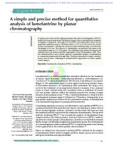
2 Compliance modeling Generally, in view of the shapes of the central axis, the flexure hinges can be categorized into two sorts, namely the circular- axis flexure hinges as shown in Figure 1(a) and the straight-axis flexure hinges. As for the straight-axis flexure hinges, they can be further categorized into two sorts from the view of notch shapes, namely the single-directional flexure hinge with variable width as shown in Figure 1(b), and the bi-directional flexure hinge with both variable width and variable thickness as shown in Figure 1(c). As shown in Figure 1, the o-xyz denotes the global Car-
Schematic of typical flexure hinges. (a) Circular-axis hinge; (b) single-directional hinge; (c) bi-directional hinge.
58
Zhu Z W, et al.
Sci China Tech Sci
tesian coordinate of the flexure hinges. As for the circular-axis flexure hinges shown in Figure 1(a), the shape of this sort of flexure hinges can be determined by the median radius R, the center angle m, and the radius of the two circle curves r1 and r2. y=f() denotes the mathematical description of the distance between the upper and the lower curves of the flexure hinges, respectively. For more details about the geometry and the mathematical descriptions, one can refer to ref. [35]. As for the straight-axis flexure hinges shown in Figures 1(b) and (c), l represents the total length of the notch; y=fw(x) and z=fb(x) denote the mathematical descriptions of the outer curves along the x-axis and the z-axis in the global coordinate frame, respectively. During the modeling, each sort of the flexure hinges will be uniformly divided into N pieces, and each piece can be treated as a micro Euler–Bernoulli beam with rectangular cross-section. The oixiyizi denotes the local Cartesian coordinate of the i-th micro- beam as shown in Figure 1. Overall, with the assumption that the effects of stress distribu-
Ci (L)
L Eb w i i 0 0 0 0 0
N
C Ti Ci (L)Ti T ,
where Ti denotes the compliance transformation matrix (CTM), Ci (L) denotes compliance matrix of the i-th single micro-beam in its local coordinate which has been proposed and widely employed for describing the elastic deformation behavior of the leaf-spring flexure hinges [9,36]. However, the complex shear effects are often ignored or simplified in these researches. Thus, to enhance the modeling accuracy, a modified version for the compliance matrix of the microbeam is derived by 0
0
L 4 L3 s 3 Ebi wi Gbi wi
0
0
0
0
L 4 L3 s Ebi3 wi Gbi wi
0
0
0
C x , M x
0
6 L2 Ebi3 wi
0
12 L Ebi3 wi
0
0
0
0
6 L2 Ebi wi3
12 11 . 10(1 )
(3)
zi 2 2.609 zi 1 7L 1 1 3 . 3 2G wi bi wi bi 1.17 zi 2 2.191zi 1.17
(4)
Referring to eq. (1), the CTM Ti takes on the following form [9, 32–34, 39]:
(1)
i 1
0
To accurately describe the torsion behavior of the microbeam, a newly developed torsion compliance which is thickness-to-width ratio independent is employed with the definition of the ratio zi=bi/wi [38]: C x , M x
tions on elastic deformations of flexure hinges can be ignored, each sort of the flexure hinges will be regarded as series connections of all the micro-beams. Based on the matrix based modeling method, the compliance of the flexure hinge in the global coordinate can be expressed by [1, 34]
0
where E and G are the modulus of elasticity and the modulus of rigidity, respectively. bi and wi denote the cross- section dimensions of the i-th micro-beam, L denotes the length of the micro-beam, and αs is the shear coefficient of the material. With being the Poisson ratio, the shear coefficient s introduced by Cowper for the micro-beams with rectangular cross-section is employed [37]:
s
January (2015) Vol.58 No.1
6 L2 Ebi wi3 0 , 0 0 12 L Ebi wi3 0
6 L2 Ebi3 wi
(2)
R ( ) Si ( ri ) Ri ( ) Ti = i , Ri ( ) O
(5)
where Ri(i) is the rotation matrix of the local coordinate oixiyizi with respect to the global coordinate o-xyz with a rotation angle i around the z-axis, which can be expressed by cos i Ri (i ) sin i 0
sin i cos i 0
0 0 , 1
(6)
ri is the position vector of the point oi expressed in the global coordinate. Si(ri) represents the skew-symmetric operator for the vector ri=[xi,yi,zi] with the notation: 0 Si zi yi
zi 0 xi
yi xi . 0
(7)
Zhu Z W, et al.
Sci China Tech Sci
As is discussed above, there are seven key parameters needed to be determined during the modeling process, namely the dimension parameters bi, wi, and L, the position vector ri=[xi, yi, zi] and the rotation angle i of the CTM. As for the straight-axis flexure hinges, the rotation angle i will be zero. The dimension parameters are bi=2fb(xi), wi=2fw(xi) and L=l/N. In view of the single- directional flexure hinges with just variable width, bi will be constant, i.e. bi=b0. The position vector will be ri=[xi, 0, 0]. In view of the circle-axis flexure hinges, bi is constant. wi can be derived in terms of the geometry model of the circular-axis flexure hinges presented in ref. [35]. Unlike the straight-axis flexure hinges, this sort of hinges will be uniformly divided in terms of the center angle m. The model parameters can be determined by i i , L R m / N , r [ R sin , R (1 cos ), 0]. i i i
(8)
For the number of the divided pieces N, it is definite that larger N will lead to more accurate results. Since the matrix computation process is computationally efficient, it will be a good solution to just choose a large enough value of N to obtain accurate enough results. In this paper, N is set as 1000.
3 Compliance modeling verification To verify the efficiency and the accuracy of the proposed method, the compliance matrices of two typical sorts of straight-axis flexure hinges including the elliptical-arc-fillet flexure hinges [10,18] and the power-function-shaped flexure hinges [13,17] are investigated, and the results are compared with the ones obtained by conventional methods. Besides, a newly reported two-segment circular-axis symmetric notch flexure hinge [35] and a family of bi-axis flexure hinges with both variable width and variable thickness [40–42] are also modeled and validated to demonstrate the feasibility of the proposed modeling method for flexure hinges with much more complicated shapes. 3.1 Compliance matrices of typical flexure hinges 3.1.1 Case 1: Elliptical-arc-fillet flexure hinges Chen et al. [10,18] proposed a sort of the generalized elliptical-arc-fillet flexure hinge which is illustrated in Figure 2, where a, b, t, l and m are dimensional parameters of the flexure hinge, governing the geometric feature. By choosing specified parameters, various types of flexure hinges, such as elliptical (E) types, elliptical arc (EA) types, elliptical fillet (EF) types, elliptical arc fillet (ECF) types, right circular (RC) types, circular (C) types, circular fillet (CF)
59
January (2015) Vol.58 No.1
types and so on, can be obtained. More details about this sort of flexure hinges and the geometric models can be found in refs. [10,18]. To investigate the accuracy of the proposed modeling method for this class of flexure hinges, the compliance matrices obtained by the FBMM are compared with the analytical results obtained in refs. [10,18]. During the calculation process, the modulus of elasticity and the modulus of rigidity are chosen as 2.07×10¹¹ and 8.1×10¹⁰ N/m2, respectively. The thickness is chosen to be 10 mm. The other dimensional parameters are detailed in Table 1. The first three types are from ref. [10], and the rests are from ref. [18]. Results obtained by Chen et al. [10,18] as well as the FBMM method are presented in Table 2 denoting as (C) and (Z), respectively. Since the global coordinates are not the same, only the absolute values are adopted to make comparisons. From the results shown in Table 2, except for x /Mx of the first three hinges, almost all the compliance results are equal, and only very slight deviations (