Automatica 40 (2004) 1239 – 1245 www.elsevier.com/locate/automatica
Brief paper
A singularity-free motion control algorithm for robot manipulators—a hybrid system approach! Jindong Tana;∗ , Ning Xib; c , Yuechao Wangc a Electrical
and Computer Engineering, Michigan Technological University, 121 EERC, 1400 Townsend Dr., Houghton, MI 49931, USA b Electrical and Computer Engineering, Michigan State University, East Lansing, MI 48824, USA c Shenyang Institute of Automation, Chinese Academy of Science, Shenyang, PR China Received 7 April 2003; received in revised form 1 October 2003; accepted 15 February 2004
Abstract This paper presents the design and implementation of a singularity-free tracking algorithm for robot manipulators using a hybrid system approach. A hybrid robot motion controller is designed to ensure feasible robot motion in the neighborhood of kinematic singularities. The hybrid control system has a two-layered hierarchical structure, a discrete layer and a continuous layer. The robot workspace is partitioned into subspaces based on the singular con!gurations of the robot. Switching between continuous controllers is involved when the robot travels across the subspaces. With the hybrid controller, the robot can work at the vicinity of singular con!gurations, but also can go through and stay at the singular con!gurations. The stability of the hybrid system is investigated using multiple Lyapunov function theory. Experimental results have demonstrated the advantages of the hybrid robot motion control method. ? 2004 Published by Elsevier Ltd. Keywords: Hybrid systems; Robotic manipulators; Switching control; Singularity; Tracking control
1. Introduction A robot task is usually described in its task space. The direct implementation of a task level controller can provide signi!cant application e"ciency and #exibility to a robotic operation. However, the major problem in the application of task level controller is the existence of kinematic singularities. While approaching a singular con!guration, the task level controller may generate high joint torques, which result in instability and large errors in the task space. The singularity-robust inverse (SRI) (Caccavale, Natale, Siciliano, & Villani, 1998; Cheng, Hour, Sun, & Chen, 1997; Chiaverini, 1997; Kir$canski, Kir$canshi, Lekovi$c, & Vukobratovi$c, 1997; Nakamura & Hanafusa, 1986) method was developed to provide an approximate solution to the inverse
!
This paper was not presented at any IFAC meeting. This paper was recommended for publication in revised form by Associate Editor Thor I. Fossen under the direction of Editor Hassan Khalil. Research partially supported under NSF Grant IIS-9796300, IIS-9796287 and EIA-9911077. ∗ Corresponding author. E-mail address:
[email protected] (J. Tan). 0005-1098/$ - see front matter ? 2004 Published by Elsevier Ltd. doi:10.1016/j.automatica.2004.02.013
kinematics problem around singular con!gurations. Instead of using exact motion control resulting in large torques, the SRI uses damped least squares (DLS) to provide approximate motion control close to the desired Cartesian trajectory. These methods reduce the torque applied to individual joints and achieve approximate motion. However, it can be shown (Kir$canski et al., 1997; O’Neil & Chen, 2000) that the system is unstable at the singular points, which means either the singular points cannot be actually reached or the robots cannot start from the singular points. Kir$canski et al. (1997) theoretically proved that at the singular points, the resolved acceleration control of robots has unstable saddles. The instability of this method for redundant mechanisms is discussed in O’Neil and Chen (2000). The aim of this paper is to develop a hybrid system approach for a task level robot tracking controller, which is stable in the entire robot workspace including the regions that contain singular con!gurations. The hybrid system approach is used to integrate di%erent continuous robot controllers, and singular conditions are adopted as switching conditions in discrete control. The stability of the hybrid system design is analyzed using the multiple Lyapunov function method.
1240
J. Tan et al. / Automatica 40 (2004) 1239 – 1245
2. Robot controllers and singularities 2.1. Robot controllers The dynamic model for a robot arm with n joints ˙ + g(q) = u, where can be written as D(q)q& + c(q; q) q = {q1 ; q2 ; : : : ; qn }T is the n × 1 vector of joint displacements, u is the n × 1 vector of applied torques, D(q) is the ˙ n × n positive de!nite manipulator inertia matrix, c(q; q) is the n × 1 centripetal and coriolis terms, and g(q) is the n × 1 vector of gravity term. A robot task can be de!ned in either joint space or task space. Robot controllers can be designed accordingly. In joint space, a robot task is speci!ed in an n-dimensional joint space denoted by qd ; q˙d ; q&d . A computed torque controller at joint level can be formulated as uj = D(q)(q&d + KVq eq2 + KPq eq1 ) + c + g;
(2.1)
where KVq and KPq are feedback gain matrices, eq = ˙ T . The error dynamics in joint [eq1 ; eq2 ]T = [qd − q; q˙d − q] space can be described by e˙q1 = eq2 ;
e˙q2 = −KPq eq1 − KVq eq2 :
(2.2)
It is straightforward to prove that system (2.2) is local asymptotically stable for appropriate gain matrices KPq ; KVq . Irrespective of the current robot con!guration, system (2.2) can track any reasonable trajectories given as qd ; q˙d ; q&d . In other words, controller (2.1) is valid in the entire workspace. However, a robot task is generally represented by the desired end-e%ector position and orientation. A robot controller in task space is therefore desirable. To develop a task level controller, the robot model needs to be represented in terms of task level variables. Therefore, the acceleration in task & The robot dyand joint space can be related as x& = J˙q˙ + J q. namic model in terms of extended task space variables can ˙ + c(q; q) ˙ + g(q) = u, then be described as DJ −1 (x& − J˙q) where the Jacobian matrix is n × n. Given the desired path in task space, xd , the robot controller in task space can be described as ut = DJ −1 (x&d − J˙q˙ + KVx ex2 + KPx ex1 ) + c + g;
(2.3)
e˙x2 = −KPx ex1 − KVx ex2 :
(2.4)
T
˙ The error dynamics where ex = [ex1 ; ex2 ] = [xd − x; x˙d − x]. in task space can be described as e˙x1 = ex2 ;
It is also easy to show that system (2.4) is local asymptotically stable for appropriate gain matrices KPx ; KVx . 2.2. Singularity analysis By comparing the controllers uj and ut in (2.1) and in (2.3), it can be seen that the existence of controller (2.3) depends on the existence of J −1 , while (2.1) does not. At a robot singular con!guration or in its vicinity, the Jacobian J is singular or ill-conditioned. The determinant of J −1 could
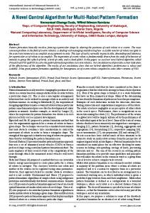
be very large, which will result in unreasonable large joint torques. The robot con!gurations are such that |J | = 0 are called robot singular con!gurations. Though an e%ect orientation de!nition, such as the quaternion representation, can avoid algorithmatic singularities, there are inescapable singular con!gurations for robot manipulators. The general way to evaluate the proximity to a singular con!guration is the singular value decomposition (SVD) of Jacobian matrix. The !nSVD of a Jacobian matrix J is de!ned as J = U!V T = i=1 "i ui viT , where U is the (n × n) orthonormal matrix of the output singular vectors ui , V is the (n × n) orthonormal matrix of the input singular vectors vi , and ! is a diagonal matrix whose elements are the singular values of J , "1 ; "2 ; : : : ; "n . When one or more of the singular values are close to zeroes, the robot is close to a singular con!guration. Given a mechanical structure, analytical expressions can be obtained to check the proximity to a singular con!guration. Generally, the singular con!gurations can be categorized for a given mechanical structure. A variable can be obtained to represent the proximity to a certain singular con!guration. For example, there are three categories of singular con!gurations for a PUMA-like robot arm: boundary singular con!guration, interior singular con!guration and wrist singular con!guration (Cheng et al. 1997). Therefore, a vector of three variables can be obtained to represent the proximity to each singular con!guration: # = [$b ; $i ; $w ]T = [d4 c3 − a3 s3 ; d4 s23 + a2 c2 + a3 c23 ; −s5 ]T , where si and ci stand for sin qi and cos qi , respectively. a2 ; a3 and d4 are robot parameters. By checking the value of the variables $ ∈ #, one can decide the proximity to the robot singular con!gurations. It is worth noting that it may be di"cult to !nd an analytical form of # for a general manipulator. 2.3. Workspace partitions The robot workspace, denoted by %, can be divided into three kinds of subspaces, denoted by %0 ; %1 ; %2 , respectively. In %0 , task level controller ut can be used. In %1 , a modi!ed task level controller based on SRI method (Caccavale et al., 1998; Chiaverini, 1997; Kir$canski et al., 1997) can be used to achieve approximate motion. %2 speci!es a smaller vicinity of the singular con!guration, where the modi!ed task level controller is unstable (Kir$canski et al., 1997). The workspace is partitioned based on the values of vector #. The de!nition of %1 and %2 are given as follows: %2 = {q ∈ Rn | $$(q)$ ¡ &; $(q) ∈ #}, %1 = {q ∈ Rn | & 6 $$$ 6 '; q %∈ %2 ; $ ∈ #}, where ' ¿ & ¿ 0. Fig. 1 shows an illustrative plot of the subspaces. It should be noticed that %0 ∪%1 ∪%2 =% and %0 ∩%1 ∩%2 =∅. The ( region, which is also called dwell region, is de!ned to avoid the chattering when switching occurs. The de!nition of a dwell region is given as: ( = {q ∈ Rn | & ¡ $$$ ¡ & + ); q %∈ %2 ; $ ∈ #}, where ) is a constant greater than zero.
J. Tan et al. / Automatica 40 (2004) 1239 – 1245
Fig. 1. Illustrative plot of the workspace partition.
3. Hybrid robot motion controller Hybrid control systems involve both continuous and discrete dynamic systems. The evolution of such systems is given by equations of motion that generally depend on both continuous and discrete variables. Fig. 2 shows a general framework for the hybrid system controllers. The hybrid controller has a two-layered hierarchical structure, which includes a continuous layer and a discrete layer. A discrete switching function is designed to determine the continuous controller to be used. The switching function is dependent on the proximity to the singular con!gurations and the previous controller status. When the robot approaches the singular con!gurations, the hybrid controller !rst uses damped least squares to achieve an approximate motion of the end e%ector. It will then switch into joint level control if the robot reaches the singular con!guration. The general design procedure is discussed as follows. The !rst step in the hybrid motion controller design is the singularity analysis of the manipulator and the partition of the workspace. For a given mechanical structures, the singular con!gurations and the corresponding singular condition vector # can be obtained. For examples, a vector of variables, #, is discussed in Section 2 to check the proximity to singular con!gurations. The second step is the design of the switching functions based on the de!nition of the subspaces. Two switching function vectors are generally necessary. One is the switching conditions between the regular region %0 and region %1 , the other is the switching function between region %1 and region %2 . The switching functions can be formulated as: ms1 =sgn(' −|$|)⊕0; ∀$ ∈ #, ms2 =ms2 (t − )sgn(&+)−|$|)⊕0 ⊕ sgn(& − |$|) ⊕ 0; ∀$ ∈ #, where sgn(·) is a signum
Robot
Task Level Control + + _
Task Level Control with DLS
Gravity, Coriolis and Centrifugal terms
Joint Level Control Singular Conditions
Fig. 2. Framework for hybrid system controllers.
1241
function. The switching function is a function of the singular conditions represented by Max-Plus Algebra. The Max-Plus algebra, widely used in the Discrete event systems, is de!ned as m(t) ∈ Rnmax , where Rmax = R ∪ {−∞}; ⊕ denotes the Max operation and ⊗ denotes the Plus operation. Here the operations ⊕ and ⊗ are de!ned as: a ⊕ b = max{a; b}, and a ⊗ b = a + b (Baccelli, Cohen, Olsder, & Quadrat, 1992). The expression ab in Max-Plus algebra corresponds to a · b in classical algebra. It can be seen that ms1 = 0 in %0 , ms1 = 1 in %1 and ms2 = 1 in %2 . It is worth noting that ms2 is not only a function of the singular condition vector #, but also a function of the current status of ms2 (t − ). It means that the switching condition for switching into a subspace and switching out a subspace may have different values. This is designed for eliminating the chattering characteristic of a switching controller. The third step is the design of the continuous controllers. Three continuous controllers are to be designed. In subspace %0 , the inverse of J always exists and the task level control (2.3) is e%ective in this subspace. In subspace %2 , the joint level controller is used. In region %1 , though it is close to a singular con!guration, a feasible solution of inverse Jacobian can be obtained by pseudo-inverse or singular robust inverse (SRI). Controller (2.3) can still be used after substituting J # for J −1 , where J # is a kind of pseudo-inverse represented by: J # = (J T · J + *ms1 · I )−1 J T , where * is the damping factor, and I is an identity matrix. Instead of using a constant damping factor, * is generally de!ned as a function of the singular value " (Chiaverini, 1997): * = *(") = −(*max ="min )" + *max . It is generally hard to compute the singular value online, the singular condition $ ∈ # is used in this design: * = *($) = −(*max =$min ) $ + *max , where the parameters *max and $min are chosen experimentally. The controller in region %1 can then be represented by ud = DJ # (x&d − J˙q˙ + KVx ex2 + KPx ex1 ) + c + g:
(3.1)
The error dynamics of the system can be described by e˙x1 = ex2 ; ˙ − K(KPx ex1 + KVx ex2 ): e˙x2 = (I − K)(x&d − J˙q)
(3.2)
Here K = JJ # . The stability analysis of controller (3.1) is discussed in Caccavale et al. (1998). However, it can be proved that the controller based on pseudo-inverse method will cause instability in subspace %2 (Kir$canski et al., 1997; O’Neil & Chen, 2000). Though subspace %2 could be very small, it cuts the dexterous workspace into pieces. If the robot cannot travel through subspace %2 , the singular con!gurations will greatly restrict the dexterous workspace. Thus, joint level control is enabled in subspace %2 to stabilize the system. With the continuous controllers in di%erent subspaces and the switch functions, the next step is to formulate the hybrid
1242
J. Tan et al. / Automatica 40 (2004) 1239 – 1245
robot motion controller in the entire workspace utilizing the switching conditions ms1 and ms2 : u = (1 − ms2 )ud + ms2 uj ;
(3.3)
where the switch function ms1 is within Eq. (3.1). The values of ms1 and ms2 determine the continuous controllers that should be used. ms2 takes the values of 1 or 0 and therefore ud is the controller for subspace %0 ∪ %1 , and uj is the controller for subspace %0 ∪ (. ms1 also takes the values of 1 or 0. When ms1 = 0, ud = ut and therefore Eqs. (3.1) and (2.3) are the same. When ms1 = 1, the damped least-square method is instantiated, and the inverse Jacobin is J # . The design of ms1 and ms2 is therefore the discrete controller design as discussed in the second step. Based on the stability analysis of the continuous controllers in their respective region, the stability of the hybrid motion controller in the entire workspace should also be investigated. The last step of the hybrid robot motion controller design is the path planning of the continuous controllers. Given the desired path in the task space, xd , controllers (2.3) and (3.1) can be implemented. However, when the controller switches to ud from uj , the task representation qd should be transformed to xd by the forward kinematics equation xd = h(qd ). When the controller switches to uj from ud , the task representation xd is transformed to qd , which involves the inverse kinematics at singular con!guration. At the vicinity of singular con!guration, substantial research has been done to solve the inverse kinematic problem. A damping least-square method can be used (Cheng et al., 1997; Nakamura & Hanafusa, 1986). By the relation between task space and joint space variables, x = h(q), a !rst-order approximation of the kinematic function at a con!guration q can be written as: dx = J (q) dq, where dx = xd − x and dq = qd − q represent motion increment in task space and joint space, respectively. At robot singular con!gurations, rank(J (q)) ¡ n. Given a reasonable dx, it may result in a very large joint motions dq if the assigned dx has components along the degenerated directions. To balance the accuracy and feasibility of the joint space motion, the following criterion is used to !nd the inverse kinematics: minqd {w1 $dx − J (q) dq)$2 + w2 $qd − q$2 }, where w1 and w2 are positive weight factors. This criterion minimizes the deviation after the task is mapped onto joint space, and tries to !nd qd such that the least joint movement is needed. An optimal solution to this can be written as: dq = w1 (w1 J T (q)J (q) + w2 )−1 J (q)T dx (Nakamura & Hanafusa, 1986). At the neighborhood of singular con!gurations, an appropriate increment or decrement dx could result in a large increment or decrement dq. dq needs to be reparameterized in joint space to satisfy the velocity and acceleration constraints. The continuity of joint velocities and task level velocities are also considered in the planning. After switching from task level control to joint level, the initial velocity for every joint is the joint velocity prior to switching.
4. Stability analysis This section discusses the stability of controller (3.3) when switching between the controllers in (3.1) and (2.1) is involved. Theorem. Assume joint level controller (2:1) is asymptotically stable in workspace and task level controller (3:1) is uniformly ultimate bounded in region %1 , there exists a constant ) ¿ 0, as shown in Fig. 1 and the de!nition of (, is such that the hybrid robot motion controller (3:3) is ultimate-bounded in the entire workspace of the robot. Proof. The error dynamics of the manipulator in joint space and task space can be represented by Eqs. (2.2) and (3.2), respectively. It is easy to prove that system (2.2) is stable. Eq. (3.2) has been proved to be ultimately bounded in %0 ∪ %1 . However, if the controller switches between uj (2.1) and ut (3.1), the system will switch between (2.2) and (3.2). Since the state variables in dynamics models (2.2) and (3.2) are di%erent, the relation between the state variables in model (2.2), (3.2) is derived !rst. It is easy to prove that x = h(q) and x˙ = J q˙ are Lipschitz continuous in their de!ned domain, i.e., $ex1 $ = $xd − x$
= $h(qd ) − h(q)$ 6 L1 $qd − q$ = L1 $eq1 $;
˙ ˙ = $J (qd )q˙d − J (q)q$ $ex2 $ = $x˙d − x$
˙ 6 $J (qd )q˙d − J (q)q˙d $ + $J (q)q˙d − J (q)q$
˙ 6 c1 · $qd − q$ ·$ qd $ + c2 · $q˙d − q$ = L2 $eq1 $ + L3 $eq2 $;
where L1 , L2 and L3 are constants that depends on the upper bound on $J (q)$ and $qd $. Here it is reasonable to assume that the maximum joint velocity and the Jacobian are bounded. The boundedness of Jacobin applies only to revolute joints. In summary, the following relation between joint space error and task space error can be found # " L1 0 $ex $ 6 $eq $ = Lb $eq $; L2 L3 where Lb is a constant. Similar to the above inequality, the following relation can also be obtained based on the Lipschitz continuity of the function q = h−1 (x); q˙ = J −1 x˙ in %0 ∪ %1 : $eq $ 6 La $ex $. Therefore, the errors in joint space and task space satisfy the following inequality in %0 ∪ %1 : $eq $ 6 La $ex $, $ex $ 6 Lb $eq $. De!ning the Lyapunov function of system (2.2), (3.2) T T V1 = 12 (eq1 KPq eq1 + eq2 eq2 ); T V2 = 12 [ex1 Kex1 + (+ex1 + ex2 )T (+ex1 + ex2 )]:
J. Tan et al. / Automatica 40 (2004) 1239 – 1245
1243
e(1−+)(−*1 (t2 −t1 )−*2 (t1 −t0 )) V2 (ex (t0 ))
V
6 e(1−+)(−*1 (t2 −t1 )−*2 (t1 −t0 )) V2 (ex (t0 ));
V2
for c e+(−*1 (t2 −t1 )−*2 (t1 −t0 )) 6 1:
V2
V1
V2
V1
t0
t1
t2
t3
V1 t4
t5
t6
t
Fig. 3. A typical switching sequence of the hybrid control.
Since system (2.2) has been proved asymptotically stable in the entire workspace, and (3.2) has been proved to be uniformly ultimate bounded, the Lyapunov functions satisfy the inequalities in region %0 ∪%1 (Chapter 3 in Khalil, 1996) a1 $eq $2 6 V1 6 b1 $eq $2 ;
@V1 (eq ) fq (eq ) 6 − c1 $eq $2 ; @eq
a2 $ex $2 6 V2 6 b2 $ex $2 ;
@V2 (ex ) fx (ex ) 6 − c2 $ex $2 ; @ex
where a1 ; b1 ; c1 ; a2 ; b2 ; c2 are positive scalars. For an initial time t0 , the following inequalities can be obtained: V1 (eq (t0 + ,1 )) 6 e−*1 ,1 V1 (eq (t0 ));
(4.1)
V2 (ex (t0 + ,2 )) 6 e−*2 ,2 V2 (ex (t0 ));
(4.2)
where *1 = c1 =b1 and *2 = c2 =b2 are positive scalars. Note that Eq. (4.2) is valid for $ex $ ¿ -. Here - is the ultimate bound for the controller ud in subspace %1 . It is shown that the gain matrices KPx and KVx can be used to reduce the value of - (Caccavale et al., 1998). In order to prove the stability of the hybrid controller (3.3), it is essential to show that V1 is monotonically decreasing at all odd number of switch instances, t1 ; t3 ; t5 ; : : : ; and V2 is monotonically decreasing at all even switching instances, t0 ; t2 ; t4 ; : : : . Based on the switching sequence in Fig. 3, V1 (eq (t1 )) 6 b1 $eq (t1 )$2 6 b1 La $ex (t1 )$2 6
b1 L a b1 La −*2 (t1 −t0 ) V2 (ex (t1 )) 6 e V2 (ex (t0 )); a2 a2
V2 (ex (t2 )) 6 b2 $ex (t2 )$2 6 b2 Lb $eq (t2 )$2 6
b2 L b b2 Lb −*1 (t2 −t1 ) V1 (eq (t2 )) 6 e V1 (eq (t1 )) a1 a1
6
b2 Lb b1 La −*1 (t2 −t1 ) −*2 (t1 −t0 ) e e V2 (ex (t0 )): a1 a2
From the above inequalities, it can be seen that b2 Lb b1 La −*1 (t2 −t1 ) −*2 (t1 −t0 ) V2 (ex (t2 )) 6 e e V2 (ex (t0 )) a1 a2 = c e+(−*1 (t2 −t1 )−*2 (t1 −t0 )) ∗
Here c = (b2 Lb =a1 )(b1 La =a2 ) is a constant and 0 ¡ + ¡ 1. Based on multiple Lyapunov function method (Branicky, 1998; Peleties & Decarlo, 1991), the system can be proved to be stable as long as (4.3) holds. It means that ce+(−*1 (t2 −t1 )−*2 (t1 −t0 )) 6 1 is a su"cient condition for the stability of the system during switching. This can be achieved by regulating two sets of parameters, *1 and *2 ; t2 − t1 and t1 − t0 . The values of *1 and *2 are related to the gain matrices Kpx ; Kvx ; Kpq and Kvq . In the implementation of the controller, high gains and high sampling frequency are chosen to ensure proper *1 and *2 . The values of t2 − t1 and t1 − t0 are also related to ). The boundary for switching into and out of a continuous controller is not the same. This forms the dwell region (, and can e%ectively avoid chattering at switching. From the de!nition of (, the value of ms2 cannot be changed immediately. Since t2 − t1 and t1 − t0 are time intervals when a continuous controller is enabled, they can be regulated by the value of ). Therefore, the gain matrices and the size of the dwell region ( are used to ensure that ce+(−*1 (t2 −t1 )−*2 (t1 −t0 )) 6 1. In the proof, the maximum velocity and acceleration vM and aM are assumed to be bounded. The dwell region ( corresponds to dwell time, such as t2 − t1 and t1 − t0 . The above analysis is valid for $ex $ ¿ - and the switching system is uniformly ultimate bounded. In the design of the controllers, the size of the dwell region can be chosen based on two situations. The !rst one is the ultimate bound. Considering controller (3.1) is ultimate-bounded by -, therefore $ex $ ¿ $ex1 $ ¿ -1 should be ensured by ). The other one is the gain matrix and motion planning. It can be proved that the transition of ex and eq are bounded by their initial values during switching. The bound is related to the gain matrices and the desired trajectory. It can be assumed that the initial value of errors is also bounded. Therefore, ex and eq are bounded. Thus, ) can be chosen that eq (t) ∈ %2 for t ¿ T and T is a time instance after !nite switches between joint level and task level control. By choosing an appropriate region, the switching sequence can also be completed in one cycle. The same procedure can be applied to time instances t4 ; t6 ; : : : ; for V2 . Therefore, V2 is monotonically decreasing at all even switching instances. Similarly, V1 is monotonically decreasing at all odd switching instances t1 ; t3 ; t5 ; : : : . Thus, the switching system is stable. 5. Experimental results The proposed hybrid robot motion controller was implemented on a PUMA 560 robot. The parameters are chosen as 'i = 'w = 0:15, 'b = 0:25, ) = 0:04, &i = 0:08,
1244
J. Tan et al. / Automatica 40 (2004) 1239 – 1245 x position
1
y position 0.16
x position
0.2
5
x 10-3
y position
0.1 0.14 y (m)
x (m)
0.9 0.8
0 -0.1
0.12
0.7
0
-0.2 -0.3
0.1
-0.4 0.6
0
2
(a)
4
6
t(sec)
0.08
(b)
rb
z (m)
-0.29 -0.3
6
2
4 t(sec)
10
20
30
0
0.53
0.2
0.525
0
0.52
-0.2
0.515
-0.4
6
0
(d)
2
4
6
t(sec)
Fig. 4. At boundary singular con!guration, dashed line: desired; solid line: actual.
&b = 0:08, &w = 0:03, ki0 = kw0 = 0:2, kb0 = 1, w1 = w2 = 1, KPx = diag(4800; 6000; 4800; 200; 200; 280), KVx = diag(80:0; 88:1; 88:2; 22:0; 24:0; 25:6), KPq =diag(2400; 2400; 2400; 1100; 1100; 1100), KVq = diag(50:2; 50:5; 50:1; 36:0; 36:0; 36:0). All the parameters are determined experimentally. The sampling period is set as 1 ms. Given a path, the trajectory was computed based on the path planning approach in Fu, Gonzalez, and Lee (1987). A trajectory is then formed by integrating temporal parameters with the given geometrical path considering the velocity and acceleration constraints. In the !gures, the unit for position is meters. For angles, it is radians. Fig. 4 shows experimental results of the hybrid motion controller when the robot approached its arm singular con!gurations at x = 0:9; y = 0:15; z = −0:297. The task of the robot was to move along x direction from 0.7 to 0:9 m. It can be seen that the tracking errors in y and z directions were much smaller and the task was completed. It is worth noting that the path was replanned in joint space after the controller switch into joint level control. The trajectory was planned in joint space such that the joint motion constraints were satis!ed. The end e%ector is slowed down to avoid unreasonable joint velocities. Fig. 4(d) shows the proximity to the singular con!gurations. Fig. 5 shows the position tracking result when both interior and wrist singularities were reached in the motion. At time t = 8 s, both interior and wrist singular con!gurations were reached, the controller switches into joint level. Errors caused by switching at t = 12 s can be seen from Figs. 5(a)–(c). The fourth !gure shows the proximity to the singular con!gurations. This also shows that the hybrid system was stable when double singular con!gurations were reached.
0.51
0
10
(c)
20 t
20
30
t
singular conditions, doted:ri; solid:rw
z position
-0.2 -0.3
10
(b)
t
0.535
-0.6 0
-5 0
-0.1
-0.5
-0.32
-0.5
(a)
-0.4
-0.31
(c)
4
measurement of rb
0
-0.28
2 t(sec)
z position
-0.27
0
0.4
30
-0.6 0
(d)
10
20
30
t
Fig. 5. With both interior and wrist singular con!gurations, dashed line: desired; solid line: actual.
6. Conclusions This paper presents a hybrid system design of task level robot motion controller that can work at and near singular con!gurations. Furthermore, the stability of the hybrid controller has been theoretically proved using multiple Lyapunov functions method. With the hybrid task level robot motion controller, the robot can work stably in the entire reachable workspace. The hybrid controller not only enlarges the workspace at task level, but also ensures the safety of the operations. The new hybrid task level robot motion control can be easily implemented based on the existing joint level controller and task level controller.
References Baccelli, F. L., Cohen, G., Olsder, G. J., & Quadrat, J. (1992). Synchronization and linearity, an algebra for discrete event systems. New York: Wiley. Branicky, M. S. (1998). Multiple lyapunov functions and other analysis tools for switched and hybrid systems. IEEE Transactions on Automatic Control, 43(4), 475–482. Caccavale, F., Natale, C., Siciliano, B., & Villani, L. (1998). Resolved-acceleration control of robot manipulators: A critical review with experiments. ROBOTICA, 16(5), 565–573. Cheng, F. T., Hour, T. L., Sun, Y. Y., & Chen, T. H. (1997). Study and resolution of singularities for a 6 dof puma manipulators. IEEE Transactions on Systems, Man and Cybernetics B: Cybernetics, 27(2), 332–343. Chiaverini, S. (1997). Singularity-robust task-priority redundancy resolution for real-time kinematic control of robot manipulators. IEEE Transactions on Robotics and Automation, 13(3), 398–410. Fu, K. S., Gonzalez, R. C., & Lee, C. S. G. (1987). Robotics: control, sensing vision, and intelligence. New York: McGraw-Hill.
J. Tan et al. / Automatica 40 (2004) 1239 – 1245
1245
Khalil, H. K. (1996). Nonlinear systems. Englewood Cli%s, NJ: Prentice Hall, Inc. Kir$canski, M., Kir$canshi, N., Lekovi$c, D., & Vukobratovi$c, M. (1997). An experimental study of resolved acceleration control of robots at singularities: Damped least-squares approach. Transactions of the ASME: Journal of Dynamic Systems, Measurement and Control, 119, 97–101. Nakamura, Y., & Hanafusa, H. (1986). Inverse kinematic solutions with singularity robustness for robot manipulator control. Transactions of the ASME: Journal of Dynamic Systems, Measurement and Control, 108, 163–171. O’Neil, K., & Chen, Y.-C. (2000). Instability of pseudoinverse acceleration control of redundant mechanisms. In Proceedings of IEEE ICRA, San Francisco, CA (pp. 2575–2582). Peleties, P., & Decarlo, R. (1991). Asymptotic stability of m-switched systems using lyapunov-like functions. In Proceedings of American control conference (pp. 1679–1683).
Ning Xi received his D.Sc. degree in Systems Science and Mathematics from Washington University in St. Louis, Missouri in December, 1993. He received his M.S. degree in computer science from Northeastern University, Boston, Massachusetts, and B.S. degree in Electrical Engineering from Beijing University of Aeronautics and Astronautics. Currently, he is an associate professor in the Department of Electrical and Computer Engineering at Michigan State University. Xi received the Best Paper Award in IEEE/RSJ International Conference on Intelligent Robots and Systems in August, 1995. He also received the Best Paper Award in the 1998 Japan-USA Symposium on Flexible Automation. Xi was awarded the !rst Early Academic Career Award by the IEEE Robotics and Automation Society in May, 1999. In addition, he is also a recipient of National Science Foundation CAREER Award. Currently, his research interests include robotics, manufacturing automation, micro/nano systems, and intelligent control and systems.
Jindong Tan received his Ph.D. degree in Electrical and Computer Engineering from Michigan State University, East Lansing, MI, 2002. He is currently an Assistant Professor in Department of Electrical and Computer Engineering, Michigan Technological University. His research interests include cooperation of distributed robots, mobile wireless sensor networks, human machine interaction, networked control systems and mobile computing. Dr. Tan is a member of the IEEE, ACM and Sigma Xi.
Yuechao Wang received his master degree in Pattern Recognition and Intelligent Control from Shenyang Institute of Automation, Chinese Academy of Sciences in 1987. He received his Ph.D. degree in Mechatronic Engineering from Harbin Institute of Technology in 1999. Since 1987, he has been with the Shenyang Institute of Automation, Chinese Academy of Sciences (SIA, CAS). He is currently a professor and the director of the SIA, CAS. His current research interests include robot control, multirobot systems, and Micro-nano manipulations.