SOFTWARE PROCESS IMPROVEMENT AND PRACTICE Softw. Process Improve. Pract. 2006; 11: 521–538 Published online 27 July 2006 in Wiley InterScience (www.interscience.wiley.com) DOI: 10.1002/spip.294
A Situational Implementation Method for Web-based Content Management System-applications: Method Engineering and Validation in Practice
Research Section
Inge van de Weerd,1 *† Sjaak Brinkkemper,1 Jurriaan Souer2 and Johan Versendaal1 1
Department of Information and Computing Sciences, Utrecht University, PO Box 80.089, 3508TB Utrecht, The Netherlands 2 GX, Wijchenseweg 111, 6538 SW, Nijmegen, The Netherlands
The usage of data-intensive web applications raises problems concerning consistency, navigation, and data duplication. Content management systems (CMSs) can overcome these problems. In this research, we focus on special types of web content management systems – webbased CMS applications. Currently, no general available methods exist for implementing and configuring these applications. In this research, an assembly based situational method engineering approach is proposed for constructing an implementation method for web-based CMS applications. The approach consists of four steps: (a) identification of implementation situations, (b) selection of candidate methods, (c) analysis and storage of relevant fragments in the method base, and (d) assembly of the new method using route maps to obtain situationality. This method engineering approach is supported by a meta-modeling technique, resulting in a process-data diagram, which integrates UML (Unified Modeling Language) activity diagrams and class diagrams. To validate the method, two case studies were performed at a large health insurance organization and a telecommunication organization in the Netherlands. The new implementation method performed well in both case studies, and the project workers were satisfied with the associated templates and instructions. Copyright 2006 John Wiley & Sons, Ltd. KEY WORDS: web-based CMS applications; content management system; situational method engineering; implementation method; meta-modeling; web-application
∗ Correspondence to: Inge van de Weerd, Department of Information and Computing Sciences, Utrecht University, PO Box 80.089, 3508TB Utrecht, The Netherlands † E-mail:
[email protected]
Copyright 2006 John Wiley & Sons, Ltd.
Research Section
1. AN IMPLEMENTATION METHOD FOR WEB-BASED CMS APPLICATIONS A large number of information system development methods are available. Next to established methods like entity-relationship modeling (Chen 1976) and the more recent unified process (Jacobson et al. 1999), several methods and techniques for developing web applications have been developed. Examples are WebML (Ceri et al. 2000), UML-based web engineering (UWE) (Koch 2001), and W2000 (Baresi et al. 2001). These methods are significantly influenced from information system development methods. This is not surprising since web applications are a subtype of information systems (Souer et al. 2005). Gnaho (2001) acknowledges this in his definition of web applications: a web application is an information system providing facilities to access complex data and interactive services via the web, which changes the state of business. Using data-intensive web applications raised new problems concerning consistency, navigation, data duplication, content audit and control, tracking of content and mapping the website workflows on the business processes (Vidgen et al. 2001). The solution to these problems was found in content management (Robertson 2003, Vidgen et al. 2001). A content management system (CMS) makes it possible to create, archive, search, control, and publish information from within a flexible and integrated environment (Burzagli et al. 2004). Web-based CMS applications are special types of CMSs, which are defined as web applications for the management and control of information (Souer et al. 2005). Examples are GX WebManager (van Berkum et al. 2004), FatWire Content Server, and Tridion Web Content Management Edition. In this article, we concentrate on improving the process of implementing web-based CMS applications. The starting point of such an implementation project is a customer request for a running website fully integrated with back-office systems and third-party services. This is then realized partly by means of the standard web-based CMS application, configured specifically to the customer’s situation, and for the remainder by developing customized extensions. To our knowledge, in academic and professional literature no specific methods on this subject exist, although existing CMS vendors do have their own proprietary way of guiding CMSpackage implementation. Therefore, in this work Copyright 2006 John Wiley & Sons, Ltd.
522
I. van de Weerd et al.
we propose a new implementation method for webbased CMS applications.
1.1. Web-application Development Methods Implementing a web-based CMS application is different from developing a website or information system. In the latter case, you start usually from scratch or from an existing legacy system. However, with the implementation of a web-based CMS application, there already is a preconfigured product. There appear to be no methods available in the open literature. Some CMS vendors have defined their own methods, like Tridion and Fatwire, but these are not freely available. Therefore, we turn to existing methods in the field of information systems and web-application development methods. The first method we describe is the Unified Software Development Process (Unified Process), which is ‘a generic process framework that can be specialized for a very large class of software systems, for different application areas, different types of organizations, different competence levels, and different project sizes’ (Jacobson et al. 1999). The Unified Process is actually an information systems development method, and not a web-application design method. Nevertheless, we mention it because firstly in the commercial context, the Rational Unified Process, has emerged as a de facto standard software development process (Larman et al. 2001) and secondly, it has had a significant influence on later developed web-application design methods. Distinguishing features are captured in the following key words: use-case driven, architecture centric, iterative and incremental. The lifecycle consists of 4 phases, namely, inception, elaboration, construction and transition. In the four phases, five core workflows are addressed: requirements, analysis, design, implantation and test. Since 1998, several methods and techniques for specifically designing web applications have been developed. First, in 1998 the Website Design Method (WSDM) was developed by De Troyer and Leune. WSDM is a user-centered method for the design of kiosk websites. A kiosk website mainly provides information and allows users to navigate through that information (De Troyer and Leune 1998). The two basic characteristics of WSDM are the audience driven approach, and the explicit conceptual design phase. Softw. Process Improve. Pract., 2006; 11: 521–538 DOI: 10.1002/spip
Research Section
Subsequently, Sauer and Engels (1999) proposed the UML Extension for Modeling Multimedia Applications. They define a multimedia application as an application that combines at least two media objects and shows time-dynamic behavior. Aspects of the application that are covered in this extension are: (a) logical structure; (b) spatial presentation; (c) predefined temporal behavior; and (d) interactive control. Another extension was developed by Baumeister et al. (1999). They proposed this UML Extension for Hypermedia Design, because the diagrams of UML are not sufficient to model aspects such as navigational space and graphical representation. Koch (2001) proposed the UWE approach. This approach is object-oriented, visualized with UML and based on the Unified Process. UWE is a systematic, prescriptive, user-centric, UML-based, iterative and incremental method for adaptive hypermedia systems (Koch 2001). Brusilovsky, as cited in Koch (2001), provides the following definition of adaptive hypermedia systems: ‘hypermedia systems which reflect some features of the user in a user model and use this model by adapting various visible aspects of the system to the user’. UWE covers the full development process, divided into requirements analysis, conceptual, navigation and presentation design (Koch 2001). WebML is a notation for specifying complex websites at the conceptual level (Ceri et al. 2000). Its specification consists of four perspectives: (a) the structural model; (b) the hypertext model; (c) the presentation model; and (d) the personal model. It is not based on UML, but it is compliant with it. It does not propose a new language for data modeling, but is compatible with existing notations such as E-R modeling and UML. Also, WebML supports XML syntax, which can be fed to software generators for automatically producing the implementation of a website (Ceri et al. 2000). Finally, W2000 is a framework for designing web applications based on the preexisting assets UML and HDM (Baresi et al. 2001). According to the authors, the integration between UML and HDM consists in (a) defining several stereotypes and customizations of diagrams to render HDM with UML; (b) specifying guidelines to use UML as a way to specify some of the dynamic and operational aspects of web applications; and (c) refining use-case diagrams to describe high-level user requirements, Copyright 2006 John Wiley & Sons, Ltd. DOI: 10.1002/spip
Method Engineering and Validation in Practice
related to both functional and navigational aspects (Baresi et al. 2001).
1.2. Research Question and Design Over the years, web applications have evolved and make use of web-based CMS applications. Since the existing web-application development methods do not cover the issues that arise when implementing a web-based CMS application, there is a need for methods for implementing web-based CMS applications. This led us to our central research question: ‘How should a general applicable design method be constructed for the process of implementing web-based CMS-applications?’ This research project is carried out following the design research methodology for performing research in information systems as described by March and Smith (1995) and Vaishnavi and Kuechler (2004). Design research involves the analysis of the use and performance of designed artifacts to understand, explain and, very frequently, to improve on the behavior of aspects of Information Systems (Vaishnavi and Kuechler 2004). The design cycle consists of 5 process steps: (a) awareness of the problem, (b) suggestion, (c) development, (d) evaluation, and (e) conclusion. The design cycle is an iterative process; knowledge produced in the process by constructing and evaluating new artifacts is used as an input for a better awareness of the problem. Following the cycle defined in the design research methodology, we start with the awareness of the problem. This step has been described in the beginning of Section 1. The second step is the suggestion of a solution to the problem. This step comprises the suggestion of an assembly based situational method engineering approach, which is described in Section 2. In Sections 3 and 4, the next step in the design cycle is covered, i.e. the development of the new design method. Then, in Section 5 the method is evaluated in a case study. The results of this case study lead to a higher level of problem awareness, or suggestions for solutions. In the final section, conclusions and areas for further research are covered. Requirements analysis is an important part of software projects. Among others, Lowe and Henderson-Sellers (2001), highlight the need for a design-driven requirements process that structures the way in which design activities for web Softw. Process Improve. Pract., 2006; 11: 521–538
523
Research Section
systems can be linked to the clarification of requirements through an appropriate model of domain uncertainty. Escalona and Koch (2004) state that ‘web-applications require a more extensive and detailed requirements engineering process due to the number of stakeholders involved and due to the diversity of the requirements’. Therefore, the focus of this article, and consequently the deliverable (the design method), is on the Definition phase, which comprises requirements identification, description and validation.
2. ASSEMBLY BASED SITUATIONAL METHOD ENGINEERING We use assembly based situational method engineering to develop the new design method. The advantage of such a method is that we can reuse relevant, established method fragments of existing methods. In this way, an optimized method for every implementation situation is being developed. A modeling technique that integrates activity and class diagrams is developed for the purpose of analyzing existing methods and assembling new methods. In this section, we will elaborate further on the method engineering approach and the metamodeling technique. 2.1. Method Engineering Approach Kumar and Welke (1992) state that ‘there is no detailed information systems methodology which is the best in all situations’. They introduced a solution to this problem, method(ology) engineering, which describes the engineering of information system development methods by taking into account the uniqueness of a project situation. In addition, Brinkkemper (1996) defined method engineering as ‘the engineering discipline to design, construct and adapt methods, techniques and tools for the development of information systems’. van Slooten and Brinkkemper (1993) introduced route maps, where method fragments are combined to form new methods. Route maps can be used to tune the method into situational methods (van Slooten and Hodes 1996, Aydin and Harmsen 2002). Rossi et al. (2000) mention the development of UML extensions as a reaction to the abundance of variants of UML for special purposes as a prime example of successful situational method engineering. Also, Dietzsch (2002) showed that situational Copyright 2006 John Wiley & Sons, Ltd.
524
I. van de Weerd et al.
method engineering can be used as an appropriate approach for solving the problem to finding the right method. Recent research in the method engineering area has been done by Ralyt´e et al. (2003). They developed a generic process model for situational method engineering. This process model contains three approaches: the assembly based strategy, the extension-based strategy, and the paradigm-based strategy (Ralyt´e et al. 2003). ˚ Karlsson and Agerfalk (2004) use method configuration to adapt a particular method to various situated factors. The difference with assembly based method engineering is that the focus is on one method that is configured in a particular situation, instead of using a set of methods as a base for assembly. The approach to situational method engineering described in most literature is quite clear. Brinkkemper (1996) recognized the following steps: (a) characterization of the project, (b) selection of method fragments (that are stored in a method base), and (c) assembly of method fragments. The experience gained in this process is a new input for the method base. Saeki (2003) states that the simplest way to construct a new method is first to put meaningful method fragments in a method base, then to select useful method fragments from this method base, and finally to adapt and integrate them in a new method. Ralyt´e et al. (2003) have developed the assembly based process model for situational method engineering. This model describes three steps to develop a new situational method. The steps are: (a) specify method requirements, (b) select method fragments and (c) assemble method fragments. In the described research, it is either assumed that the method base with method fragments is already filled, or that the methods that are to be stored in the method base are already selected. In case of developing methods for a relatively new information systems field, the method base needs to be filled first. Therefore, for our new design method, we propose the following steps in an assembly based method engineering approach: 1. Analyze implementation situations and identify needs. 2. Select candidate methods that meet one or more aspects of the identified needs. Softw. Process Improve. Pract., 2006; 11: 521–538 DOI: 10.1002/spip
Research Section
3. 4.
Analyze candidate methods and store relevant method fragments in a method base. Select useful method fragments and assemble them in a new method by using use route map configuration to obtain situational methods.
We use this method engineering approach to develop a new method for implementing webbased CMS applications. Note however, that this is a generic approach and also usable in other fields. 2.2. Meta-modeling Technique Our method engineering approach is supported by a meta-modeling technique that is especially developed for method engineering purposes in order to model the activities and artifacts of the new development method. This technique, in which a
Method Engineering and Validation in Practice
so-called process-data diagram is built, is used in analyzing, storing, selecting, and assembling the method fragments. Saeki (2003) proposed the use of a meta-modeling technique for the purpose of attaching semantic information to the artifacts and for measuring their quality using this information. In this research, the meta-modeling technique is adopted and adjusted to reveal the relations between activities (the process) and data (the deliverables produced in the process) of the development method. This makes it possible to fragmentize methods and to configure both the process and data perspective of a situational method. The process-data diagram we use consists of two integrated meta-models. On the left-hand side is a meta-process model based on a UML activity
Figure 1. Process-data diagram Copyright 2006 John Wiley & Sons, Ltd. DOI: 10.1002/spip
Softw. Process Improve. Pract., 2006; 11: 521–538
525
Research Section
diagram (OMG 2003), and on the right-hand side is a meta-data model that is based on a UML class diagram (OMG 2003). In Figure 1, the integration of both meta-models, which results in a processdata diagram, is shown in a generic fashion. The dotted arrows indicate which concepts are created or adjusted in the corresponding activities. Actual examples of process-data diagrams that play a role in this research are shown in Figures 3, 4, 5, and 7. Some unique adjustments to the standard UML notation in both the activity diagram side and class diagram side have been made. The first adjustments are unordered activities. Unordered activities are used when subactivities within an activity do not have a predefined sequence in which they need to be carried out. This construction is very useful, as many methodical activities do not have sequential preferences. An example is describing the product vision, which consists of the subactivities describing the background, goals, assumptions, features and scope. No predefined sequence needs to be followed through these subactivities. In Figure 1, Activity 2 is illustrated as containing three subactivities. Subactivity 4 is sequential and Subactivity 5 and Subactivity 6 are unordered. Note that the fragmentation of the method is performed according to the decomposition of activities. Another adjustment is the use of three different types of concepts. We need these different types to indicate whether a concept is simple or compound. The difference between both concepts is that a simple concept does not contain any subconcepts and a compound concept is an aggregate of subconcepts. For the purpose of abbreviation, it is sometimes better to not depict the subconcepts of a compound concept. Altogether, we use three different types of concepts: • Simple concept, which contains no further (sub) concepts. A simple concept is visualized with a rectangle. An example of a simple concept is visualized in Figure 2, namely, the concept ACTOR. Although this concept contains no further (sub) concepts, it can possess attributes. Another example of a simple concept is a term in a glossary. • Open concept, which is an expanded compound concept that consists of a collection of (sub) concepts. An open concept is visualized with an open shadow. In Figure 2, USE CASE MODEL Copyright 2006 John Wiley & Sons, Ltd.
526
I. van de Weerd et al.
Figure 2. Example of simple, open and closed concepts
is represented as an open concept, as it consists of one or more ACTORS and one or more USE CASES. Another example of an open concept is a class diagram (OMG 2003), consisting of several classes and relations. • Closed concept, which is an unexpanded compound concept that consists of a collection of (sub) concepts. A closed concept is visualized with a closed shadow. USE CASE in Figure 2 is an example of a closed concept. Note that the context of which it is modeled is important. A USE CASE is detailed in a USE CASE DESCRIPTION, in which the flow of events, conditions, special requirements, priority etc. are described. Also, a USE CASE can have a PRIORITY. Because in this model we decided it is unnecessary to reveal that information, the USE CASE is illustrated with a closed concept. Another example of a closed concept is a class diagram.
3. ENGINEERING THE NEW IMPLEMENTATION METHOD 3.1. Context The research described in this work was carried out at GX creative online development, a web technology company in the Netherlands. GX is active in the fields of content management, online application development and integration of backend systems in portal solutions. The company implements web applications, using GX WebManager, a generic in-house developed webbased CMS application. GX WebManager enables people without a specific technological background in creating, maintaining and integrating several dynamic websites and portals. In addition to their product, the company also provides a service, which is creating a web-application ‘around’ the web-based CMS application. Examples of web applications built using WebManager are: www.ajax.nl, www.unicef.nl Softw. Process Improve. Pract., 2006; 11: 521–538 DOI: 10.1002/spip
Research Section
and the sites of the postal code lotteries: www.postcodeloterij.nl, www.postcodelottery.co. uk, www.postkodlotteriet.se. The development of these web applications was carried out by a proprietary method. However, the need existed to optimize this method in order to save time and money. Also, the need for a standardized webapplication development method existed, which could be used by implementation partners of the company. In the next subsections, the development of the new method is outlined, following the four steps as described in Section 2.1. 3.2. Implementation Situation Analysis Brinkkemper (1996), as well as Kumar and Welke (1992), stress the importance of distinguishing development situations. In this research, we use the term implementation situations, since the project deals with the implementation of a web-based CMS application. Consequently, the first step in the method engineering process is to analyze the projects, categorize them in implementation situations, and identify their specific requirements. The categorization of implementation situations is based on their distinguishing characteristics. Karlsson (2002) followed a similar process as Brinkkemper (1996) and Kumar and Welke (1992) in abstracting projects into development situations, but for the purpose of method configuration. He defined a characteristic of a development situation as: ‘a delimited part of a development situation, focusing on a certain problem or aspect which the method configuration aims to solve or handle’. We adopt this definition to define a characteristic of an implementation situation: ‘a characteristic is a delimited part of an implementation situation, focusing on a certain problem or aspect which the method aims to solve or handle’. Product software implementation projects are relatively small compared to projects in other information system areas (e.g. developing tailor-made software). In 2004, GX completed about 80 implementation projects, which vary in size, sector and type. About 80% of the implementation projects were done in less then 400 man-hours. Also, the project teams were relatively small, usually ranging from 3 to 8 members. The number of employees of the customer organizations ranges from a few to tens of thousands of employees. Usually the customer organization also has a project team of a few Copyright 2006 John Wiley & Sons, Ltd. DOI: 10.1002/spip
Method Engineering and Validation in Practice
persons. Their task is to provide the GX project team with information, monitor the process, and when the web application is being delivered, fill it with content. The implementations have been executed in a range of industries, like services, sports organizations, publishing companies, media, government, education, and health care. Resulting from artifact research and semistructured interviews, we concluded that three main types of implementation situations exist at GX: standard, complex and migration projects. The latter is easy to identify. When a large amount of content from an existing WebManager application needs to be migrated to the new WebManager version, this is classified as a migration project. However, the difference between standard and complex implementation situations is more ambiguous. Kumar and Welke (1992) and van Slooten and Hodes (1996) mention several characteristics for the categorization of development projects that are of importance. In general, one can state that these factors are deduced from the context, organization or from technical aspects from the project (Karlsson 2002). In Table 1, the adopted characteristics per area are described. The characteristics listed in Table 1 can be used to categorize the development situations. Every characteristic can be labeled with a value: high or low. In general, we state that the complexity of an implementation situation depends on the amount of characteristics that is labeled with a high value. When more than three of the values are high, it should be categorized as a complex development situation. Otherwise, it is a standard development situation. In this work, we focus on standard and complex development situations. Requirements were obtained by conducting semistructured interviews Table 1. Implementation situation characteristics Area
Characteristic
Context
Dependency to external activities and conditions Level of innovation of the applied technology, methods, tools and techniques Number of stakeholders Uncertainty of customer’s expectations by management team Uncertainty of development activities by customer Complexity of functional components Number of relationships to existing systems
Organization
Technique
Softw. Process Improve. Pract., 2006; 11: 521–538
527
Research Section
I. van de Weerd et al.
with consultants, project managers, and software architects; and artifact analysis of existing requirements specifications and project evaluation documents. Several problems were found and translated into overall needs, standard implementation situation needs, and complex implementation situation needs. In Table 2, an excerpt is given of a total of 12 needs that were identified for the implementation situations. For reasons of space, only a few examples are given. The complete overview is described by van de Weerd (2005). 3.3. Candidate Method Selection The following step is the selection of candidate methods from which method fragments are extracted and stored in a method base. After conducting literature research, we chose to make use of Unified Process (Jacobson et al. 1999) and UWE (Koch 2001). In choosing these candidate methods, the following considerations were taken into account: (a) the Unified Process is very suitable to divide into fragments and store in a method base; (b) UWE combines the strengths of the Unified Process with several web-specific characteristics; (c) consultants who are going to use the method are already familiar with RUP, the commercial variant of the Unified Process; and (d) both methods use UML as the modeling language, which is the standard notation for modeling object-oriented systems and widely accepted by the software engineering community (Baresi et al. 2001). 3.4. Candidate Method Analysis All three methods, GX development process, Unified Process and UWE, are analyzed by creating
meta-models in a process-data diagram. From every method, main and subactivities are identified. Each of these activities results in a deliverable, which is represented at the data-side of the diagram. Figure 3 illustrates a simple method fragment that is a part of the requirements workflow in UWE. On the process-side, one activity (Use case modeling) and four subactivities are shown. The first subactivity, Find actors and use cases, results in the concepts ACTOR and USE CASE. Next, a PRIORITY is given; the USE CASE is then detailed by providing it with a DESCRIPTION; and, finally, the USE CASES are structured, which results in the USE CASE MODEL. The USE CASE DESCRIPTION is not expanded in this fragment, since the subconcepts (involved actors, conditions, sequence of events, etc.) of this compound concept were of no importance in this context. All diagrams that are produced form the method base, from which fragments are selected to assemble the new method. The complete method base can be found in van de Weerd (2005). 3.5. New Method Assembly On the basis of the defined implementation situations and requirements, we chose the method fragments to use in the new design method. In order to assemble the right method fragments to the implementation situations, the needs of every situation were examined, after which the method fragments were mapped with the implementation situations. We chose to represent the results of the method engineering process as a route map. The advantage of using route maps, compared to using different methods per situation, is that it preserves the method from inconsistencies and that
Table 2. Implementation situation needs (excerpt) Situation
Need
Standard & Complex
The method should deliver a Requirements Document that is understandable to the customer and informative for the stakeholders at GX. Standard project often have a small budget. This implies that the amount of time for specifying the requirements is limited. Therefore, the method should make it possible to translate the requirements quickly into WebManager solutions. A solution has to be found to the problem of changing requirements after the contract is signed. Although one can expect the requirements to change during the requirements analysis, the customer often does not understand that this affects the budget.
Standard
Complex
Copyright 2006 John Wiley & Sons, Ltd.
528
Softw. Process Improve. Pract., 2006; 11: 521–538 DOI: 10.1002/spip
Research Section
Method Engineering and Validation in Practice
Figure 3. Method fragment of the UWE requirements workflow
updating of the method is easier. The route map is static, that is, when an implementation situation is chosen, the route that is followed is definite. However, if usage of the method indicates that parts of the method are not useful, the route map can be adapted. Also, when a new implementation situation is identified, an additional route can be added to the method. The step led to the creation of a new design method, the GX WebEngineering Method (WEM). In the next section, we will elaborate further on this method.
4. GX WEB ENGINEERING METHOD 4.1. Introduction The GX WEM is divided into six project phases: Acquisition, Orientation, Definition, Design, Realization, and Implementation. For every phase, three routes exist: a standard, complex, and migration route. As explained in Section 3.2, only the standard and complex routes are described in this work. Also, the focus is on the Definition phase. In the following section, first the entire route map is described to show the differences and the origins of the method fragments. Subsequently, the standard and complex routes are further elaborated on. 4.2. Integrated Diagram In Figure 4, a process diagram of the Definition phase of WEM is illustrated. We preferred to Copyright 2006 John Wiley & Sons, Ltd. DOI: 10.1002/spip
show both standard and complex routes in one diagram, in order to make clear what the differences are between the two implementation situations. Therefore, we omitted the data-side of the diagram. The main activities in the diagram are marked to indicate from which method they originate. A checked pattern indicates that this method fragment originates from the old method at GX; grey indicates that it is a UWE fragment; and, finally, white indicates a Unified Process origin. The main difference between the standard and complex route (besides the Extensive requirements elicitation and Requirements validation), is the way in which the users and their needs are described. In the standard route, this is partly handled in the User and domain modeling fragment and partly in the Application modeling. These method fragments originate from UWE. Complex routes need a more extensive way of describing these requirements. Use case modeling, originating from the Unified Process, is used to model these requirements. 4.3. Standard Route The standard route consists of four main activities, Goal setting, User and domain modeling, Application modeling, and Additional requirements description respectively. In Figure 5, the process-data diagram of a standard definition phase is illustrated. Softw. Process Improve. Pract., 2006; 11: 521–538
529
Research Section
I. van de Weerd et al.
Figure 4. New WEM method - Route map of the definition phase Copyright 2006 John Wiley & Sons, Ltd.
530
Softw. Process Improve. Pract., 2006; 11: 521–538 DOI: 10.1002/spip
Research Section
Method Engineering and Validation in Practice
Figure 5. Process-data diagram of the standard Definition phase
The first activity, Goal setting, is intended to inform the reader of the BACKGROUND, SCOPE, ASSUMPTIONS, etc. of the project. During the definition phase, the requirements are not described in terms of use cases. Use case modeling appeared to Copyright 2006 John Wiley & Sons, Ltd. DOI: 10.1002/spip
take too much time for the relatively small budget standard projects have. Therefore, the requirements are described per category. In User and domain modeling the CMS USER NEED is described, as well as the INFORMATION NEED of the VISITOR. Softw. Process Improve. Pract., 2006; 11: 521–538
531
Research Section
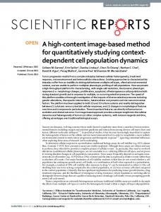
This activity originates from UWE. During the Application modeling functional and nonfunctional requirements are described, resulting in a WEBSITE MODEL and CMS MODEL. This activity also originates from UWE. An important activity is the Translation of features to components. Finally, the ADDITIONAL REQUIREMENTS are described. GX uses an adapted categorization found in the Guide to software requirements specifications (IEEE 1998), which is also used in WEM. It consists of support, security, system performance, scalability, interface and design conditions. In Figure 6, we visualize a high-level overview of the GX WebManager architecture. Several components are depicted, such as content management, interaction management, connectivity management, and workflow. These components are built in Siteworks, GX’s virtual machine in which applications are running. They have several connections to Java and other environments, to accommodate and leverage those platforms (van Berkum et al. 2004). In Figure 6, we also visualize the subactivity Translation of features to components, which is part of the Application modeling component. Three features, extracted from existing requirements documents, are listed. They are connected with arrows to indicate the direct translation to the corresponding components. Please note that this activity can also be conducted with other applications besides GX WebManager, since there is a certain amount
I. van de Weerd et al.
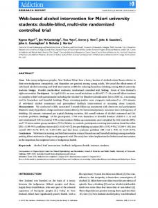
of standard functionalities available in web-based CMS applications. With this visualization, we show the difference in handling standard and complex requirements. In Figure 8, this process is also illustrated for complex requirements. 4.4. Complex Route The complex definition route consists of six main activities, as can be seen in Figure 7. First of all, an Extensive requirements elicitation is performed. On the basis of the findings of this process, the requirements are described. This activity originates from UWE. Then, the requirements analysis is based on the product vision of the web application to be built. In a perfect situation, the client writes this product vision himself, identifying TARGETS, ASSUMPTIONS, and SCOPE. However, in practice a consultant writes this document, here listed as GOALSETTING, after acquiring information from the customer. In line with the Acquisition phase, the FEATURES are updated here. This subactivity originates from the Unified Process. Thirdly, Domain modeling is used to create a common ground; that is, the TERMS with its RELATIONS need to be defined, in order to come to a conceptual object model. This DOMAIN MODEL is the base of all other activities. Fourthly, the Use case modeling starts. In a USE CASE DIAGRAM, all ACTORS and their functions
Figure 6. Translation of functionalities to GX WebManager components Copyright 2006 John Wiley & Sons, Ltd.
532
Softw. Process Improve. Pract., 2006; 11: 521–538 DOI: 10.1002/spip
Research Section
Method Engineering and Validation in Practice
Figure 7. Process-data diagram of the complex definition phase
Copyright 2006 John Wiley & Sons, Ltd. DOI: 10.1002/spip
Softw. Process Improve. Pract., 2006; 11: 521–538
533
Research Section
I. van de Weerd et al.
Figure 8. Translation of requirements to use cases
(the USE CASES) are described. This fragment originates from the Unified Process. A distinction is made between requirements that can be captured in standard WebManager components and custom use cases. In Figure 6, we showed how standard requirements are translated into WebManager components. Figure 8 illustrates how a complex requirement is translated into use cases. We listed two complex requirements, extracted from an existing requirements document, and connected them with the corresponding use cases. One of the requirements, namely, ‘Handle questions and complaints’ is further described in the use case. During the fifth activity, Application modeling, the web application that needs to be developed is described in terms of USER INTERFACE, NAVIGATION etc. This method fragment originates from UWE. Then, the ADDITIONAL REQUIREMENTS are described. This is done in the same way as in the standard route, using the Guide to software requirements specifications (IEEE 1998). The last activity is the Requirements validation. This can be done by using existing checklists, or by performing a walkthrough. This method fragment also originates from UWE.
two case studies have been carried out to test the new method; one case study to test the definition phase in the standard route, and one to test the definition phase in the complex route.
5. VALIDATION
Resulting from the expert validation, parts of WEM were implemented in the organization. This was done through writing templates, organizing workshops for the consultants and project managers and publishing WEM information in the intranet of
We applied two types of validation. Firstly, expert validations were carried out for both the standard and complex routes of the definition phase. Also, Copyright 2006 John Wiley & Sons, Ltd.
534
5.1. Expert Validation WEM was developed with inputs from the requirements management workgroup, consisting of consultants and project managers of GX and one external consultant. The goal of this workgroup was an overall improvement in the requirements process at GX. WEM was assessed in this workgroup. Two routes of the method were validated, namely, the standard and complex routes. The results were positive, for the following reasons: • The distinction of standard and complex implementation situations was perceived as very useful for the execution of projects. • The use of user and domain modeling in the standard route was seen as very practical. • Use case modeling in the complex route was seen as (a) very useful for a better communication with the customer and (b) a good way of thoroughly documenting the requirements.
Softw. Process Improve. Pract., 2006; 11: 521–538 DOI: 10.1002/spip
Research Section
GX. In time, the method will also be distributed to GX’s implementation partners. 5.2. Case Study: Standard Route 5.2.1. Overview The standard route was tested in a project that consisted of building an intranet for a large health insurance organization in the Netherlands. The intranet is used as a communication device and information source for the employees of the organization. The project had an estimated budget of 800 man-hours. The stakeholders consisted of the project team of GX, namely: (a) project manager, (b) consultant, (c) architect and (d) developer; and a project team at the heath care organization: (a) project manager, (b) innovation advisor, (c) advisor new media. Before the project started, a briefing was given to the GX project team to outline the new methods. The requirements document consisted of 26 pages. Four different users were identified, namely (a) employee, (b) editor, (c) administrator and (d) web master. The definition phase of the development cycle was finished successfully. At the time of writing this article, the application is being completed by the software engineers. 5.2.2. Evaluation The standard route was evaluated by conducting interviews at the GX project team, and by sending a questionnaire to the customer project team. The GX team responded positively. The structure and coherence of the sections were assessed to be logical and clear. This Requirements Document was perceived as an improvement compared to the earlier one. One drawback was that the translation of features to components was not seen as really useful to the engineers. The project team of the customer organization was asked to fill out a questionnaire1 . Both the requirements process and document were assessed. The questions on the requirements process consisted of three categories: (a) structure, (b) team, and (c) general. Following, the questions on the requirements document were divided into the following categories: (a) understandability, (b) correctness, (c) coherence, and (d) general. 1
http://www.cs.uu.nl/people/weerd/standard.php
Copyright 2006 John Wiley & Sons, Ltd. DOI: 10.1002/spip
Method Engineering and Validation in Practice
Four project members answered the questionnaire. The answers were quite positive with a mean score of 3.8 on a Likert scale of 1 (most negative) to 5 (most positive). The requirements process part received a mean score of 4.1. The given answers ranged from neutral to very good. The answers on the requirements document questions were a little less positive, with a mean score of 3.6, ranging from not so good to very good. Understandability and correctness of the system were given good scores. However, coherence scored a little lower, ranging from not so good to good. Especially the translation of functionalities to WebManager components received a low score. The remark was made that some of these functionalities should better be expressed in use cases. As one of the project members stated: ‘I would like to see a more concrete analysis. Use cases are a good technique; you should use these more often’. This might imply that the complex route would have been a better choice. However, other project members did not have this problem. In summary, the results were quite positive. The document was logical and understandable. However, both the GX project team and customer project team commented on the translation of functionalities to WebManager components as a potential problem area. 5.3. Case Study: Complex Route 5.3.1. Overview The complex route was piloted in a project that consisted of building a web application for a large telecommunication organization in the Netherlands. The purpose of the web application was to support the testing of new products and services that are offered to a limited group of customers in a limited period of time. Employees of the organization should be able to develop and test a new offer with the application, without the help of GX. Several connections with existing back-office systems had to be realized. Also, online payment of the products and services had to be supported. Finally, a special application for the Customer Care department needed to be developed, in order to support this department with customer service. The project had an estimated budget of 400 manhours. Several stakeholders were involved in the requirements phase of the project. At the side of GX these were: (a) project manager, (b) consultants, and Softw. Process Improve. Pract., 2006; 11: 521–538
535
Research Section
(c) software architect. Stakeholders of the customer organization were: (a) business project manager, (b) technical project manager, (c) web department manager, and (d) Customer Care project manager. The requirements document consisted of 32 pages. The use case model consisted of seven actors, who were connected to 17 use cases. Eight of these use cases were immediately translated to standard GX WebManager components. The others were more complex and were provided with use case descriptions. One part of the method was omitted, namely, the drawing of a class diagram to model the domain, since its use was not necessary in this project. During the development, few changes were made to the requirements. This led to a web application finished within time and budget. 5.3.2. Evaluation The requirements document was send to the all stakeholders at GX and the customer organization. In an interview, the GX project team responded positively to the new method. In comparison to the old method, WEM was more structured and better able to describe complex functionalities. Also, the domain modeling was commented on as being ‘clarifying and useful’. A remark was made on the use of a feature list, which was not recognized as useful. Another comment was that use case modeling is time-consuming. However, the budgeted hours for this project were not exceeded. All stakeholders agreed that this document was an improvement over former requirements documents. To the customer organization project members, a questionnaire2 was send. The questions were divided in several categories. First, questions on the requirements process were asked in the categories (a) structure, (b) team, and (c) general. Then, questions on the requirements document were asked in the categories (a) understandability, (b) correctness, (c) use case modeling, and (d) general. The questionnaire was answered by three project members. The answers appeared to be overwhelmingly positive. As the project manager commented: ‘My compliments for the requirements document. It is very understandable and readable, also for people with no technical background and for people who need to review the document without preparation.’ On a Likert scale of 1 (most negative) to 5 (most positive), a mean score of 4.4 was received. The given 2
http://www.cs.uu.nl/people/weerd/complex.php
Copyright 2006 John Wiley & Sons, Ltd.
536
I. van de Weerd et al.
answer ranged from 3 to 5. No significant difference in scores was measured between the ‘process part’ and ‘document part’. In summary, the requirements document was ‘understandable and logical’, with the right level of detail. Also, the functionalities described in the use cases perfectly matched the functionalities that they wanted to be realized. Use cases were considered to be a great way to describe functionalities, since they are understandable for technical and nontechnical project members. 5.4. Further Discussion In summary, the results of the expert validation and case studies were positive. The complex route received slightly better scores than the standard route. On the basis of the results, the following comments should be made: First of all, in both case studies only the definition phase was covered, which implies that the acquisition phase was done in the ‘old-fashioned’ way. The most obvious consequence was that the feature list, which should have been created in the acquisition phase and used in the definition phase, was seen as redundant by the consultants. Both customer organizations, however, did not comment on this. Concerning the complex route, all project members at the customer’s organization were familiar with use case modeling. If they were not, the requirements document might have been more difficult to understand. Using the method may lead to new insights. The developed method is not static, but dynamic. Users of the method should adapt it to their own preferences. When it appears that an activity structurally is omitted, the method should be updated accordingly.
6. CONCLUSIONS The scientific contribution of this article is twofold. First, an improvement is proposed to the existing approaches to situational method engineering. The described process helps in developing a method base, consisting of candidate methods that are selected based on how they meet the identified implementation situation needs. Secondly, looking at the delivered results of the research, a method Softw. Process Improve. Pract., 2006; 11: 521–538 DOI: 10.1002/spip
Research Section
has been engineered and validated for the process of implementing web-based CMS applications: the WEM. This method can be used for standard and complex implementation situations, by following the described routes in the route map. Since no such method existed, this research is an important addition to the existing information systems and web development methods. To support the engineering approach method, we applied a meta-modeling technique, the so-called process-data diagram. By modeling the relations between activities and concepts, it is possible to engineer both process and data perspective of the method. This process-data diagramming technique is currently applied in more cases, to improve, update, and keep it consistent with the evolving UML standards. A limitation of WEM is that currently only the acquisition, definition, orientation, and analysis phases are covered. In addition, only the definition phase was validated. However, the results were promising. In future work, the method should be expanded and refined, based on experiences in executed projects. Also, besides the Unified Process and UWE, other relevant methods can be analyzed to improve the method base. Finally, a challenge lies in the integration of the method into the GX WebManager product. As the content management system itself is capable of storing structured documents, it makes sense to integrate the WEM design method as an extension of the WebManager product. This strategy is similar to the extension of the Oracle DBMS with Oracle CASE tools, or of the Baan ERP software with the Dynamic Enterprise Modeling (DEM) tooling (Brinkkemper 1998). ACKNOWLEDGEMENTS The authors wish to thank Roel Bouwmans, Ren´e Janssen, and Bob Kennedy for providing inputs to WEM during its development. We also thank Nils ten Broeke, Christiaan Hoogerwerf, Michel Teunissen, Patrick Hendriks, Michael Albin, and the rest of the project teams who developed the web applications, as described in the validation, and for their contributions in the validation of this article. We also thank the project team members of both customer organizations for their cooperation in testing and validating WEM. Copyright 2006 John Wiley & Sons, Ltd. DOI: 10.1002/spip
Method Engineering and Validation in Practice
Finally, we would like to thank the anonymous reviewers for their extensive remarks that led to the improvement of this article.
REFERENCES Aydin MN, Harmsen F. 2002. Making a Method Work for a Project Situation in the Context of CMM. Lecture Notes in Computer Science 2559, Springer Berlin: Heidelberg, 158–171, DOI: 10.1109/ICSE.2003.1201204. Baresi L, Garzotto F, Paolini P. 2001. Extending UML for modeling web applications. Proceedings of the 34th Annual Hawaii International Conference on System Sciences (HICSS). IEEE Computer Society: Los Alamitos, CA, USA, DOI: 10.1109/HICSS.2001.926350. Baumeister H, Koch N, Mandel L. 1999. Towards a UML extension for hypermedia design. Proceedings ‘‘UML’’ ‘99, Lecture Notes in Computer Science 1723, Springer Berlin: Heidelberg, 614–629. van Berkum M, Brinkkemper S, Meyer A. 2004. A combined runtime environment and web-based development environment for web application engineering. Proceedings of the 16th International Conference on Advanced Information Systems Engineering (CAiSE 2004), Lecture Notes in Computer Science 3084, Springer Berlin: Heidelberg, 307–321, DOI: 10.1007/b98058. Brinkkemper S. 1996. Method engineering: engineering of information systems development methods and tools. Information and Software Technology 38(4): 275–280. Brinkkemper S. 1998. Global process management. Dynamic Enterprise Innovation: Establishing Continuous Improvement in Business, Baan Business Innovation: Putten, The Netherlands, 4-8–4-15. Burzagli L, Billi M, Gabbanini F, Graziani P, Palchetti E. 2004. The use of current content management systems for accessibility. Proceedings of the 9th International Conference on Computers Helping People with Special Needs (ICCHP 2004), Lecture Notes in Computer Science 311, Springer Berlin: Heidelberg, 331–338. Ceri S, Fraternali P, Bongio A. 2000. Web Modeling Language (WebML): A modeling language for designing web sites. Computer Networks 33: 137–157, DOI: 10.1016/S1389-1286(00)00040-2. Chen PP. 1976. The entity-relationship model–Towards a unified view of data. ACM Transactions on Database Systems 1(1): 9–36. De Troyer OMF, Leune CJ. 1998. WSDM: A user-centered design method for web sites. Computer Networks and ISDN Systems 30(1): 85–94, DOI: 10.1016/S0169-7552(98)000427. Softw. Process Improve. Pract., 2006; 11: 521–538
537
Research Section
Dietzsch A. 2002. Adapting the UML to business modelling’s needs–experiences in situational method engineering. > 2002–Proceedings of the Unified Modeling Language; Fifth International Conference. Springer: Dresden, Germany, 73–83. Escalona MJ, Koch N. 2004. Requirements engineering for web applications: A comparative study. Journal on Web Engineering, Vol. 2(3). Rinton Press: Princeton, New Jersey, 193–212. Gnaho C. 2001. Web-Based Information Systems Development–A User Centered Engineering Approach. Lecture Notes in Computer Science 2016, Springer Berlin: Heidelberg, 105–118. IEEE. 1998. Std. 830–1998 Guide to Software Requirements Specifications (ANSI). Resource and Technique Standards. Vol. 4. The Institute of Electrical and Electronics Engineers, Inc. IEEE Software Engineering Standards Collection: New York, USA. Jacobson I, Booch G, Rumbaugh J. 1999. The Unified Software Development Process. Addison Wesley Longman Publishing Co., Inc: Redwood City, CA. Karlsson F. 2002. Bridging the gap between method for method configuration and situational method engineering. Promote IT. Skovde: Sweden. ¨ ˚ Karlsson F, Agerfalk PJ. 2004. Method configuration: Adapting to situational characteristics while creating reusable assets. Information and Software Technology 46(9): 619–633. Koch N. 2001. Software engineering for adaptive Hypermedia applications. Phd Thesis, Uni-Druck Publishing Company, Austria, Munich. Kumar K, Welke RJ. 1992. Methodology engineering: A proposal for situation specific methodology construction. Challenges and Strategies for Research in Systems Development. John Wiley and Sons: Washington, DC, 257–269. Larman C, Kruchten P, Bittner K. 2001. How to Fail with the Rational Unified Process: Seven Steps to Pain and Suffering. Valtech Technologies & Rational Software.
I. van de Weerd et al.
2003. Available from the Object Management Group website: www.omg.org. Ralyt´e J, Deneck`ere R, Rolland C. 2003. Towards a Generic Model for Situational Method Engineering. Lecture Notes in Computer Science 2681, Springer Berlin: Heidelberg, 95. Robertson R. 2003. So, what is a content management system? KM Column. Step Two Designs Pty Ltd. http://www.steptwo.com.au/papers/kmc what/pdf/ KMC What.pdf, accessed 12/01/06. Rossi M, Subramah M, Lyytinen K, Kaipala J, Tolvanen JP. 2000. Method rationale in method engineering. Proceedings of the 33rd Annual Hawaii International Conference on Systems Science. IEEE Computer Society Press: New York, USA, DOI: 10.1109/HICSS.2000.926680. Sauer S, Engels G. 1999. Extending UML for modeling of multimedia applications. In Proceedings of the IEEE Symposium on Visual Languages, 80, DOI: 10.1109/VL.1999.795878. Saeki M. 2003. Embedding metrics into information systems development methods: an application of method engineering technique. In CAiSE 2003: The 15th Conference on Advanced Information Systems Engineering, 374–389. van Slooten K, Brinkkemper S. 1993. A method engineering approach to information systems development. In Information Systems Development Process, 167–186. van Slooten K, Hodes B. 1996. Characterizing IS development projects. Method Engineering: Principles of method construction and tool support. Proceedings of the IFIP TC8, WG8.7/8.2 Working Conference on Method Engineering, Atlanta, GA. Souer J, van der Weerd I, Versendaal J, Brinkkemper S. 2005. Situational Requirements Engineering for the Development of Content Management System – based Web Applications. Accepted for a publication in the International Journal of Web Engineering and Technology (IJWET). Vaishnavi V, Kuechler W. 2004. Design Research in Information Systems. http://www.isworld.org/ Researchdesign/drisISworld.htm, accessed 12/01/06.
Lowe D, Henderson-Sellers B. 2001. Characteristics of Web Development Processes.In Proceedings of SSGRR2001: International Conference on Advances in Infrastructure for Electronic Business, Science and Education on the Internet, Scuola Superiore Guglielmo Reiss Romoli, Italy, 21.
Vidgen R, Goodwin S, Barnes S. 2001. Web Content Management. In Proceedings of the 14th International Electronic Commerce Conference, Bled, Slovenia, 465–480.
March S, Smith G. 1995. Design and natural science research on information technology. Decision Support Systems 15: 251–266, DOI: 10.1016/0167-9236(94)00041-2.
van de Weerd I. 2005. WEM: A design method for CMS-based web implementations. Technical report UUCS-2005-043. University of Utrecht, Department of Information and Computing Sciences: Utrecht, The Netherlands.
OMG. 2003. UML 2.0 Superstructure final adopted specification, Document reference ptc/04-10-02 August Copyright 2006 John Wiley & Sons, Ltd.
538
Softw. Process Improve. Pract., 2006; 11: 521–538 DOI: 10.1002/spip