A software-based system for interactive spatial sound synthesis Elizabeth M. Wenzel Human Factors R & T Div. NASA Ames Research Center Mail Stop 262-2 Moffett Field, CA 94035 USA +1 650 604 6290
[email protected]
Joel D. Miller Jonathan S. Abel Raytheon STX Corp. San Jose State Univ. Foundation NASA Ames Research Center NASA Ames Research Center Mail Stop 262-2 Mail Stop 262-2 Moffett Field, CA 94035 USA Moffett Field, CA 94035 USA +1 650 604 3926 +1 650 604 5198
[email protected] [email protected]
ABSTRACT This paper discusses development issues for a software-based, real-time virtual audio rendering system, Sound Lab (SLAB), designed to work in the personal computer environment using a standard signal-processing library. The system, which is being developed as a tool for the study of spatial hearing, takes advantage of the low-cost PC platform while providing a flexible, maintainable, and extensible architecture to enable the quick development of experiments. The current capabilities and dynamic behavior of the SLAB system are described. Keywords Spatial sound, interactive virtual audio, real-time synthesis INTRODUCTION Interest in the simulation of acoustic environments has prompted a number of technology development efforts for applications such as auralization of concert halls and listening rooms, virtual reality, spatial information displays in aviation, and better sound effects for video games. Each of these applications imply different task requirements or emphasize different aspects of the listening experience that, in turn, require different approaches in the development of rendering software and hardware. Virtual reality applications such as astronaut training environments, where both good directional information and a sense of presence in the environment are desired, may have requirements for both information accuracy and some degree of authenticity or realism. Achieving these two aspects of the simulation requires that head tracking be enabled with special attention devoted to the dynamic response of the system. For example, a relatively high update rate (about 60 Hz) and low latency (less than about 100 ms) may be required in order to optimize localization cues from head motion as well as provide a smooth and responsive simulation of a moving listener and/or sound source [9, 11-13]. Implementing a perceptually adequate dynamic response is computationally intensive and typically requires an array of dedicated digital signal processors and one or more host computers. Development of efficient synthesis techniques could benefit from further research that specifies the perceptual fidelity required for adequate rendering [e.g., 1, 2]. For example, it is commonly assumed that only the direct-path head-related transfer functions (HRTFs) need to be rendered at the highest possible fidelity while early reflections may be rendered with less fidelity, i.e., fewer filter coefficients [10]. However, the number of coefficients actually used is often based on a designer's best guess and the limitations of a particular system, rather than on the outcome of perceptual studies. Such studies could give the designers of such systems better guidance regarding where to devote computational resources with better assurance that perceptual validity is not being sacrificed. The goal of the system described here, Sound Lab (SLAB), is to provide an experimental platform with low-level control of a variety of signal-processing parameters for conducting such studies. The project is also an attempt to provide the basis for a low-cost, software-based system for dynamic synthesis of virtual audio over headphones that does not require an array of special purpose signal processing hardware. Because it has been designed for the Windows platform and relies on a standard signal-processing library, it can more readily take advantage of improvements in processing power without extensive software revisions. The development of SLAB is currently a work-in-progress. This paper outlines the overall design goals of the system and describes progress to date in implementation. DESIGN CHARACTERISTICS OF SOUND LAB The SLAB system was designed to allow control over the kinds of spatialization parameters studied in psychoacoustic studies while providing a quick experiment development cycle. The system features a modular, object-oriented design that provides the flexibility and extensibility needed to accommodate a wide range of experiments. This design approach has the additional benefit of easing maintenance requirements.
Because of its modularity, SLAB can support a wide variety of signal flow structures without extensive software revisions. Currently, the "auralization unit" (see below) has a fixed architecture, consisting of a set of parallel signal paths from each source to the listener. Parameters determining the processing (delay line indices, filter coefficients, and the like) are computed based on the experiment state (defined by quantities such as source and listener position), and applied to the signal flow. In this way, the signal flow may be optimized for processing efficiency and latency, independent of the experiment. Since only certain aspects of the translation of experimental state to signal processing parameters change from study to study, development time is minimized. In contrast to an extremely flexible but computationally intensive system like the Spatialisateur [5] that uses a graphical signal processing software environment, SLAB's fixed signal flow architecture can be thought of as a compromise solution that optimizes efficiency at the expense of complete flexibility. Such a compromise is necessary given the design goal of providing a software solution for a low-cost host platform (e.g., Intel Pentium). SLAB Signal Processing There are three domains in the physical scenario to be rendered as envisioned here: the source, the environment, and the listener. A source, characterized by its waveform, level, radiation pattern, size, and dynamic quantities including position and orientation, radiates into an environment. Propagation of acoustic energy in the environment is specified by the speed of sound, spherical spreading loss, and air absorption; the environment is further specified by the location and characteristics of reflecting and transmitting objects. The source signal propagates through the environment, arriving at a listener characterized by a head-related impulse response (HRIR) and interaural time delay (ITD), as well as a dynamically changing position and orientation. The HRIRs used here are derived from minimum-phase representations of the raw left and right-ear impulse responses measured for individual subjects. ITDs are estimated from the raw left and right-ear impulse responses and represented as a pure delay. HRTFs, on the other hand, refer to the equivalent frequency domain representations of the raw HRIRs.
Physical Signal Flow SOURCE RADIATION
HEAD EFFECT
ENVIRONMENT PROPAGATION
source
mix
1
r(z)
radiation pattern
P
z−τα a(z)
propagation delay air absorption spherical spreading
−τh
m(z) P
P
surface reflection object transmission
z
h(z)
+ 2P
2
binaural signal
interaural time delay left, right HRIR
P = Number of Paths (Direct Path & Reflections); 2P = Paths Rendered for Left & Right Ears
(a)
SLAB Signal Flow source
1
z
−τa ± τh
interpolated delay line propagation delay ITD
(b)
headphone output
mix
2P
m(z) IIR filter, m reflection transmission
2P
h(z) a(z) r(z) FIR filter radiation pattern air absorption spherical spreading HRIR
2P
+
2
e(z)
2
IIR filter output device equalization
P = Number of Paths (Direct Path & Reflections); 2P = Paths Rendered for Left & Right Ears
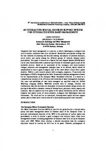
Fig.1. (a) The physical signal flow is shown as a block diagram that partitions the properties of the physical scenario into the relevant signal processing components. (b) The SLAB signal flow, or "auralization unit," partitions the physical scenario into signal processing components as they are implemented in the SLAB system architecture. A signal path may be modeled according to the physical scenario using the signal flow architecture shown in Fig. 1(a). A set of P paths from the source to the listener (including the direct path) is separately rendered. The filter r(z) imposes the source radiation pattern on the source signal to take the signal from the source to a point in the vicinity of the source along a particular radiation direction. The filter z-τα a(z) applies the propagation delay, spherical spreading loss, and air absorption experienced as the source signal propagates from near the source to near the listener; the filter m(z) imposes transmission or reflection characteristics of any objects encountered. The filter z-τh h(z) represents the HRIR and ITD, and takes any arriving signal from the vicinity of the listener along a particular direction to the listener's ear canals.
The SLAB signal flow shown in Fig. 1(b) was designed to implement the physical effects discussed above in an easily maintained, efficient architecture. It consists of a set of parallel signal paths, one for each rendered path from the source to a listener's ears. The propagation delay and interaural time delay for each source-to-ear path are combined, and implemented via an interpolated delay line. Static effects along each path, such as materials reflection filtering are combined and implemented as an infinite impulse response (IIR) filter. A finite impulse response (FIR) filter is used to implement dynamic effects such as the head-related impulse response and the source radiation pattern. Interpolated delay line The interpolated delay line provides a fractionally indexed delay representing propagation delay and interaural time delay. The fractional delay line is implemented by linearly interpolating between adjacent samples of a two-times up-sampled source signal. Linear interpolation is used for its computational simplicity; each fractional sample evaluated requires only two multiplyaccumulates. However, linear interpolation of the input source signal samples as described in [10] results in a low-pass filtering for delays near odd half integers (e.g., -6 dB at 15 kHz for a fractional delay of one-half the sampling interval). By contrast, a linearly interpolated, up-sampled delay exhibits noticeably less high-frequency attenuation (e.g., -1 dB or less at 15 kHz for all fractional delays). Since the input signal needs to be up-sampled only once, the additional computational cost is fixed and small compared with the cost of linearly interpolating indices for even a small number of paths. The factor of two up-sampling was used because it provided a sufficiently flat magnitude spectrum, was inexpensive to compute, and fit within the memory budget. IIR filter (static scenario properties) The SLAB signal flow uses an IIR filter in each path to implement static filtering, such as that imposed by a materials reflection. IIR filters are very difficult to change over time without producing filter instabilities that cause audible artifacts [5]. Thus, they are not suitable for implementing time-varying properties. Static properties, on the other hand, can usually be implemented much more efficiently with an IIR filter than with an FIR filter. For instance, many materials are characterized by reflections that are attenuated above a transition frequency, often below 1000 Hz. A low-order IIR filter is sufficient to model such materials, but because the transition frequency is such a small fraction of the sampling rate, the corresponding FIR implementation would require a large number of taps to adequately represent the required low-frequency detail. Note that, because of the use of a fixed IIR materials filter, SLAB is limited to specular reflections (angle of incidence equals angle of reflection) in which the filtering is independent of the direction of arrival. FIR filter (dynamic scenario properties) The SLAB FIR filter implements dynamically changing effects, including the source radiation pattern, air absorption, spherical spreading loss, and head-related impulse response. The FIR filter coefficients for a given path are formed by convolving the impulse responses of the effects rendered, and windowing the resulting impulse response to the FIR filter length for that path. Having a single FIR filter allows any number of effects to be rendered using the same optimized signal processing structure. However, care should be taken that the cascade of effects does not result in an impulse response that is much longer than the computational constraints allow. To compute the source directivity filter for a given path from the source to listener ear, a table of impulse responses for the source radiation pattern is indexed according to the radiation direction. Source radiation-pattern impulse responses are tabulated on a grid in azimuth and elevation relative to the source, with the same number of azimuths at each elevation. A four-way linear interpolation is used to form the radiation pattern impulse response, h (t; θ, φ), associated with a given radiation azimuth θ and elevation φ. h (t; θ, φ) = αφ αθ g(t; θ2, φ2) + αφ (1-αθ ) g(t; θ1, φ2) + (1-αφ ) αθ g(t; θ2, φ1) + (1-αφ ) (1-αθ ) g(t; θ1, φ1).
(1)
The g(t; θ k , φk ) represent tabulated impulse responses; θ1 and θ 2 are the tabulated azimuths immediately smaller and immediately larger than the input azimuth θ; and φ1 and φ2 are the tabulated elevations immediately smaller and immediately larger than the input elevation φ. The factors α are fractions representing the distance between the indexed azimuth and elevation and the interpolated azimuth and elevation: αφ = (φ − φ1) / (φ2 − φ1) and αθ = (θ − θ1) / (θ2 − θ1). 2
2 –1/2
(2)
Spherical spreading loss is computed as (1 + ρ / σ ) , where ρ is the source distance from the listener, and σ is the source size. This characteristic closely approximates that of a planar baffled cylindrical piston of radius σ [7].
The head-related impulse response for a particular path's arrival angle is computed via table look-up in a manner similar to that of the source radiation pattern. Due to the greater complexity of HRIRs, however, the table measurement grid has many more azimuth entries. As noted above, the HRIRs used here are minimum-phase representations of the raw left and right-ear impulse responses measured for individual subjects using a blocked-meatus technique [modified Crystal River Engineering "Snapshot" system, e.g., 2]. ITDs are estimated from the raw left and right-ear impulse responses and represented as a separate table of location-dependent pure delays. To form the HRIR and ITD for an arbitrary source azimuth and elevation, the four nearest database neighbors are linearly interpolated in real time. This results in a 128-tap FIR filter that is applied to the output of the materials filters. 128-tap filters are currently the maximum fidelity that can be reasonably achieved for the direct path with a single Pentium II processor rendering a direct path and six 32-tap reflections (see below). There is no inherent limitation on the number of coefficients in SLAB, other than the host's processing power. Mixing and equalization Prior to headphone presentation, the outputs of the direct path and early reflection signal processing paths are summed to form a stereo output pair by a mixer having a 32-bit integer accumulator. It should be noted that, currently the SLAB system uses HRIRs that have been equalized prior to storage in the database. As a result, the output equalization filter shown in Fig. 1(b) is currently a pass-through component. Dynamic Behavior Interactive virtual audio systems are necessarily time varying. As the scenario changes over time, different signal processing parameters are required to render the changing physical effects imposed on the source signal. The difficulty is that all signal processing structures available for implementing the changing scenario are inherently static, assuming fixed coefficients. As a result, care must be taken when updating signal processing parameters. Ideally, new parameters are switched in sufficiently frequently that the change from one parameter set to the next is imperceptibly small. Certain parameters such as time delays need to be updated every sample to avoid artifacts; minimum-phase head-related impulse responses are somewhat more forgiving. A primary problem with this approach is that it is expensive to compute signal processing parameters from scenario information. There is also the additional issue that peripherals such as head trackers typically provide update rates ranging from 30 to 120 Hz, so that intermediate scenario data must be developed. Two methods are typically used to accommodate a changing scenario: output crossfading, and parameter crossfading (described as commutation in [5]). In output crossfading (e.g., as in early versions of the Convolvotron that used nonminimum phase HRIRs), the output is a blend of the input processed once according to past parameters and then again according to present parameters. While the two processing paths use static coefficients, the blend is varied over time to achieve a transition between the parameter sets. Parameter crossfading, by contrast, processes the input only once according to a varying set of rendering parameters that have been crossfaded before processing of the input signal. Overlap-add methods that operate in the frequency domain are, in effect, a type of output crossfade where the crossfade interval corresponds to the overlap-add interval. Undesirable artifacts when updating the scenario are mitigated by the use of frequent updates and densely measured HRTF databases and/or densely pre-computed binaural room impulse responses [3, 4]. Disadvantages of this method include large memory requirements and the fact that changes in the source, room and receiver characteristics require new measurements or simulations. Other systems utilizing convolution in the time-domain also appear to have used densely-interpolated HRIR databases (e.g., spatial resolution on the order of 2° after interpolation), perhaps combined with a short period of output crossfade, to mitigate possible artifacts due to switching between filters [8, 9]. Output crossfading has the drawback of being computationally burdensome. In addition, the output is a mixture of two different systems and might not resemble that of a single system intermediate between the two. Accordingly, the SLAB system uses a variation of parameter crossfading that we term "parameter tracking." Since new scenario information may be available relatively infrequently and contains measurement noise, signal processing parameters computed with each new scenario update become target parameters that are tracked or smoothed. Currently in the SLAB system, the scenario is updated rather frequently compared to other systems (i.e., at an average interval of about 8.3 ms given a 120 Hz scenario update rate). In parameter crossfading, there may be multiple update rates for various signal processing parameters. In SLAB, there are two parameter update rates. Every other input frame or 1.45 ms (64 samples), filter coefficients are replaced with ones slightly closer to the target coefficients, while path delays are updated every sample (22.7 µs) to preserve embedded Doppler shifts. A more detailed discussion of dynamic synthesis methods in SLAB and other systems can be found in [14]. THE CURRENT SLAB SYSTEM IMPLEMENTATION As mentioned in the introduction, the SLAB system is a work-in-progress. While the signal flow architecture illustrated in Fig. 1(b) has not yet been fully implemented, significant progress has been made in developing the modular software
architecture to support its full implementation. To date, the components of the signal processing architecture that have been implemented include the interpolated delay line and the spherical spreading loss and HRIR components of the FIR filter. As described previously [6], these components have been utilized in an initial simulation scenario based on the image model with a direct path and six first-order reflections. Scenario specifications and current performance characteristics achievable with a single 450 MHz Pentium II processor running Windows 98 are summarized in Table 1. Simulation Scenario Specifications Rectangular room; Image model Number of first-order reflections: 6 Number of direct path FIR taps: 128 Number of reflection FIR taps: 32
System Dynamics Sample Rate: 44.1 kHz Internal system latency: 24 ms Scenario update rate: 120 Hz Delay line update: every sample (22.7 µs) DSP coefficient update: every 64 samples (1.45 ms)
Table 1. Simulation scenario and performance characteristics for an initial implementation using the SLAB system. One of the major implementation hurdles overcome in developing such a system has been to achieve adequate dynamic performance in Windows, an environment that is not ideally suited to real-time performance. A measurement of the internal latency of SLAB for the simulation described above provides a preliminary assessment of its dynamic performance. The internal latency is the delay between acquisition of location data by the host rendering system and the rendered audio output. Total system latency, or end-to-end latency, on the other hand, refers to the time elapsed from the transduction of an event or action, such as movement of the head, until the consequences of that action cause the equivalent change in the virtual sound source location. Latencies are contributed by individual components of a virtual audio system, including tracking devices, signal processors, software to control these devices, and communications lines [11-13]. Here, internal latency was measured in the following manner. An I/O port of the SLAB host renderer and the SLAB headphone output were connected to the begin- and end-time inputs of an interval timer, respectively. The I/O port was used to indicate when new scenario information was received by the SLAB host rendering system. With this configuration, the internal latency measurement was 24 ms. A preliminary value of 24 ms is quite encouraging considering the inherent difficulties in managing low-latency Windows audio output, let alone while performing a high cost simulation that consumes a significant portion of available system resources. The total system latency would necessarily be somewhat longer than 24 ms since it would include additional head-tracker, communication line, and client/server latencies. The parameter tracking method used to smooth time-varying parameters also contributes an additional latency that is dependent upon the time constant chosen for the integrator (see [14] for details). Implementation of the full signal path of Fig. 1(b) will no doubt also add to the latency of the system, although it is unclear how significant this increase might be, particularly since the signal processing algorithms have yet to be fully optimized. CONCLUSIONS AND FUTURE DIRECTIONS The goal of the system described here, Sound Lab (SLAB), is to provide a software-based experimental platform with lowlevel control of a variety of signal-processing parameters for conducting psychoacoustic studies. For example, some of the parameters that can be examined in future studies of spatial audio include the number, fidelity (number of filter taps) and positioning (correct vs. incorrect) of reflections. System latency and update rate can also be manipulated. To date, the components of the signal processing architecture that have been implemented include the interpolated delay line and the spherical spreading loss and HRIR components of the FIR filter. These components have been utilized in an interactive simulation scenario based on the image model with a direct path and six first-order reflections. The scenario was implemented using C++ on a single 450 MHz Pentium II running Windows 98. DirectSound was used to achieve low latency audio output. One of the major implementation hurdles has been achieving adequate dynamic performance in the Windows environment. Measurement of the internal latency of the system provides a preliminary assessment of the dynamic performance of SLAB. This preliminary value of 24 ms is quite encouraging considering the inherent difficulties in managing low-latency Windows audio output. Informal listening tests indicate that the dynamic behavior of the system is both smooth and responsive. The smoothness is enhanced by the 120-Hz scenario update rate, as well as the parameter tracking method which produces rather high parameter update rates; i.e., time delays are updated at 44.1 kHz and the FIR filter coefficients are updated at 690 Hz. The responsiveness of the system is enhanced by the low latency of 24 ms. The scenario update rate, parameter update rates, and latency all compare favorably to other virtual audio systems [e.g., 3, 4, 8-10]. For example, the DIVA system [10] has a minimum internal latency of approximately 110 ms. About half of this latency is due to the buffering required to avoid audible discontinuities in a UNIX-based system and would be present for even the simplest auralization scenarios. Thus, problems in managing latency are not limited to the Windows operating system.
While the current scenario implemented in SLAB is incomplete, we don't expect implementation of the full signal path to significantly increase latency or decrease filter coefficient update rates. At this point, it is difficult to estimate the impact of simulating higher-order reflections or late reverberation on SLAB system performance. In addition to implementing the full signal path and optimizing the signal processing algorithms, future development will include exploration of several systems and performance issues. A client-server architecture has recently been implemented so that SLAB performance is preserved by isolating it from other system components, such as the experimental control software and the head tracker. Multiple processor support is also being researched as a method for increasing computational resources. In order to facilitate simulation of more complex room models in real time, SLAB could be implemented as a distributed system to further spread out the computational load over multiple workstations. ACKNOWLEDGEMENTS Work supported by the NASA Aerospace Operations Systems Program and by the Navy (SPAWARSYSCEN, San Diego). REFERENCES 1. Begault, D. R. Audible and inaudible early reflections: Thresholds for auralization system design. 100th Convention of the Audio Engineering Society, (Copenhagen, Denmark, 1996), Preprint 4244. 2. Begault, D. R., Wenzel, E. M., Lee, A. S., and Anderson, M. R. Direct comparison of the impact of head tracking, reverberation, and individualized head-related transfer functions on the spatial perception of a virtual speech source. 108th Convention of the Audio Engineering Society, (Paris, France, 2000), Preprint 5134. 3. Bronkhorst, A. W. Localization of real and virtual sources. Journal of the Acoustical Society of America, 98, (1995), 25422553. 4. Gardner, W. G. Efficient convolution without input-output delay. Journal of the Audio Engineering Society, (1995), 43, 127-136. 5. Jot, J. M., Larcher, V. and Warusfel, O. Digital signal processing issues in the context of binaural and transaural stereophony. 98th Convention of the Audio Engineering Society, (Paris, France, 1995), Preprint 3980. 6. Miller, J. D., Abel, J. S. and Wenzel, E. M Implementation issues in the development of a real-time, Windows-based system to study spatial hearing. Journal of the Acoustical Society of America, 105, (1999), 1193. 7. Pierce, A. Acoustics. Acoustical Society of America: New York, 1989, p. 219. 8. Sahrhage, J., Blauert, J. and Lehnert, H. Implementation of an auditory/tactile virtual environment. Proceedings of the 2nd FIVE International Conference, (Palazzo dei Congressi, Italy, 1996), 18-26. 9. Sandvad, J. 1996. Dynamic aspects of auditory virtual environments. 100th Convention of the Audio Engineering Society, Copenhagen, preprint 4226. 10. Savioja, L., Huopaniemi, J., Lokki, T. & Väänänen, R. Creating interactive virtual acoustic environments. Journal of the Audio Engineering Society, 47, (1999), 675-705. 11. Wenzel, E. M. Analysis of the role of update rate and system latency in interactive virtual acoustic environments. 103rd Convention of the Audio Engineering Society, (New York, NY, 1997), Preprint 4633. 12. Wenzel, E. M. The impact of system latency on dynamic performance in virtual acoustic environments. Proceedings of the 15th International Congress on Acoustics and 135th Meeting of the Acoustical Society of America, (Seattle, WA, 1998), 2405-2406. 13. Wenzel, E. M. Effect of increasing system latency on localization of virtual sounds. Proceedings of the Audio Engineering Society 16th International Conference on Spatial Sound Reproduction. (Rovaniemi, Finland, April, 1999), New York: Audio Engineering Society, 42-50. 14. Wenzel, E. M., Miller, J. D., and Abel, J. S. Sound Lab: A real-time, software-based system for the study of spatial hearing. 108th Convention of the Audio Engineering Society, (Paris, France, 2000), Preprint 5140.