A Software Framework for Cognition, Embodiment, Dynamics, and Autonomy in Robotics: cedar Oliver Lomp,1 Stephan K. U. Zibner,1 Mathis Richter,1 I˜ naki Ra˜ n´o,2 and Gregor Sch¨oner1⋆ 1
Institut f¨ ur Neuroinformatik, Ruhr-Universit¨ at Bochum Universit¨ atsstr. 150, 44780 Bochum, Germany {oliver.lomp,stephan.zibner,mathis.richter, gregor.schoener}@ini.rub.de http://www.ini.rub.de 2 Intelligent Systems Research Centre, University of Ulster Northland Road, Derry, Northern Ireland BT48 J7L, UK
[email protected] http://isrc.ulster.ac.uk
Abstract. We present cedar , a software framework for the implementation and simulation of embodied cognitive models based on Dynamic Field Theory (DFT). DFT is a neurally inspired theoretical framework that integrates perception, action, and cognition. cedar captures the power of DFT in software by facilitating the process of software development for embodied cognitive systems, both artificial and as models of human cognition. In cedar , models can be designed through a graphical interface and interactively tuned. We demonstrate this by implementing an exemplary robotic architecture. Keywords: software framework, embodied cognition, neural dynamics, Dynamic Field Theory, cognitive robotic models
1
Introduction
As scientists from diverse fields recognize the critical importance of grounding cognitive function in sensory-motor processes, the embodiment stance is becoming a shared perspective in the study of both artificial and natural cognition [4]. Embracing embodiment has consequences for cognitive modeling. Models of human cognition that account for psychophysical or neural data must include motor control and the associated sensory processes. Artificial cognitive systems have to be implementable on robotic hardware so that intelligent behavior may be generated while the system is situated in the real world. This requires that cognitive ⋆
The authors acknowledge the financial support of the European Union Seventh Framework Programme FP7-ICT-2009-6 under Grant Agreement no. 270247— NeuralDynamics. This work reflects only the authors’ views; the EC is not liable for any use that may be made of the information contained herein.
2
The cedar software framework
models are linkable to real-time sensory inputs, capable of controlling effectors in real time, and must accommodate updating and control in a closed loop. Embodiment thus requires a theoretical framework suited to address these issues, and its demands are mirrored in its implementation. These demands include integration across sensory, motor, and cognitive processes, real-time linkage to sensors and effectors, fast prototyping, operation in closed loop, and tools for model evaluation. This paper introduces cedar , a software framework for the design and evaluation of embodied cognitive systems that builds on Dynamic Field Theory (DFT). DFT is a neural dynamic theoretical framework for cognition [11] that is tailored to the embodiment paradigm. DFT has been used to model experimental data from psychology (see, e.g., [6, 12]) as well as to design cognitive robotic architectures [3, 9, 14]. DFT uses dynamic neural fields (DNFs) as universal building blocks. A DNF represents a pattern of neural activation defined over continuous metrical dimensions (e.g., visual space, feature space). Neural activation evolves in time as described by a dynamical system (see Amari [1] for the mathematics). DNFs form stable peaks of activation as attractor states of the neural dynamics. These represent perceptual, motor, or cognitive decisions and emerge from bifurcations, in which non-peak solutions become unstable. The bifurcations demarcate different dynamic regimes of a DNF that reflect cognitive functions such as detection, selection, and working memory [11]. The stability properties of each DNF make it possible to build structurally complex architectures within DFT [14]. Their design requires that a relatively small (compared to conventional neural networks), but critical set of parameters be tuned to achieve the correct regimes in all DNFs under the desired environmental and task conditions. We define the following requirements for an integrated software framework for DFT. 1. It must be possible to build architectures from common components, in particular, DNFs and their couplings, and to inspect these components visually. 2. Simulations must be real-time capable. Parameters must be changeable onthe-fly, which allows to inspect their impact on any component. 3. Components of an architecture must be connectable to physical hardware (sensors, effectors). We take inspiration from software frameworks developed for related approaches to cognitive modeling that address different requirements. Parallel Distributed Processing [10], for instance, facilitates design through software such as the ‘PDPTool’ for Matlab, while other strands of connectionism are supported by tools implemented in C++ such as ‘iqr’ [2]. The large-scale spiking networks based on the Neural Engineering Framework [5] become practical through the efficient ‘Nengo’ simulator with its graphical user interface [13]. The integrated software framework cedar is our solution to fulfilling the requirements listed above. cedar is open-source, developed in C++, and available3 for Linux, Mac OS, and Windows. 3
cedar is available for download with extensive documentation at http://cedar.ini.rub.de.
The cedar software framework
3
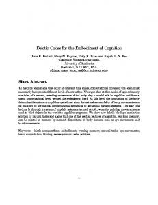
Fig. 1. Graphical notation of the interfaces of cedar. The figure contains two components (‘field 1’ and ‘field 2’) and a looped trigger (large circle).
2
A Software Framework for Dynamic Field Theory
DFT models consist of interconnected dynamical systems, most prominently dynamic neural fields (DNFs), that evolve continuously in time. The connections between DNFs vary in complexity, from simple identity mappings to chains of more complex operations that may include transformations such as mappings between DNFs of different dimensionality. cedar provides a graphical interface to build DFT models from a set of connectable core components. Models can be simulated in real time by numerically approximating the underlying continuous dynamical systems. 2.1
Dynamics and Processing Steps
An architecture in cedar is composed of processing steps. They update their output based on a number of current inputs that originate from other components of the architecture. Processing steps that implement dynamical systems are called dynamics. In addition to the inputs, their updates depend on their inner state. These inputs and outputs are formalized as sets of named input and output slots, whereas the inner states of dynamics use internal slots called buffers. These input and output slots are used to define connections from and to other components of the architecture. Slots of dynamics contain matrices which represent the neural activation fields that are the inner state of the neural dynamics. In general, however, there are no restrictions on the type of data stored in slots. This enables us to work within the same framework when using neural dynamics as when we connect these dynamics to components that are based on non-neural data, for instance, at the interface to hardware devices. Both dynamics and processing steps have adjustable parameters, which can be displayed, manipulated online, and stored as part of the overall architecture. This helps modelers to find suitable operational regimes for the dynamic neural fields. 2.2
Timing
In implementation on a computer-controlled robot or in computer simulation, the time courses of dynamical systems must be numerically approximated by
4
The cedar software framework
iterative, discrete time steps. In cedar , this approximation is based on a solver of differential equations, using the forward Euler method. Although numerically not very efficient, the forward Euler lends itself to working with stochastic dynamics as well as to real-time implementation [7]. Individual components of the dynamics implement their update rule (i.e., the dynamics equation) based on their current state. A special element, the looped trigger (see Fig. 1), is responsible for periodically invoking this update with one of the following user-selectable timing schemes. Fixed time step: The user specifies a fixed duration for the time step, which determines the minimum interval between iterations. If the duration of computation in an iteration step exceeds this fixed time step, the trigger skips an appropriate number of iterations or adapts its step size to the new duration. Real time: Iterations are performed as often as possible and the time between two consecutive iterations is used as the time step. This means that the time step is determined by the amount of time it takes to update the overall architecture. Simulated time: The trigger sends a fixed time step, regardless of how much time passes between iterations. This mode can be used to perform simulations that run faster than real time or to achieve numerical stability when other modes fail to do so. A separate, non-looped triggering mechanism invokes updates of non-dynamic operations along the outgoing connections of dynamic components, thus creating an ordered chain of updates. 2.3
Connections
When different components of an architecture are connected by the user, the underlying framework checks the validity of these connections. They are valid if the type and properties of the connected output match the expectations of the receiving component. Potential semantic flaws result in a warning. Connections are invalid if they cannot be handled by the receiving component. 2.4
Graphical Notation and User Interface
Fig. 1 illustrates how two components, each of which implementing a DNF, are represented graphically. The small circles and diamonds attached to each component represent the input (left), buffer (top), and output (right) slots. Outputs from multiple other components may be connected to the diamond (for DNFs, these inputs are summed up). Input slots drawn in light-gray indicate that the components can be updated even when no input is connected. The green line between the neural fields represents a valid connection of the output of one field to the input of the other field (yellow lines would indicate warnings, red lines errors). The large round circle represents a looped trigger; the light gray lines originating from it indicate which updates it invokes. cedar provides a graphical application (see Fig. 2) that offers tools for designing architectures in a drag-and-drop manner using this graphical notation.
The cedar software framework
5
Fig. 2. Components of the graphical user interface. The pool of all available components is placed on top (A). It contains components available in cedar and the loaded plugins, grouped by theme. Desired components can be dragged onto the architecture canvas (B). Two display modes are demonstrated here: icon-only (left component) and iconand-text (“field 1”). The current state of the neural field—the activation—is plotted in a separate window (C). The parameters of the field can be inspected and altered in the property pane (D).
The ability to plot the data in the slots of components allows for online inspection. A suitable plot class is chosen automatically, but users may also choose other plot classes manually, e.g., for plotting matrices either as images or surface plots. New plot classes can be loaded at runtime via a plug-in structure. Users may also inspect other properties of a component, for instance, the dimensionality and size of matrices. Online manipulation of parameters is accessible in the user interface as well. The user interface provides the designer with feedback. Faulty connections and components that are in an erroneous state are highlighted in different colors. Additional features make the process of designing architectures more comfortable. When connecting components, for instance, all available end-points are highlighted and the validity of the potential connections is shown. 2.5
The DFT Toolbox
cedar provides essential components for DFT architectures, ordered into thematic groups. The group ‘DFT’ includes the core building blocks for architectures. The ‘neural field’ component provides a single-layer neural field of arbitrary dimensionality with lateral interactions [1]. ‘Preshape’ implements a memory trace for neural layers, which adapts to a given input over time, taking into account time scales for build-up and decay. Two processing steps, ‘rate-to-space-code’ and ‘space-to-rate-code’, transform population-based neural dynamics into ratecoded neural activity [14] and vice versa. These mechanisms are used to connect
6
The cedar software framework
Fig. 3. Screenshot of an exemplary architecture created using the graphical user interface of cedar (groupings, e.g., ‘task input’, have been added manually). This DFT-based architecture controls an e-puck robot equipped with a color camera and makes it drive toward objects of specific colors, in this case the red block. The selection decision regarding the target is stabilized over time by a dynamic neural field.
to the motor surface and proprioception. The processing step ‘rate-matrix-tospace-code’ interprets a matrix of rate-coded neurons along a space code metric. All components in the group sources feed sensory input into architectures. cedar currently supports camera devices, video files, and images. Moreover, cedar includes artificially generated inputs, e.g., a homogeneous ‘boost’, a localized ‘Gaussian input’, and ‘noise’. While noise is inherent in physical sensory inputs to an architecture, it is also an important tool during the tuning of an architecture, e.g., to test the stability of a system for various levels of noise. The source ‘net reader’ provides matrices that are sent by another process using a networktransparent protocol. The complementary component, ‘net writer’, is found in the group sinks. The current implementation uses YARP [8] to transfer these matrices between processes and workstations. The group ‘utilities’ offers solutions for connecting components of different dimensionality and granularity [14], for configuring the connection strength via scalar multiplication or arbitrary convolution of outputs, and general mathematical operations such as ‘sum’, ‘component-wise multiplication’, and ‘coordinate transformation’. cedar provides a group ‘image processing’ with basic operations for closing the gap between image sources and population dynamics. It comprises a channel split and a color space conversion. More image processing operations (and other special-interest components) have been implemented in plugins which can be loaded at runtime. This keeps the core of cedar focused on modeling neural architectures with DFT.
3
Case Study
As an illustration, we implement a cognitive architecture in cedar and connect it to an e-puck, a small robot equipped with a differential drive and a color camera.
The cedar software framework
7
The architecture is based on a model that selects a target by a given color cue (see Fig. 3). This paradigm is derived from a more complex phonotaxis robot [3]. The core element of the model is its decision mechanism, a dynamic neural field (DNF). It receives input from the visual sensory system about the location of salient target objects. Additionally, it receives an input that biases its decision toward a target of a specific color. The DNF selects one of the targets, stabilizes that decision against sensory fluctuations, and tracks the location of the target over time. The generated motor output orients the robot so that the selected object is centered in the camera image. We implemented this model in the graphical user interface of cedar , composing the architecture from available elements by drag-and-drop (see Fig. 3) and tuning all parameters online. The resulting architecture consists of four parts: first, the visual preprocessing of the camera image; second, the task input that selects the range of colors the robot is attracted to; third, the DNF, which receives input from both the preprocessing and the task input; and fourth, the connection from the DNF to the robotic hardware. Please note that the architecture works in a closed loop through the environment in which the robot is embedded, even though this is not directly apparent from the figure. The sensory data impacts on the motor commands of the robot and vice versa. The visual preprocessing consists of a sequence of image processing steps. They convert the camera’s RGB-color images to saliency-based activation values which are then input to the DNF. The activation is defined over a twodimensional space spanned by the horizontal viewing angle of the robot and a color metric. High activation values thus represent an object of a certain color at a certain horizontal location. The task input enters the DNF as a ridge of activation along the horizontal viewing angle (see, e.g., [14]) and biases the selection of objects toward a particular color. Once the DNF has formed a peak and thereby selected a target object, that peak controls the robot. The position of the peak along the horizontal axis is translated into rate-coded neural activation that indicates the direction of the colored object relative to the robot’s current orientation. It is directly used as a turning rate of the robot, essentially turning the robot toward the object [3]. By adding a constant forward speed, the robot is able to drive toward the object. When presented with several targets, the robot selects the most salient one of the specified color and successfully drives toward it.
4
Conclusion
In the case study (Section 3), we illustrated cedar with an exemplary architecture derived from a simple cognitive model. The implementation of this model demonstrated how cedar addresses the key requirements on software that we identified in Section 1. Ease of implementation is achieved by using a graphical drag-and-drop interface for the assembly of architectures. This interface can also be used when connecting physical devices such as robots, to cognitive architectures. Architectures can be simulated, inspected, and parameterized in real time,
8
The cedar software framework
enabling us to quickly assess the interdependence of regimes of different DNFs and the embodiment of cognitive architectures. Adding new hardware devices is currently done individually for each new device. In our next major release, we plan to offer a more principled approach that reduces this overhead. We also aim to further enhance the ease-of-use and scalability in future versions. Groups, which enable users to combine a set of components into reusable modules are planned as part of this effort, as are global parameters which can change multiple parameters simultaneously according to user-defined relations.
References 1. Shun-ichi Amari. Dynamics of pattern formation in lateral-inhibition type neural fields. Biological Cybernetics, 27:77–87, 1977. 2. Ulysses Bernardet and Paul FMJ Verschure. iqr: A tool for the construction of multi-level simulations of brain and behaviour. Neuroinformatics, 8(2):113–134, 2010. 3. Estela Bicho, Pierre Mallet, and Gregor Sch¨ oner. Target representation on an autonomous vehicle with low-level sensors. International Journal of Robotics Research, 19(5):424–447, 2000. 4. Andy Clark. An embodied cognitive science? Trends in Cognitive Sciences, 3(9):345–351, 1999. 5. Chris Eliasmith and Charles H Anderson. Neural engineering: Computation, representation, and dynamics in neurobiological systems. MIT Press, 2004. 6. Wolfram Erlhagen and Gregor Sch¨ oner. Dynamic Field Theory of movement preparation. Psychological Review, 109(3):545–72, 2002. 7. Peter E Kloeden and Eckhard Platen. Numerical solution of stochastic differential equations. Springer, 2nd edition, 1999. 8. Giorgio Metta, Paul Fitzpatrick, and Lorenzo Natale. YARP: Yet another robot platform. International Journal on Advanced Robotics Systems, 3(1):43–48, 2006. 9. Mathis Richter, Yulia Sandamirskaya, and Gregor Sch¨ oner. A robotic architecture for action selection and behavioral organization inspired by human cognition. In IEEE/RSJ International Conference on Intelligent Robots and Systems, pages 2457–2464. IEEE Press, 2012. 10. David E Rumelhart and James L McClelland. Parallel Distributed Processing: Explorations in the microstructure of cognition. Volume 1. Foundations. MIT Press, Cambridge, MA, 1986. 11. Gregor Sch¨ oner. Dynamical systems approaches to cognition. In Cambridge Handbook of Computational Cognitive Modeling, pages 101–126. Cambridge University Press, 2008. 12. Anne R Schutte, John P Spencer, and Gregor Sch¨ oner. Testing the Dynamic Field Theory: Working memory for locations becomes more spatially precise over development. Child Development, 74:1393–1417, 2003. 13. Terrence C Stewart, Bryan Tripp, and Chris Eliasmith. Python scripting in the Nengo simulator. Frontiers in Neuroinformatics, 3, 2009. 14. Stephan K U Zibner, Christian Faubel, Ioannis Iossifidis, and Gregor Sch¨ oner. Dynamic Neural Fields as building blocks for a cortex-inspired architecture of robotic scene representation. IEEE Transactions on Autonomous Mental Development, 3(1), 2011.