326
IEEE TRANSACTIONS ON MULTIMEDIA, VOL. 3, NO. 3, SEPTEMBER 2001
A Spatio-Temporal Concealment Technique Using Boundary Matching Algorithm and Mesh-Based Warping (BMA–MBW) Luigi Atzori, Member, IEEE, Francesco G. B. De Natale, Member, IEEE, and Cristina Perra
Abstract—The transmission of block-coded visual information over packet networks introduces fidelity problems in terms of data losses, which result in wrong reconstruction of block sequences at the decoder. Concealment techniques aim at masking the visual effect of these errors, by exploiting either spatial or temporal available information. Both temporal and spatial approaches present drawbacks: the first is in general inefficient in handling complex or fast objects’ motion, while the second is computationally expensive and is not able to recover high-frequency contents and small details. In this paper, a new solution is proposed that combines temporal and spatial approaches. The technique first replaces the lost block with the best matching pattern in a previously decoded frame (BMA), using the border information, and then applies a meshbased warping (MBW) that reduces the artifacts caused by fast movements, rotations or deformations. The first step is achieved by a fast matching algorithm, for a high precision is not needed, while the second step uses an affine transform applied to a deformable mesh structure. Experimental results show that significant improvements can be achieved in comparison with traditional spatial or temporal concealment approaches, in terms of both subjective and objective reconstruction quality. Index Terms—Affine transform, boundary matching algorithm, mesh-based processing, spatial and temporal concealment, video concealment.
I. INTRODUCTION
I
N THE last decade, a great effort has been spent in studying effective solutions for the transmission of digital video over data networks. In particular, packet video is the emerging technology for a wide range of applications and services, including video conferencing and DTV over the Internet. A crucial point for the overall performance of these applications is the quality of the video data delivered to the end user. In this context, standard compression techniques (e.g., MPEGx, H.26x [1]) are usually adopted to reduce the needs in terms of bandwidth, while ensuring acceptable reconstruction quality. Nevertheless, due
Manuscript received November 28, 1999; revised February 28, 2001. The associate editor coordinating the review of this paper and approving it for publication was Dr. Chung-Sheng Li. L. Atzori is with the Department of Electrical and Electronic Engineering, University of Cagliari, 09123 Cagliari, Italy (e-mail:
[email protected]). F. G. B. De Natale is with the Department of Biophysical and Electronic Engineering, University of Trento, 38050 Trento, Italy (e-mail:
[email protected]). C. Perra was with the Department of Electrical and Electronic Engineering, University of Cagliari, 09123 Cagliari, Italy. She is now with Tiscali Communications Company, Cagliari, Italy (e-mail:
[email protected]). Publisher Item Identifier S 1520-9210(01)07789-6.
to the extensive use of predictive and variable length codes, a compressed stream is in general more vulnerable to data losses and transmission errors, which can desynchronize the decoder causing spatial and temporal error propagation. Several methods have been proposed to increase the transmission robustness. Forward error correction schemes (FEC) can be used to protect the most significant parts in the bit-stream. Resilient coding makes possible the stream decoding also in the presence of unreliable transmission: as an example, layered coding ensures a minimum guaranteed level of quality even in critical situations, by partitioning the picture information into several streams with different transmission priorities [2]–[4]. Differently, error concealment techniques aim at masking the visual effects of errors in the decoded data. These techniques typically make use of the correlation with adjacent data (in the spatial or temporal dimension), to extrapolate the missing information. In temporal concealment, a matching area from a previous frame is used to replace the missing area in the damaged one, while in spatial concealment the lost image portion is interpolated from the nearest available data. Techniques based on the estimation of the lost block motion belong to the first category [5], [6]. In particular, boundary-matching criteria are used to minimize the contrast between the replaced blocks and the pixels nearby. As to spatial concealment, in [7] the edges of a large region surrounding the damaged area are exploited with an iterative process in the frequency domain, based on the method of projections onto convex sets. In [8], high-frequency information is recovered by a fuzzy logic reasoning, which provides a modeling of complicated textures and contours. In [9], the missing block is recovered by analyzing the sketch information (contour geometry and relevant gray level variation) in the surroundings blocks and synthesizing the sketch of the missing region, from which the low-frequency content can be easily interpolated. The choice between spatial and temporal approaches is based on the characteristics of both signal and decoder. In particular, temporal recovery typically fails in the presence of scene changes, fast movement, rotation and deformation of objects. Furthermore, it implies a large use of memory in the hardware implementation. Spatial concealment is in general computationally expensive and far less performing in static areas, due to the difficulty in recovering small details and textures, as well as the introduction of tiling effects. In this paper, a new concealment solution is proposed that combines temporal and spatial approaches. The technique uses a temporal replacement of the lost block with the best matching
1520–9210/01$10.00 © 2001 IEEE
ATZORI et al.: SPATIO-TEMPORAL CONCEALMENT TECHNIQUE USING BMA–MBW
pattern in a previously decoded frame, followed by the application of a patch transform aimed at reducing the visible artifacts generated by fast movements, rotations and deformations. The first step is achieved by a fast search algorithm, for a high precision is not required at this stage, while the second step uses a mesh-based transformation to fit the block content with the correctly received surrounding area. The paper is structured as follows. Section II shortly presents the paper background. In Section III, the proposed approach is presented with application to isolated block losses, while in Section IV the algorithm is extended to the case of multiple block losses. Finally, Section V presents the experimental results and in Section VI the conclusions are drawn.
327
selected among a set of candidates extracted from the reference frame and summed with the displaced frame difference (DFD) of the lost block. If also the DFD is unavailable, the one of a spatially adjacent block is used. The selection is performed by minimizing the parameter, according to the following formula:
II. BACKGROUND This section provides a brief survey on the state of the art methodologies that were used as a basis of our work. Temporal concealment techniques are first reviewed, used in the first processing step. Mesh-based motion representation approaches are then reported, which create the basis for the second phase. A. Previous Work in Temporal Error Concealment Temporal error concealment aims at replacing a missing image area with the more likely pattern in a previously decoded frame. Typically, it involves inter-coded frames, which are forward or backward predicted inside a GoP, and makes use of the available motion information in the area surrounding the lost blocks. Notwithstanding, temporal information can also be exploited in the restoration of I-frames, where motion vectors can be directly extracted at the decoder at the expense of a higher computation. To this aim, local motion can be estimated at the decoder by using modified versions of classical block matching algorithm: for instance, available image data at the boundaries of the damaged area can be matched with the corresponding areas in a previously decoded reference frame using a full-search algorithm [10]. Of course, this estimation is not effective in the case of scene changes or fast movement, and suffers from the distortion present in the compressed domain. In the simplest approaches, the lost area is replaced with a corresponding area in a reference frame, with no additional post-processing. The problem is then to search the best motion vector for the damaged area, based on the motion of surrounding blocks. In [11], some simple solutions are proposed, based on replacing the lost motion vector by — a zero-motion vector, for areas with slow or null motion; — the motion vector of the block in the same position in the previous frame; — the average of the motion vectors of spatially adjacent blocks; — the median of the motion vectors of spatially adjacent blocks. In [5], the motion vector is obtained by minimizing a ) measure between the replaced macboundary matching ( parameter is the square roblock and its surroundings. The difference between the external boundary of the lost block and the internal boundary of the replacing block. The last is
(1) where coordinates of the top-left pixel of the lost block; pixels values of the damaged frame; pixel values of the reference frame to which the DFD values were added; possible motion vectors, taken from a predefined set including the null vector, the vector of the corresponding block in the previous frame, and those of the adjacent blocks. Each of the four sums represents the boundary matching on a block side. The algorithm is fast and gives good results if the damaged area involves only translation movements. Similar solutions have been proposed to find the motion vector that provides the best overlapping between the external boundary of the lost block in the current frame and the corresponding areas in the reference frame. In [12], the one-pixel wide bands on the top and left side of the lost area are used to perform the matching, being the only available in on-line concealment. In [13], the pattern used is two-pixels wide and includes the bottom side too. All of these methods have a common drawback, represented by the introduction of blocking artifacts in the recovered area. This problem arises from the impossibility of compensating the motion of the damaged area in several recurrent situations, such as: rotational movements, scale and deformation of objects, occluded background appearing, incoherent motion of different objects inside the block. In these cases, a simple compensation based on block translation will produce fragmentation of edges, objects’ deformation, and other artifacts. In [14], a possible solution to this problem is proposed, based on the combination of a boundary-matching algorithm with an interpolation of the surrounding motion information. For each pixel, a weighted mean of the four connected motion vectors is computed, taking into account the distance of the pixel from the relevant block sides. The resulting motion field is different for each pixel, and is complemented with the boundary matching information to obtain the final motion vector. Also in [6] a pixel-wide motion compensation is proposed, where the lost block is divided into
328
four overlapped sub-blocks, independently recovered by a position-weighted average of three motion vectors: one is achieved by a side matching algorithm (similar to boundary matching), while the other two are the motion vectors of the up and left adjacent blocks. In [10], a weighted boundary matching algorithm is described, where the boundary matching error expression of (1) is modified introducing appropriate weights for each of the error measures relevant to the four boundary sides. Such weights are proportional to the local spatial correlation computed at the reference block boundaries.03mm
IEEE TRANSACTIONS ON MULTIMEDIA, VOL. 3, NO. 3, SEPTEMBER 2001
Fig. 1. Triangular mesh-based motion representation for a polygonal object: the mapping of the texture inside each element is made by affine transform.
B. Two-Dimensional Mesh-Based Motion Representation Motion compensation based on simple block translation has proven to be an effective solution if accompanied by some prediction error encoding. This model is currently adopted by many video coding standards. Nonetheless, more complex and effective solutions have been proposed aimed at representing a generalized block motion. Affine, bilinear, and perspective mappings are the most interesting examples. In addition to translation, they permit to model rotation, scaling, reflection, and shrinking, representing the projection of a three-dimensional rigid motion of a planar patch onto the image plane. In this case, the tiling effect due to block-based motion compensation is avoided by introducing a two-dimensional mesh structure that divides the image into polygonal patches [15]–[18]. The compensated frame is then achieved by displacing the vertexes (node points) of the mesh, which control the deformation of each polygonal element. The texture contained in each polygon of the reference frame is then warped onto the current frame, according to the grid deformation. The main difference between these techniques and block-based modeling is in the fact that there is not any superposition of patches in the reference or in the current frames, thus preventing the introduction of blocking artifacts (see Fig. 1). On the other side, a drawback of mesh models is that they implicitly blend the motion of adjacent image areas. For this reason they are able to represent mildly deformable but spatially continuous motion fields, but cannot handle discontinuities in the motion field (e.g., they can be successfully used to model facial expressions). As to the implementation details, the estimation of the mesh deformation is achieved by searching the points of the current frame that best match the grid nodes of the reference frame. The tracking of such nodal points can be performed in several ways: the simplest approach is to use blocks centered in the node positions and search for the motion vectors using a gradientbased technique or a block matching. In forward mesh motion estimation, one sets up a mesh in a previous reference image and searches for the best matching locations of the node points in the current image. There are two options: 1) set up the mesh only in the first reference image and continue to deform it in successive images based on the node motion vectors; and 2) set up a nonuniform mesh on the previously reconstructed frame by using the same algorithm at the encoder and the decoder. In the first method, image features are tracked through the entire sequence (forward tracking mesh). The initial mesh may be regular, thus not implying the overhead of transmitting the mesh geometry, or can be adapted to
Fig. 2. Tasks involved in the proposed concealment procedure: BMA concealing of the missing macroblock, design of the transform mesh to apply to the macroblock, estimation of the node points motion, and mesh affine transform.
the image (content-based mesh), in which case the initial mesh geometry should be transmitted. In the second case, the mesh is rebuilt at every frame, but there is no transmission overhead. Typical polygons used for mesh-based motion compensation are triangles and quadrangles, while most used mesh texture mapping techniques make use of the affine transform, to map spatial coordinates at time into spatial coordinates at time . III. MESH-BASED WARPING (MBW) As discussed above, most temporal concealment methods simply replace the lost area with a patch taken from a previously decoded frame that minimizes a given error measure. Similarity measures usually involve the external boundary of the area to be recovered, and motion is modeled by a rigid translation. Whenever the real motion does not conform to uniform translation (e.g., object rotation or zooming, objects with different motion inside a block, occluded background), these techniques usually fail, introducing annoying effects as tiling, edge discontinuities and other artifacts that impair the concealment performance. To avoid these drawbacks, the proposed technique performs the concealment in two steps: first, the missing blocks are temporally replaced using a classical approach know as boundary matching algorithm (BMA), in order to consider the pure translation, and second, the internal texture of each block is warped by a mesh-based affine transform, in order to comply with nontranslation movements. Both operations involve the external boundary of the lost block, and aim at achieving the best fitting of the patch with the correctly decoded surrounding area. It has to be pointed out that often the required patch deformation cannot be obtained by an unique affine transform applied
ATZORI et al.: SPATIO-TEMPORAL CONCEALMENT TECHNIQUE USING BMA–MBW
329
putation, it is not performed if not needed: the temporal activity of the damaged area is then estimated through (2) (2)
Fig. 3. Asymmetric triangular mesh applied to a lost macroblock area: the control nodes (C ) and the internal nodes (P ) are represented by black and gray points, respectively.
Fig. 4. Displacement prediction for the control point C : L is the length of the node vector, while W is the searching window size.
Fig. 5. Transform of the triangular element nearby the block vertexes. (a) In order to overcome the problem of mapping a triangular element to a quadrangular element, (b) the new control point A is introduced.
to the whole block, such as a combination of rotation, scaling and shearing of the block. In fact, this solution cannot take into account heterogeneous motion inside a block, which is quite common for large block sizes used in current standards, and almost sure in multiple block losses. Then, it is necessary to perform a tessellation of the outset block into more patches, to which distinct affine transforms are applied, similarly to what is done in mesh-based motion compensation techniques described in Section II-B. This tessellation can be conveniently achieved by superimposing a mesh to the patch and deforming the texture according to some node displacement criterion, based on the available surrounding information. In Fig. 2 a scheme of the proposed concealment method is drawn. Since the mesh-based deformation requires extra com-
where is the number of available surrounding blocks and is the th motion vector, and if it does not exceed a given threshold only BMA is used. When needed, the matching between internal/external boundary of the BMA replaced block is performed, in order to estimate the motion of the node points located in the perimeter, which is then propagated to the internal node points by an appropriate interpolation scheme. Once the grid displacement is obtained, the affine transform is easily applied to achieve the concealed block. It has to be noted that the choice of the mesh shape and density is not a trivial problem, for a more complex structure could allow a better representation of composite deformations, increasing at the same time the computational load of the second step. As already mentioned, a transmission error usually involves the loss of more consecutive blocks, due to synchronization problems in the decoder. Therefore, an effective concealment method must be able to support multiple block losses. For the sake of simplicity, the main problems relevant to the method implementation are discussed in the following of this section with reference to an isolated block loss. Multiple block losses are then addressed in the Section IV. A. Definition of the Mesh Structure In image processing applications, adaptive meshes are often used to partition the image plane in a set of contiguous regions with uniform characteristics. This is usually accomplished by suitably distributing the nodal points of the mesh with a density proportional to the local image activity. In the case of motion analysis, a larger number of nodes are used in the areas characterized by a fast or complex movement. Sometimes, it is preferable to start with a regular mesh, and progressively deform it: as an example, in [18], the nodes are shaped around the image edges, whose positions are heuristically found, while in [17], the mesh is modeled by means of an energy minimization function, taking into account the patch smoothness, the gradient at the node positions, and the mesh regularity. In [19], the DFD is exploited in order to place the node points in the most important motion activity areas. Although these adaptive strategies are workable in video coding, being no subject to stringent real-time constraints, they are computationally too intensive for real-time video concealment applications. In order to achieve a sufficient accuracy with a fixed mesh it is therefore important to use a sufficiently thick mesh, to overcome the limitations of rigid structure. Another important aspect in image concealment is that the available information is concentrated in the perimeter of the lost area. It is therefore convenient to place most part of the grid control points in that region, where the displacement information can be more accurately calculated. The specific mesh structure depends upon the dimension and geometry of the area to be recovered. Fig. 3 shows the mesh used for a single MPEG
330
IEEE TRANSACTIONS ON MULTIMEDIA, VOL. 3, NO. 3, SEPTEMBER 2001
Fig. 6.
Affine mapping between irregular elements (D
! O) is made easier by two transforms with a regular element (master element, M ).
Fig. 7. Displacement estimation for control nodes shared by two adjacent damaged macroblocks: (a) the deformation of region in the second macroblock is implicitly fixed by the motion estimation applied to the first macroblock; and (b) additional control nodes are introduced inside region (points C ; C ; C ), and are displaced accordingly.
macroblock ( pixels): 12 nodal points are uniformly distributed along the perimeter (control nodes), while four nodes are placed in the inner region (internal nodes).
Fig. 4 provides an example of the matching procedure applied to a control node located in the north side of the damaged macroblock. As to the computation, the mathematical expression of the matching criterion is the following:
B. Control Nodes Displacement Estimation After the temporal replacement of the lost block through the BMA, the above-defined mesh is superimposed to the block, to achieve the spatial adaptation of the recovered area. The motion of the control node points is first estimated by matching the image features along the internal block perimeter with the corresponding features along the external one. A simple and fast solution to achieve this task is to seek the correspondences between the control points and the external perimeter. To this purpose, for each control point a vector of pixels belonging to the internal block boundary and centered on the node itself is set (node vector), and used to find the best matching displacement. An error measure is defined as the mean square difference between the node vector and a corresponding displaced vector on the external boundary (reference vector). The reference vectors are circularly moved by shifting the pixels along the external boundary. The position of the reference vector that provides the least MSE with the node vector gives the node displacement along the internal boundary.
where (3) represents the image gray level at pixel , and are the coordinates of the control node . The node is not moved , otherwise it is displaced by a vector if , 0). The threshold has been introduced in order to ( avoid unwanted mesh deformations due to noise. and the Two important parameters are the vector size , that is the maximum allowed node displacesearch window makes the node matching operation ment. A low value of faster and more local, while bringing the procedure less robust to noise. Large values of the search window dimension allow managing heavy block deformations, while increasing the comand were experputational load. Appropriate values for imentally found to be 5 and 4, respectively.
ATZORI et al.: SPATIO-TEMPORAL CONCEALMENT TECHNIQUE USING BMA–MBW
331
Fig. 8. Results on a synthetic test sequence with missing isolated macroblocks: (a) original reference frame; (b) original current frame; (c) damaged frame (five lost macroblocks); (d) BMA reconstruction,; and (e) proposed method.
Fig. 9. Subjective video quality comparison for the synthetic sequence of Fig. 8: (a)–(e) magnified frame details after BMA concealing and (f)–(l) proposed method.
A particular situation happens when a block vertex is displaced. In this case, a triangular mesh element becomes a quadrangle, thus requiring a more complex transformation [see Fig. 5(a)]. To solve this problem, an additional node is in Fig. 5(b)], thus dividing the relevant introduced [point mesh element into two triangular elements. The position of the new point is determined such that the ratio of the length and is equal in both the of the two segments original and deformed mesh; furthermore, it does not requires
any displacement estimation, for it should be positioned at the vertex of the deformed block. C. Displacement of Internal Nodes The displacement of internal nodes is obtained in the proposed scheme by a direct interpolation of the control nodes. As a matter of fact, it was not judged convenient to apply a motion estimation based on border information also to internal nodes, due to two main reasons: first, the distance of these points from
332
IEEE TRANSACTIONS ON MULTIMEDIA, VOL. 3, NO. 3, SEPTEMBER 2001
Fig. 10. Results on the “rai” test sequence with missing macroblocks’ rows (21 consecutive macroblocks per row): (a) original; (b) damaged with a 28% macroblock loss; (c) BMA reconstruction; and (d) proposed method.
Fig. 11.
Subjective video quality comparison for the “rai” sequence: (a)–(c) magnified frame details after BMA concealing and (d)–(f) proposed method.
the block boundary is higher, and therefore their correlation is lower; second, the computational complexity can be highly reduced by decreasing the number of matching operations. The
displacement of internal nodes is then computed by averaging the displacement vectors of the neighboring nodes, weighted by the inverse of their distance. The mathematical expression used
ATZORI et al.: SPATIO-TEMPORAL CONCEALMENT TECHNIQUE USING BMA–MBW
333
Fig. 12. Results on “table tennis” test sequence with losses of isolated macroblocks and short sequences of consecutive macroblocks: (a) original; (b) damaged with a 8% macroblock loss; (c) BMA reconstruction; and (d) proposed method.
to compute the propagated motion ( is the following: node
) of the internal
irregular element (target). The mapping from the master (coordinates ) to the target (coordinates ) is expressed as follows: (5)
(4)
is the distance of the internal node from the conwhere , and is the number of control node points used trol node in the interpolation.
where the six parameters are determined by the position of the ) nodes in the target (
(6) Instead, the inverse mapping is obtained through the following expression:
D. Block Texture Warping The mesh deformation so far achieved also determines the mapping of the internal texture. In [20], a detailed mathematical solution for the affine transform applied to quadrilateral and triangular mesh is presented. The affine transform from a generic polygonal element to another one can be simplified by transforming the starting element into a regular one, and then transforming the regular element into the target one (see Fig. 6). In such a way, the mapping procedure is split into two easier operations, each one between a regular element (master), and an
(7) where
is the Jacobian for the forward mapping: (8)
334
IEEE TRANSACTIONS ON MULTIMEDIA, VOL. 3, NO. 3, SEPTEMBER 2001
Fig. 13. Subjective video quality comparison for the “rai” sequence: (a)–(d) magnified frame details after BMA concealing and (e)–(h) proposed method concealing.
TABLE I CONCEALMENT PARAMETERS’ VALUES USED DURING THE RECOVERY OF THE 60 DAMAGED FRAME OF THE “TABLE TENNIS” SEQUENCE (RESULTS SHOWN IN FIGS. 12 AND 13)
On this basis, the warping of each block element is performed by applying in sequence an inverse and a forward mapping (9) and represent the pixel coordinates of the where starting and deformed element, respectively (see Fig. 6). IV. RECOVERY
SEQUENCE OF CONSECUTIVE MACROBLOCKS
OF A
The method so far described was targeted to the recovery of isolated block losses, where the surrounding information is supposed to be completely available. Nevertheless, the hypothesis of isolated block losses is often not realistic in image and video coding, due to the intensive use of VLC and predictive codes in current standards, which may cause decoder de-synchronization and error propagation. The recovery of a block sequences is then a more practical matter. The proposed method can be quite efficiently modified to handle multiple block losses. The first step is again to temporally replace each block with the boundary matching algorithm:
the only difference at this stage is that the boundary matching should be performed on a different set of block sides, depending on the block position within the missing sequence. In particular, three sides are used for the first lost block (N, W, S), and only two for the following ones (N, S). If the last block of the lost sequence does not fall at the end of the row, it is possible to also use three sides for it (N, E, S). The second step is more complex. In fact, when applying the mesh-based warping (MBW) procedure to the facing sides of two consecutive blocks, it is important to consider that some control points are shared between them. Since blocks are processed in sequential order, already processed blocks impose some constraints on the displacement of shared control points. Consequently, the overall reconstruction achieved in this way is not satisfactory. To handle this problem, warping is performed through the following steps. Step 1) Reconstruct the entire sequence of damaged macroblocks using BMA, and superimpose the mesh represented in Fig. 3 to each block. Step 2) Estimate the displacement of control nodes belonging to the first block by using the same algorithm used for isolated lost macroblocks. Step 3) If the following block belongs to the damaged sequence, consider the control points located on the right side of the mesh [points in Fig. 7(a)]. According to the results of the displacement estimation procedure, a subset of these points ( ) matches some image patterns located on the perimeter of the second block [region in Fig. 7(a)]. Define a new set of control nodes ( ) in region of the second block, corresponding to the matching is locations of the points in . In the example, , and made up of the three points of the three points . Then, compute the refined displacement vectors for shared control nodes by averaging the original coordinates of and [see Fig. 7(b)], and matching pairs in
ATZORI et al.: SPATIO-TEMPORAL CONCEALMENT TECHNIQUE USING BMA–MBW
335
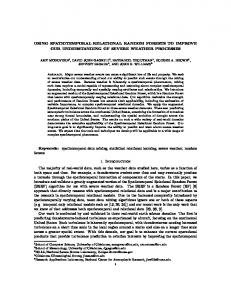
Fig. 14. PSNR values for the first 60 frames of the test sequence “table tennis.” The sequence is affected by data losses with a 10.57% of macroblock missing, and recovered with three different concealment techniques: zero motion temporal replacement, BMA algorithm, and mesh-based block transform. TABLE II PSNR MEAN VALUES COMPARISON FOR THE DIFFERENT TECHNIQUES
warp the first block with the resulting set of displaced nodes. Step 4) Estimate the node displacements for the second that are displaced block, except for those in according to the operation in point 2. Step 5) Again, if the following block belongs to the damaged sequence apply the procedure described in point 2 to refine shared nodes on the right side; then, warp the second block. Step 6) Repeat Steps 3 and 4 on the following blocks, until the end of the damaged sequence or the end of the slice. This procedure ensures an unbiased displacement of shared control nodes and a smooth transition between adjacent warped blocks. V. EXPERIMENTAL RESULTS The proposed method was tested on several video sequences, characterized by heterogeneous spatial and temporal activities. This section presents the results relevant to three test sequences: a synthetic one, specifically generated in order to provide better evidence of the improvement introduced by MBW as compared to classical BMA, and two standard video clips, “rai” and “table and pixels, respectively. Data losses tennis,” were simulated by taking into account different damage configpels), multiple urations: isolated macroblock losses ( macroblock losses, and loss of entire slices. Furthermore, the concealment procedure was applied by using reference frames with different temporal distance from the damaged one (up to
three frames before or after). This corresponds to the recovery of a B-frame coming immediately after a P-frame or after some other B-frames, or to the recovery of a P-frame in a typical GOP configuration. As to the synthetic test set, it was obtained by applying a mix of roto-translations and scale factors to some geometrical objects in a uniform background [original reference and current frames in Fig. 8(a) and (b)]. In this case, the damaged frame was simply achieved by simulating the complete loss of some sparse macroblocks located in critical points [Fig. 8(c)]. This example allows appreciating the inability of BMA to deal complex object movements, except for pure translations [Fig. 8(d)], and the higher performance achieved by MBW [Fig. 8(e)]. Of course, if the missing part of an object was occluded in the reference frame (e.g., the top corner of the white polygonal on the left) MBW cannot achieve a correct reconstruction, but it is able to provide a smooth approximation of the missing area. The magnified details of the concealed macroblocks are proposed in Fig. 9. Figs. 10(a) and 12(a) present one original frame for the two natural test sequences. The damaged frame in Fig. 10(b) represents a very common configuration. In particular, it was assumed that all the macroblocks involved in a packet loss and the following ones until the end of the slice are lost, due to synchronization problems at the decoder. This is a decoding mechanism encountered in most of video standards. Fig. 10(c) and (d) show the results obtained by a simple BMA, as compared to the proposed BMA-MBW. In this example, the previous frame was used as a reference frame. From this example it is possible to observe that some parts of the damaged frame, characterized by a low temporal activity, are adequately recovered by BMA without any additional processing. For these regions, the prediction of the local temporal activity [(2)] avoids the application of MBW, which would increase the computation without significant quality improvement. On the contrary, the regions encompassing the people heads present a notable motion, thus producing annoying blocking artifacts in the simple translationbased model. Here, MBW introduces notable quality betterment, as shown in the comparative details of Fig. 11(a)–(f). Some artifacts still remain, due to the lack of information in the
336
IEEE TRANSACTIONS ON MULTIMEDIA, VOL. 3, NO. 3, SEPTEMBER 2001
Fig. 15. Blocking distortion measure (B ) for the first 60 frames of the test sequence “table tennis.” The sequence is affected by data losses with a 10.57% of macroblock missing, and recovered with three different concealment techniques: zero motion temporal replacement, BMA algorithm, and mesh-based block transform.
temporally replaced block [e.g., the geometrical deformation of the left head in Fig. 11(b)]. Fig. 12(b) show the effects of packet losses in an error resilient coding scheme, where block interleaving [2] or automatic block decoding synchronization [21] is used. In these situations, a data loss may involve isolated macroblocks or short macroblock sequences, concerned with erroneous data. In our tests, the losses were randomly generated over the entire image. Fig. 12(c) and (d) shows the results after applying the BMA and the proposed method, respectively. Furthermore, magnified parts of these images are displayed in Fig. 13, in order to allow a better perceptive quality comparison. From a visual examination it is possible to note that the proposed method provides notable improvements in image areas containing objects with regular geometrical structures and well-defined edges, due to two reasons: first, a better rendering of geometrical structures has a high impact on the human perception of the visual quality; second, the control point displacement prediction is much easier in the presence of well-defined transitions. Video quality improvement is even more visible examining the video sequence rather than the still picture, due to the contrast between the damaged area and that of the subsequent correctly decoded frame. A quantitative evaluation of the concealment results is provided by the PSNR measure, which was computed for a recovered sequence of 60 frames belonging to the “table tennis” sequence. The effects of data losses were simulated by generating randomly distributed block losses with a probability of 10 , and propagating the loss up to the end of the macroblock’ row, bringing the macroblock loss percentage to 10.57%. In order to simulate the loss in a MPEG-like coded sequence (GOP size of 12 and P-frame coded every three frames), the reference frame was alternatively chosen as the previous one, the following one and the frame three temporal shots before. This corresponds to the recovery of a B-frame from the previous I-frame, a B-frame from the successive P-frame, and a P-frame from the past I- or P-frame. Temporal propagation of the errors was not considered
for the sake of simplicity. The value of adopted concealment parameters is displayed in Table I. Fig. 14 shows the PSNR of the sequence concealed with the proposed approach, as compared to other two common methods used in MPEG decoders: replacement of the lost macroblocks with those of the reference frame at the same position zero motion temporal replacement (ZMTR) and BMA. The average PSNR values are also presented in Table II, proving a quantitative improvement of about 1.2 dB with respect to simple BMA and over 5 dB with respect to ZMTR. Obviously, the PSNR does not give a comprehensive measure of the visual quality, which is mainly influenced by other factors, such as the presence of visible artifacts, tiling effect, etc. In order to have an additional quantitative performance evaluation, the following blocking distortion measure was used [22]: where (10) This expression provides an estimation of the tiling present on the image, by measuring the image smoothness on the border of the concealed area (conc) and on the border of the same area in the original image (or). The pixels located in this area define represents the gray level of the set . In this expression, , and provides the image value of the frame pixel in the direction orthogonal to the block the pixel adjacent to border and belonging to the external area. Namely, the smoothness of the concealed image is compared with the one of the gives values close original image, and normalized with it. to zero for undamaged images, and increases with the blocking distortion. curves corresponding to the PSNR Fig. 15 shows the curves of Fig. 14. It is evident that the proposed technique is values signifable to reduce the blocking, providing average icantly lower than BMA and ZMTR, as also shown by Table III. Contrarily to smooth interpolators, this result is achieved by
ATZORI et al.: SPATIO-TEMPORAL CONCEALMENT TECHNIQUE USING BMA–MBW
B
337
TABLE III MEAN VALUES COMPARISON FOR THE DIFFERENT TECHNIQUES
BMA–MBW without introducing any low-pass effect. Another important point about Table III is that it demonstrates how BMA performance rapidly degrades if the reference frame is not immediately adjacent to the damaged one, while BMA–MBW is far less sensitive to the temporal location of the reference frame. A possible malfunctioning of MBW can happen when the matching of control points fails in the warping procedure, thus generating an incorrect mapping of the relevant image areas. This problem may potentially occur at very high compression factors, where the severe distortion introduced in the current and reference frames can generate spurious peaks in the correlation function used for node matching [see (3)]. Experimental evidence demonstrated that this problem does not yield significant effects at low-medium compression factors, where distortion level is reasonably low as compared to signal level. This is a realistic assumption for most part of MPEG-based applications, to which the method is targeted. Further investigations are being conducted for what concerns the application of MBW to very low bitrate video coders. Finally, the limited amount of additional computation introduced by MBW brings the method applicable in real time. In fact, the affine transformation can be performed with a few integer operations, while the estimate of control point displacement just requires light computation, being applied to short onedimensional vectors in restricted search areas.
VI. CONCLUSION A new error concealment technique was presented, aimed at masking the loss of visual information due to erroneous transmission of coded digital video over unreliable networks. The technique is based onto two steps: preliminary replacement of missing blocks by a boundary matching criterion (BMA), and warping of the replaced blocks by using an affine transform applied to a deformable mesh (MBW). The mesh deformation is achieved by estimating the displacement of a set of control points, and works in the spatial domain. MBW allows therefore
compensating nontranslation motions disregarded by simple BMA model. Experimental tests demonstrated that the proposed approach is able to significantly reduce the artifacts that characterize other temporal concealment techniques, increasing both the subjective quality of the concealed image and most used objective quality parameters. The moderate increase of the computational complexity with respect to plain BMA does not preclude the real-time implementation of the technique, which just requires simple integer computation. REFERENCES [1] J. L. Mitchell, W. B. Pennebaker, C. E. Fogg, and D. J. LeGall, MPEG Video Compression Standard. London, U.K.: Chapman & Hall, 1997. [2] I.-W. Tsai and C.-L. Huang, “Hybrid cell loss concealment methods for MPEG-II based packet video,” Signal Process. Image Commun., vol. 9, no. 2, pp. 99–124, Jan. 1997. [3] R. Aravind, M. R. Civanlar, and A. R. Reibman, “Packet loss resilience of MPEG-2 scalable video coding algorithms,” IEEE Trans. Circuits Syst. Video Technol., vol. 6, no. 5, pp. 426–435, Oct. 1996. [4] L. H. Kieu and K. N. Ngan, “Cell-loss concealment techniques for layered video codecs in an ATM network,” IEEE Trans. Image Processing, vol. 3, no. 5, pp. 666–677, Sept. 1994. [5] W.-M. Lam, A. R. Reibman, and B. Liu, “Recovery of lost or erroneously received motion vectors,” in Proc. ICASSP, vol. 5, 1993, pp. 417–420. [6] M. J. Chen, L. G. Chen, and R. M. Weng, “Error concealment of lost motion vectors with overlapped motion compensation,” IEEE Trans. Circuits Syst. Video Technol., vol. 7, no. 3, pp. 560–563, June 1997. [7] H. Sun and W. Kwok, “Concealment of damaged block transform coded images using projections onto convex sets,” IEEE Trans. Image Processing, vol. 4, no. 4, pp. 470–477, Apr. 1995. [8] X. Lee, Y.-Q. Zhang, and A. Leon-Garcia, “Information loss recovery for block-based image coding techniques—A fuzzy logic approach,” IEEE Trans. Image Processing, vol. 4, no. 3, pp. 259–273, Mar. 1995. [9] L. Atzori and F. G. B. De Natale, “Error concealment in video transmission over packet networks by a sketch-based approach,” Signal Process. Image Commun., vol. 15, no. 1/2, pp. 57–76, Sept. 1999. [10] E. T. Kim, S.-J. Choi, and H.-M. Kim, “Weighted boundary matching algorithm for error concealment in the MPEG-2 video bit stream,” Signal Process., vol. 73, pp. 291–295, Mar. 1999. [11] H. Sun, J. W. Zdepski, W. Kwok, and D. Raychaudhuri, “Error concealment algorithms for robust decoding of MPEG compressed video,” Signal Process. Image Commun., vol. 10, no. 4, pp. 249–268, Sept. 1997. [12] M.-C. Hong, H. Schwab, L. P. Kondi, and A. K. Katsaggelos, “Error concealment algorithms for compressed video,” Signal Process. Image Commun., vol. 14, no. 6–8, pp. 473–492, May 1999.
338
IEEE TRANSACTIONS ON MULTIMEDIA, VOL. 3, NO. 3, SEPTEMBER 2001
[13] J. F. Arnold, M. R. Frater, and J. Zhang, “Error resilience in the MPEG-2 video coding standard for cell based networks—A review,” Signal Process. Image Commun., vol. 14, no. 6–8, pp. 607–634, May 1999. [14] M. Al-Mualla, N. Canagarajah, and D. R. Bull, “Temporal error concealment using motion field interpolation,” IEE Electron. Lett., vol. 35, no. 3, pp. 215–217, Feb. 1999. [15] A. M. Tekalp, P. van Beek, C. Toklu, and B. Günsel, “Two-dimensional mesh-based visual-object representation for interactive synthetic/natural digital video,” Proc. IEEE, vol. 86, no. 6, pp. 1029–1051, June 1998. [16] Y. Nakaya and H. Harashima, “Motion compensation based on spatial transformations,” IEEE Trans. Circuits Syst. Video Technol., vol. 4, pp. 339–356, June 1994. [17] Y. Wang and O. Lee, “Active mesh—A feature seeking and tracking image sequence representation scheme,” IEEE Trans. Image Processing, vol. 3, no. 5, pp. 610–624, Sept. 1994. [18] J. Nieweglowski, T. G. Campbell, and P. Haavisto, “A novel video coding scheme based on temporal prediction using digital image warping,” IEEE Trans. Consumer Electron., vol. 39, pp. 141–150, Aug. 1993. [19] Y. Altunbasak and A. M. Tekalp, “Occlusion-adaptive, content-based mesh design and forward tracking,” IEEE Trans. Image Processing, vol. 6, no. 9, pp. 1270–1280, Sept. 1997. [20] Y. Wang and O. Lee, “Use of two-dimensional deformable mesh structures for video coding: Part I—The synthesis problem: Mesh-based function approximation and mapping,” IEEE Trans. Circuits Syst. Video Technol., vol. 6, no. 6, pp. 636–646, Dec. 1996. [21] D. Redmill and N. G. Kingsbury, “The EREC: An error-resilient technique for coding variable-length blocks of data,” IEEE Trans. Image Processing, vol. 5, no. 4, pp. 565–574, Apr. 1996. [22] S.-C. Hsia, J.-F. Yang, and B.-D. Liu, “Efficient postprocessor for blocky effect removal based on transform characteristics,” IEEE Trans. Circuit Syst. Video Technol., vol. 7, no. 6, pp. 924–929, Dec. 1997.
Francesco G. B. De Natale (M’97) received the Laurea degree in electronic engineering in 1990, and the Ph.D. degree in telecommunications in 1994, both from the University of Genoa, Italy. In 1990, he joined the Signal Processing and Telecommunications Group of the Department of Biophysical and Electronic Engineering, University of Genoa. In 1995 and 1996, he was Visiting Professor at the University of Trento, Italy, and successively Assistant Professor at the University of Cagliari, Italy. At present, he is Associate Professor of Telecommunications at the University of Trento, where he coordinates the didactic activities of the Laurea Course in telecommunications engineering. His research interests are focused on image and signal processing, with particular attention to multimedia data compression, processing, and transmission. In this context, he leads the research activities of the Multimedia Communications Lab at the University of Trento. Dr. De Natale is a Member of AEI. He is the representative for the University of Trento within the Italian Group of Telecommunications and Information Theory (GTTI), and is part of the Management Board of the National Inter-University Consortium of Telecommunications (CNIT). He was appointed evaluator by the EU Commission for some ESPRIT-Programme projects and acts as a referee in several international journals. In 1997, he received the IEEE Chester-Sall Best Paper Award for a scientific publication in the Transactions on Consumer Electronics.
Luigi Atzori (S’97–M’99) was born in Cagliari, Italy, in 1971. He received the Ing. Laurea degree in electronic engineering in 1996 and the Ph.D. degree in 1999, both from the University of Cagliari. In 1994, he spent several months as a Visiting Student at the Technical University, Braunschweig, Germany. At present, he is Assistant Professor in Telecommunications in the Department of Electrical and Electronic Engineering, University of Cagliari. His main fields of interest concern signal processing, with particular attention to error recovery, video post-processing, and image segmentation.
Cristina Perra was born in Cagliari, Italy, in 1971. She received the Laurea degree in electronic engineering in 1997, and the Ph.D. degree in telecommunications for remote sensing in 2000, both from the University of Cagliari. From 1997 to 2001, she cooperated with the Telecommunications Group at the Department of Electrical and Electronic Engineering of the University of Cagliari. At present, she is with Tiscali Communications Company, Cagliari, Italy. Her research interests include image and video processing and transmission, and RS image compression and classification.