The advent of the optical fiber, with its theoretically unlimited bandwidth, ... demand of bandwidth imposed by both new applications and services, and an ...
A Survey of Multicasting Protocols For Broadcast-and-Select Single-Hop Networks 1 Ashraf M. Hamad and Ahmed E. Kamal2 Department of Electrical and Computer Engineering Iowa State University Ames, IA 50011-3060 U.S.A. E-mail: {ashraf, kamal}@iastate.edu
Abstract Multicast communication in single -hop broadcast-and-select Wavelength Division Multiplexing (WDM) networks has received considerable attention from researchers. This paper presents a comprehensive survey of the multicast scheduling techniques in this environment. It considers different challenges that are faced in the design of multicasting techniques, and presents a classification of such schemes. A survey of the specific techniques is then presented, and a comparison is drawn between such techniques. Keywords : Multicast, Single-Hop, Broadcast-and-Select, WDM, Scheduled/Unscheduled transmission, MAC protocols.
1. Introduction The advent of the optical fiber, with its theoretically unlimited bandwidth, presented a solution to the increasing demand of bandwidth imposed by both new applications and services, and an exponentially increasing number of users and the traffic generated by those users. At the same time, it served as an impetus for the development of new bandwidth-intensive applications. Communication networks and their interconnections now have the physical layer infrastructure to provide a high quality of service (QoS) in terms of bandwidth guarantees, which also reflects on lower delay and packet loss, for a large number of users. However, this tremendous bandwidth was not fully utilized by a straightforward employment of state-of-the-art transceivers. The reason is mainly the speed mismatch between the fiber’s bandwidth and the physical limitations on the speed of the electronic s. This problem is known as the electronic bottleneck problem [1], and it is better understood if one compares the fiber's bandwidth of 50 THz to the electronics maximum transmission rate of 10-40 Gb/s, depending on the technology. The Wavelength Division Multiplexing (WDM) [2] technique was developed as a viable method to exploit the fiber’s bandwidth. In a nutshell, WDM allows the simultaneous transmission on several optical frequencies on the same fiber. One class of service, which can capitalize on these advances in networks, is the class of multicast or multi-point service. It is expected that a significant portion of the traffic in future high-speed networks will be of the multicast nature [3]. As such, the problem of multicast communication support has been extensively treated in the literature. Many excellent and comprehensive survey papers and monographs exist which treat the various aspects of multicasting at large [4][5].
1 2
This work is supported in part by the National Science Foundation under grant ANI-0087746 Corresponding author.
1
Equivalently, supporting multi-point traffic in WDM-based networks has received a surging interest in the last few years, and many proposals were introduced which address this problem and propose schemes for supporting multi-destination services on such networks. The nature of the WDM technique introduced a number of challenges that did not emerge in earlier communication systems. In this paper we elaborate on these challenges, and then provide an overview of the various techniques proposed in the literature for multicast traffic scheduling in the Passive Star Coupler (PSC)-based local broadcast-and-select lightwave networks. Although this paper does not deal with multi-hop systems, it will briefly present some multicasting schemes for such networks for the sake of completeness. This paper is organized as follows. Section 2 presents the basics of optical networks. Multicasting in optical networks, and the difficulties of scheduling this type of traffic in WDM networks are treated in Section 3. Section 4 surveys the techniques that use receiver tuning, while Section 5 reviews the techniques that use transmitter tuning. Section 6 briefly reviews the techniques presented for multi-hop systems, while Section 7 concludes the paper with some remarks, and a comparison between the surveyed protocols.
2. Optical Networks Optical or lightwave networks are communication networks using the optical fiber as the transmission medium, and using light pulses for information transfer. Optical networks have evolved through two generations. First generation optical networks started when the fiber was chosen to replace other media (especially copper). In these networks, data signals are converted back and forth between the optical and the electronic domains, as the processing of data at intermediate nodes is done electronically. While achieving higher transmission rates, the protocols developed for copper-based networks were still employed. Examples of such networks include FDDI and Gigabit Ethernet. The main problem with networks of this type is that they used only a small fraction of the fiber’s bandwidth, namely, less than 0.1% of the fiber’s 50 THz bandwidth. Motivated by the desirability to fully exploit the fiber’s bandwidth, second generation optical networks emerged. In such networks, functions traditionally performed by electronics, such as switching, signal amplification, etc, are performed in the optical domain, therefore achieved signal transparency. A major characteristic of this network class is the introduction of Wavelength Division Multiplexing (WDM) in which different wavelengths, corresponding to channels, are used to support multiple concurrent transmissions per fiber. Each transmission can proceed at the peak electronic speed; hence the aggregate transmission rate can reach several Terabits/sec3 . Nodes are attached to WDM network using different types and numbers of transmitters and receivers. These transceivers can be fixed-tuned to a predefined wavelength, or tunable over a range of the wavelength spectrum. The tunable transceivers are more expensive than their fixed-tuned counterparts, and their tuning times are long relative to the packet transmission times. The WDM technology continues to evolve and agile transceivers are widely employed nowadays [6]. WDM network architectures can be categorized into two broad groups: the broadcast-and-select and the wavelength routing architectures. In the broadcast-and-select WDM architecture, data is broadcast on a shared medium (e.g. PSC and the linear- single folded -bus topologies), and the tuning ability of the transceivers enables 3
The state-of-the-art in WDM technology allows the transmission at 10 Gb/s rates using 320 channels, for a total of 3.2 Tb/s.
2
nodes to achieve connectivity. In general, the star topology is the better choice since it results in a lower power loss, and supports a greater number of users. All signals are combined inside the PSC, and are then split and distributed to all nodes, where nodes sele ctively receive data. On the other hand, wavelength routing networks employ optical cross connects that are capable of providing functions such as routing and switching of optical signals. Such networks employ an optical layer, which is responsible for establishing and managing lightpaths (all-optical circuite-swithced connection) between the communicating nodes [2]. Optical networks can alternatively be classified according to the number of (optical) hops that the data traverses until it reaches its destination node(s). As such, networks are either of the single -hop [13] or multi-hop type [14]. In addition, WDM networks may be classified based on the type of the Network Interface Unit (NIU) per node. The NIU includes the node’s transmitter(s) and receiver(s). The generic notation CCk -FTi TTj -FRmTRn is widely used in the literature to mean that a node’s NIU supports k Control Channels, and has i Fixed Transmitters, j Tunable Transmitters, m Fixed Receivers and n Tunable Receivers. If only one transmitter or receiver is used, the corresponding superscript will simply be 1 and, in most times, it will not be shown in the notation. If it happens that the node’s NIU does not have any of these transceivers, the corresponding term in the notation will be omitted. The existence of one or more control channels would implicitly indicate that there exists a transmitter and a receiver that are fixed-tuned to each control channel’s wavelength, and are used to exchange control packets between the nodes.
3. Multicasting in Optical Networks Multicasting is defined as “the ability to transmit information from a source to multiple receivers”. Multicasting is also referred to in the literature as point-to-multipoint, multipoint, multi-destination, or one-tomany communication. The set of nodes to which the multicast packet is directed is known as the multicast group, g, with a cardinality given by |g| that ranges from 1 to N-1, where N is the total number of nodes in the network. Multipoint communication could be achieved using unicast or broadcast service. Employing unicast service involves multiple transmissions of the same packet to all members of g, which results in wasting the network resources. Using broadcast service is another extreme. Although the source node transmits a single copy of the packet, this broadcasting operation will flood the network and may also cause wastage in the entire bandwidth, especially if the duration of the multicast session is long and the group membership size is relatively small with respect to the total network size. Between these two extremes, multicasting techniques should be developed to satisfy near optimal usage of the various network resources, such as sources, links bandwidth and receivers. This paper is concerned with multicasting protocols in single-hop broadcast-and-select WDM networks. Multicasting in wavelength-routed networks is currently receiving growing attention, e.g. [7-12].
3.1 Challenges in multicast support over local PSC-based lightwave WDM-networks The different approaches that have been proposed in the literature to schedule the multicast traffic in single -hop WDM networks attempt to overcome various difficulties. These difficulties are due to challenges that can be summarized as follows:
3
1) Challenges due to the high transmission rates of WDM networks The very high transmission rates employed in optical networks will not make it efficient for nodes to rely on conventional methods, such as the carrier sensing technique, to schedule the access to the various channels. The a ratio, defined as the ratio of propagation delay to the packet transmission time, or alternatively the delay bandwidth product, becomes very high, and in such cases it will be inefficient to depend on the feedback from the other end of the connection in designing MAC protocols. Therefore, researchers have recognized that there should be some sort of coordination among nodes in order not to be hindered by the a factor. Most of the work found in the literature (e.g. [21], [23], [29] and [32]), try to achie ve full coordination between the nodes before the transmission of multicast packets, which guarantees the success of the packet transmissions. However, in other approaches (e.g. [30] and [31], such pre-transmission coordination is at the lowest degree. Note also that the required simplicity of the protocols employed in high bit rate networks, and the efficiency of such protocols seem to be two conflicting goals for multipoint communication.
2) Challenges due to the nature of the broadcast-and-select WDM networks The multi-channel-per-fiber environment of the local WDM networks imposes a unique situation. For any successful transmission, two main conditions have to be simultaneously satisfied. Firstly, transmissions from different sources should be on different free wavelength channels in order to avoid channel collisions. Secondly, a destination node must listen to the same channel that a source is transmitting on, therefore avoiding receiver collisions. In order to satisfy these conditions, the scheduling of the transmissions must guarantee that no more than one transmission is permitted over any wavelength at any time, and also that the number of transmissions destined to a node does not exceed the number of receivers at that node. The tuning time and the tuning range of the transceivers is also another important parameter that must be taken into account when designing MAC protocols. MAC protocols that do not handle the effect of the tuning times of the transceivers would suffer from an underutilization of channels bandwidth since the channel will be idle during transceivers tuning. Most of the protocols that were introduced in the literature, like [21], [25], [29], and [32], assumed that the transceiver tuning time is negligible, or embedded within the packet transmission time. Such an assumption may be acceptable if the packet size is large enough such that its transmission time is relatively long and dominates the tuning time, or if packet bursting is used. The limited tuning range prohibits nodes from achieving connectivity easily and the protocols may have to carry out several transmissions in order to deliver the same packet.
3) Challenges due to the nature of the Multi-Point Traffic The dynamic feature of the multicast connections has many facets. First, the membership of nodes in the multicast group can change during the session lifetime. Secondly, most of the services that require multicasting are of dynamic nature by themselves, for example video, audio or even simple data flows. Hence, the multicast traffic that is carried over the multicast channels to all the group members varies with time dynamically. As a result, this dynamic nature of the multicast is of crucial importance in designing the multicast schedules.
4
As such, features such as session length and destination group size can influence the multicast scheduling technique. The protocols in [21] and [23] exploited these properties in their design. Moreover, MAC protocols should be adaptive so that they would be able to reflect the dynamic changes in the traffic demands and to achieve the balance between the requirements of the different traffic types. One way to achieve this in time-slotted systems is by allocating time slots on demand. Another way to fulfill this adaptively is by transmitting the multicast traffic randomly without any pre-allocation, e.g., [30] and [31].
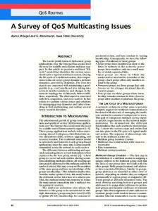
3.2 Multicasting Techniques for Single-Hop Local WDM Lightwave Networks Figure 1 depicts a single -hop WDM system that consists of N nodes such that each node is equipped with m tunable transmitters and n tunable receivers. Connectivity is achieved by tuning the receivers and/or transmitters, to a common channel, over which data is transmitted. Most MAC protocols, including those supporting multicast traffic scheduling, depend in their operation on exchanging control signals during the pre-transmission coordination phase. There are two methods for exchanging control information: out-of-band and in-band. In out-of-band control signaling, control and data flows use separate wavelength channels, while in in-band control signaling, the coordination between nodes is done within the same data channels. In general, protocols that use at least one control channel to reserve access to the remaining data channels are called reservation-based protocols, and those that use all the channels for data transmissions are called pre-allocation protocols [15]. m Tunable Transmitters/node
1
n Tunable Receivers/node
1
PSC 2
2
. .
. .
N
N
Figure 1 The generic design for the single-hop WDM networks
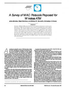
The benefits that can be gained when an efficient multicasting technique is employed in single -hop WDM networks were investigated in [16]. Using analytical models and simulation, it was shown that these advantages include, among others, increasing the throughput of the network, and improving its upper-bound performance especially if the nodes are equipped with more than one receiver. Realizing these benefits, researchers started to look for methods for supporting multicasting traffic in this topology. These methods are classified according to the classification map shown in Figure 2, which represents the framework for this survey. Mainly, the multicasting techniques are divided into two major groups of approaches based on their underlying system model: techniques designed for single -hop systems and techniques proposed for multi-hop systems. Those single-hop based techniques can be further categorized according to the transceiver type as Receiver Tuning Algorithms and Transmitter Tuning Algorithms. The former group depends on exploiting the tuning ability of the
5
Techniques for Multicast Support in Local WDM Lightwave System System Model
Multi-Hop WDM Systems
Single-Hop WDM Sy stems
Channel/node Dependent
Transceiver Type
Nodal Replacement
Channel Sharing
Receiver Tuning Algorithms
Transmitter Tuning Algorithms
[33]
[34]
Coordination basis
[32]
Scheduled Techniques
Unscheduled Techniques
No. Of Transmission Trials Per Packet
[30] [31]
Single Packet Transmission Technique [17] [18] [20] [21]
Multiple Packets Transmission Technique Hybrid Packet Transmission Technique
[22] [23] [25] [28]
[29]
Figure 2 Classification map for multicast techniques in Local WDM networks
receivers in order to transmit the multicast traffic and is used in FT-TR and TT-TR networks. In essence, the receivers are configured such that only those receivers in the multicast group are tuned to the appropriate channel used by the source node. The proposed mechanisms within this group will be discussed in detail in Section 4. On the other hand, Transmitter Tuning Algorithms are designed in order to configure the multicast source nodes to deliver the multicast packets efficiently to their destinations by tuning their transmitters to destinations’ receiving channels. Such algorithms are used in the TT-FR networks. While most of the proposed algorithms found in the literature are of the Receiver Tuning type, the Receiver-Assisted Multicasting (RAM) Protocols [32] represents the only Transmitter Tuning Algorithm, and this will be described in Section 5.
4. Receiver Tuning Algorithms Receiver tuning techniques are further classified into two subcategories based on the degree of the required coordination. The first subgroup includes those techniques that employ full coordination before packet transmission in order to guarantee collision-free transmissions and are called Scheduled Multicast Traffic Techniques. The majority of the proposed approaches belong to this category. They employ an implicit control channel [21], one explicit control channel [18] [20] [22] [23] [25], or more than one control channel [17] [31]. The second subgroup,
6
namely Unscheduled Multicast Traffic Techniques, employs no scheduling prior to packet transmissions and requires minimal coordination between the nodes. Pre-transmission coordination employs three basic strategies depending on the number of transmission trials per packet. In the first strategy, namely the single-packet transmission scheduling technique, the source node waits for all the members in the multicast group to be ready before transmitting its multicast packet. The second strategy relies on partitioning the multicast session into smaller sessions according to the availability times of the receivers. The complete delivery of multicast packet may require multiple transmission attempts. Hence, this strategy can be called multiple-packet transmission scheduling technique. The effect of this technique is that it eliminates the need of the source node to wait for all the receivers to become available, and also for some receivers to have to wait for the rest of the receivers. This reduces the total interval during which the channels are reserved but not used, and eventually achieves better wavelength throughput. The third strategy is hybrid-packet transmission scheduling technique and, as its name implies, it is a combination of the other two strategies. It is based on realizing that schemes employing multiple transmissions do not always provide the fastest delivery of the multicast packet because the availability of the network resources has a direct impact on their performance. Therefore, scheduling multicast traffic is performed dynamically as a single transmission trial or multiple transmission trials based on the status of network resources. 4.1 Scheduled Multicast Traffic Techniques: Single-Packet Transmission Methods Transmitting the multicast packet one time to all the multicast members appears to be a natural corresponding to the concept of multicast communication. Four multicasting techniques attempt to achieve this single packet mechanism and they are described in the following subsections.
4.1.1 Centralized Weighting-based Multicast Scheme [17] This scheme is one of the earliest techniques for scheduling multicast traffic in single -hop PSC-based optical networks. The system model is CC2 -FT-TR WDM network, and the tuning latency effect is ignored. Control signals are exchanged via two separate channels (λin and λout ), and both data and control channels are time slotted. The multicast scheduling algorithm is centralized. A central controller is responsible for collecting requests from the hosts attached to the network via channel λin , computes the transmission schedule, and finally broadcasts the computed transmission schedule on channel λout to all other nodes. The scheduling algorithm is based on constructing traffic matrices that represent traffic demands per channel for each time slot. Information required to build these matrices are the source address, the set of destination nodes, as well as the number of slots needed for transmission. This information is included in transmission requests received by the central controller from the nodes. However, computing these traffic matrices is constrained by the number of transmitters/receivers per node and the number of available channels. Since the number of transceivers per node in this model is one, no more than one packet is allowed to be sent/received per node. Hence, the authors represented unicast requests in terms of units (each of size one) in each matrix entry. On the other hand, the multicast packet is viewed as one single packet directed to m different destinations, where m is the multicast group size, and a multicast request is represented by m entities in the matrix entry. Each entity is pla ced in the corresponding entry of each
7
multicast member and has a weight of 1/m. Also, a new matrix entry should be created in case one or more of the system constraints is not satisfied. The simplicity of this weighting-based method is its main drawback. Results obtained from simulation experiments showed that this method was not able to satisfy its main goal, which is using the least number of slots for packet transmission. Although the results showed that the schedule obtained for the unicast traffic was almost optimal, the number of slots needed for multicast transmissions is far from optimal which implies that this technique is not adequate and it does not reflect the real nature of multicasting. Another drawback of this algorithm is that it wastes two channels to support the control flow. So, it is not a practical solution for systems that have few channels. Moreover, the centralized nature of this method forms a reliability bottleneck since the failure of the centralized controller will cause the system to fail. Also, the time between requesting the transmission and granting the permission is very long, namely, at least four times the propagation delay from the node to the PSC, in addition to the controller’s waiting time for all the requests to arrive from all nodes, and the processing time of such requests. The last latency factor is of minimal effect especially with the simplicity of the used algorithm. However, the other two factors are more significant and cannot be minimized unless the whole system design is modified. Subsequent studies recognized these shortcomings and tried to overcome most of them by using adequate alternatives, as will be shown below.
4.1.2 Multicast Scheduling Algorithm (MSA) [18] The Multicast Scheduling algorithm (MSA) proposed in [18] is unique due to many reasons. First, the authors based their work on the generic system model CC-TTm-TRn single-hop network shown in Figure 1. Therefore, this work is general and can fit any special system model. Second, they took the tuning time of the transceivers and the effect of the propagation delay into consideration. Also, the MSA is an adaptive algorithm since the scheduling is done on demand which makes it suitable for the dynamic, non-uniform and time varying nature of the multicast communication. Furthermore, unlike the model proposed in [17], the MSA is distributed and is executed by all the nodes in parallel and hence the propagation delay encountered by the signals is half that in [17]. Last but not least, the proposed algorithm is able to schedule the combined unicast and multicast traffic, because the whole network data traffic is viewed as a collection of multi-destination connections such that the unicast packets themselves are treated as multicast packets directed to multicast groups of single node memberships. In spite of these strength points of the MSA, this method has some limitations that will be demonstrated after describing the algorithm. The MSA is a reservation-based protocol that uses a dedicated channel to convey information to all nodes. Hosts are therefore able to store the state of the whole system locally. MSA is executed over the different nodes concurrently in order to determine the time and the channel of transmission for each data packet. For simplicity, the authors assumed that the nodes are placed at equal distances away from the PSC so that the propagation delay between all node pairs is identical. Like [17], the various transmission channels, including the control channel itself, are equally divided into fixed-length time intervals (slots). Transmitters are globally synchronized to the beginning of time slots on the data channels. On the other hand, control slots are further divided into N mini-slots, where N is the total number of nodes. Each control mini-slot is used by one source node only in order to send a request prior to any
8
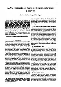
packet transmission. MSA depends on exchanging two pieces of information between all the nodes: the source address and the destination addresses. The control mini-slots are designed to accommodate this control information. A data packet is first placed in a queue at the source node, called the source arrival queue. For those packets at the head of their arrival queues, the source nodes transmit control packets on the control channel using their own control mini-slot. Upon transmission of the control packet, the associated data packet is moved to the source waiting queue until it is transmitted. Since nodes are assumed to be equally distanced from the PSC, it is guaranteed that the control packets are received by all the hosts at the same time. Upon receiving these control packets, all the hosts run the MSA in parallel. Basically, MSA uses the collected control data to determine the earliest time at which the multicast packet can be received simultaneously by all the destination nodes. MSA tries to find three timing parameters: 1) the time of the earliest free receiver for each node in the multicast group, which is determined by the latest release time of these receivers plus their tuning time, 2) the earliest free time of all the source node’s transmitters, and 3) the time for the earliest free channel. According to these parameters, MSA proceeds to determine the best channel to serve the packet. In order to eliminate the need to tune the source transmitter, MSA attempts first to schedule the packet’s transmission on the current transmitter’s home channel if it will be free within a time that is less than or equal to the time needed by the transmitter to become free and then tuned to the earliest free channel. Otherwise, the transmitter is tuned to the channel of the earliest free time. Finally, the nodes update their local data structures to reflect this reservation and to modify the free time for the corresponding transmitter, receivers and the assigned channel. After the reservation is done, MSA schedules the next incoming request for the next multicast packet that is buffered in the arriving queue. The operation of MSA is depicted in the flow chart of Figure 3. The main bottleneck of MSA is that it reserves the various network resources, i.e., channels and transceivers, until all the receivers of the remaining nodes that belong to the multicast group become free, and are hence able to receive the packet. Reserving these resources without using them by the multicast session itself or by others leads to poor transmission concurrency, and consequently low channel utilization. Other schemes tried to reduce the effect of this resource reservation, as will be described below. Because MSA is designed to schedule the transmission of a single packet only, a control packet is required to schedule the transmission of each packet. Hence, the control channel forms another bottleneck for this protocol, which limits the data channel throughput. The effect of control channels is dominant especially when the ratio of data packet size to the control packet size is small. However, this problem can be solved by operating the control channel at a higher bit rate. It is worth mentioning that an approximate analytical model of MSA was presented in [19].
4.1.3 Backtrack Multicast Scheduling Algorithm (BMSA) [20] The authors in [20] proposed a technique to overcome the wastage in the network resources that MSA suffers from by keeping the idle time for the source node, during which it waits for all the group receivers to be ready, as short as possible. The underlying system model is the generic single -hop CC-TTm-TRn system model, also employed in [18]. Unlike the MSA scheme, BMSA did not try to find the earlie st time for scheduling the multicast transmission based on the availability time of the various network components. Since this keeps the transmitter, as well as the
9
A control packet has arrived at node i
No
Step 1
Node i is a member in g ? Yes
Choose the latest release time of the receivers of the members plus their tuning time (T1 ) Step 2 Determine the earliest time at which one of the node’s transmitters would be free (T2 ) Step 3 Find the earliest time at which one of the WDM channels will be free (T3 ) Step 4 Schedule the transmission time
Channel free time for node i ≤ (T2 + Transmitter tuning delay) Step 4.1 No Step 4.1 Yes ? Schedule the packet transmission Schedule the packet transmission to to be done on the current node’s be done on the new channel home channel Step 5 Update the local data structure Figure 3 The flow chart of the MSA applied in parallel at each node i
transmission channel, idle while waiting for the receivers to become available. Instead, the authors tried to incorporate the availability times of receivers in the protocol decision for the source and channel allocation in order to minimize the waiting delay overhead. The BMSA scheme finds the best candidate time intervals to perform the multicast transmission based on the availability times of the transmitters, channels and group receivers. Transmitting a data packet takes place during these time intervals such that no resource reservation is permitted before the start of these intervals. According to [20], these unused time fragments can be used to schedule later incoming packets. This backtracking, and the reuse of the available time intervals increase the efficiency of the system performance. In order to find these time intervals, the protocol finds continuous intervals of time slots that meet the transmission requirements of the multicast packet and suit the availability times for source’s transmitter, transmission channel and destinations’ receivers. Such common free intervals form the candidates for transmitting the multicast
10
packet. However, the best-fit interval out of these candidates is chosen such that the waiting overhead is minimized; hence the channel utilization is maximized. BMSA is a distributed algorithm, which starts when a control packet request arrives at each node. First, the unused time intervals for each transmitter of the source node are determined with their upper and lower time bounds. Similarly, the time-bounded idle intervals for each receiver of the destination nodes as well as those periods for each channel are found. Accordingly, BMSA continues to find the free time intervals that are common among all the multicast session constituents. BMSA finally schedules the transmission of multicast session using the free time fragments that satisfy the following conditions: (1) it is common between all the source-based and destination-based available time intervals, (2) its length is adequate to service the multicast packet and (3) it achieves the minimum waiting overhead among all the interval candidates. This operation guarantees the delivery of packet(s) to all members by using a single transmission trial. Simulation experiments performed in [20] compared the system performance for BMSA with that of MSA. The results show that a remarkable improvement is achieved when the concept of backtracking in BMSA is applied to reuse the unused time intervals. Better system performance, in terms of channel utilization and buffer delay, is attainable over different numbers of channels. Better channel utilization may also be achieved when a greater number of tunable transceivers are used per node.
4.1.4 Simple Multicast-Type Sensitive Scheduling Algorithm [21] The last scheme is this category was proposed in [21]. The system model is the FT-TR single-hop WDM network and the channels are time-slotted. Unlike the other system models in [17], [18], and [20], all the channels are used for transmitting data traffic only while the control signaling is provided in-band; therefore, this scheme is characterized as a pre-allocation protocol [15]. Moreover, this technique ignores the tuning latency of the receivers by choosing the slot time to be equal to the packet transmission time plus the tuning time of the receiver. Also, the authors explicitly distinguished between the various kinds of traffic by classifying the slot types as unicast, multicast or broadcast in order to come up with an adaptive scheme that suits the dynamic behavior of multicast communication. The various multicast sessions were classified based on: the average length of the multicast session and the average size of the multicast group. Type-1 multicast traffic defines all the short duration multi-point sessions with large numbers of multicast group members. Such sessions can be handled using schedules based on both unicast slots for single destination packets and broadcast slots for multi destinations packets. Type-2 multicast traffic includes all the multicast sessions that are relatively short and directed to few destinations. Unicast slots only should be used to design schedules for supporting both single and/or multi-destination packets. Finally, all those sessions which are relatively long regardless of the size of their members group constitutes Type-3 multicast traffic. These sessions require traffic schedules with both unicast and multicast slots. The authors mainly concentrated on the third type. The purpose of their algorithm is to produce a traffic schedule that assigns specific multicast slots to each multicast source node. The transmissions allowed in the multicast slots are not specified in advance; instead, they are dynamically updated to reflect the current members of multicast groups. The employed timing structure of the multicast slots is shown in Figure 4. The time slots for multicast source node, i, consists of a series of combined slots that are repeated periodically and are called the periodic frame of node
11
Synch. Slot
Free Slot
λi Periodic Frame
Periodic Frame
Periodic Frame
Figure 4 An example of the timing-slots structure for node i
i. The first slot of each periodic frame is a special slot called the Synchronization Slot, and is used to (1) transfer the control traffic needed to build the schedules, hence, it acts as an in-band control channel; (2) recognize the start and end of the multicast sessions; (3) identify the destination multicast group. The synchronization slot is followed by a number of slots, called free slots, which are used by the source nodes to transmit their packets according to the calculated schedule. The number of these free slots is fixed and of critical effect on the performance of the proposed algorithm as will be shown later. The proposed algorithm works over three network elements: the transmitter i of the source node, the receiver j of the various nodes as well as the transmitter k of the hosts connected to the network other than the source. To guarantee collision-free data transmission, an efficient unicast schedule is implemented first. The multicast traffic of node i is supported by adding some slots to the original single destination schedule, called the multicast slots. The ideas behind the various algorithms are discussed here for one node, i, as the source for the multicast group. Same procedures are applied for the other multicast sources. In the synchronization slot of the periodic frame for node i, all other nodes in the network tune their receivers to node i’s transmission channel (λi ). Node i uses the synchronization slot to transmit a control packet that contains the multicast address and an indication of the start and end of multicast sessions. The subsequent time slots (free slots) of the periodic frame are then used by node i to transmit its multicast packets to its group members. If node i does not have any multicast packets to be transmitted, its free slots are then used to transmit its unicast packets. Receiving the control packets by other terminals permits these hosts to determine whether they are members in node i’s multicast group or not. If a node, call it j, belongs to i’s multicast group, then it keeps its receiver tuned to node i’s home channel in order receive multicast data during i’s free slots. However, if node j is not a member in node i’s multicast group, or if node i has no multicast packets to be transmitted, node j is able to receive the unicast traffic from another source node, e.g. k, using node i’s multicast free slots. This possibility of using the multicast slots of node i to support single -destination traffic of other nodes increases transmission concurrency and leads to enhanced channel utilization. To guarantee collision free concurrent packet transmissions, nodes i and k must use two different transmission channels and this is assured by employing the unicast schedule. This technique does not require the source node to have an advance knowledge of the members in its multicast group, and subsequently, nodes can enter and leave the multicast session whenever they wish during session’s lifetime. The algorithm is therefore insensitive to the changes in the multicast membership. In addition, the procedures that run at nodes i, j and k are simple and fast.
12
However, because these algorithms run on different sides of the network, the technique is very sensitive to the time delay between these cooperating nodes. Since the various transmitters in the network are synchronized at the beginning of each time slot and some time should elapse before node k receives node i’s control packet, node k will not be able to immediately determine whether node j is a member in node i’s multicast group or not. Consequently, some of node i’s free slots may not be used for transmitting k’s unicast traffic which leads to lower efficiency in utilizing the system free time slots. In order to make their technique less dependent on the propagation delay, the authors suggested to space the multicast slots such that the distance between two consecutive multicast slots is much larger than one slot. The size of data packet also contributes to choosing the number of free slots. Choosing this number to be large relative to the packet size forces the consecutive packets directed to the same multicast group to wait for a considerable number of slots before being transmitted using a new synchronization slot. On the other hand, a small number of free slots will waste many synchronization time slots in scheduling the same packet. Hence, the number of free slots per periodic frame must be chosen carefully in order to maximize the overall system throughput.
4.2 Scheduled Multicast Traffic Techniques: Multiple-Packet Transmission Methods Although single-packet transmission approach reduces the load on the transmitter and channel resources, it places a burden on the receivers especially when all the receivers are not available at the same time, and some of them may have to wait. The other alternative is to transmit multicast packets without waiting for all the members to be available. This subsection reviews the methods that fit into the later category.
4.2.1 Multiple Multicast Packet Transmissions Algorithm [22] The concept of partitioning the multicast transmissions based on the availability time of the receivers was first introduced in [22]. The scheme inherits all the features of [18], and also used the CC-TTm-TRn model. However, the simulation experiments are based on CC-TT-TR system model. The transceiver tuning time is assumed negligible, and transmitters are synchronized to slot boundaries. Basically, the set of receivers of a multicast group is partitioned into subgroups that receive multicast transmissions at their ready times. Every source node transmits the multicast message several times to subsets of the multicast group rather than delaying message transmission until its entire multicast group becomes available. This reduces the effect of head-of-the-line blocking at receivers which become available earlier, thus achieving better system performance. The Multicast Partitioning Problem (MPP) is formally defined as “the problem to partition a multicast group into subgroups and schedule a separate transmission for each subgroup such that the average receiver waiting time is minimized” [22]. The MPP was shown to be NP-hard, hence a number of heuristics for finding an efficient partitioning for the members’ receivers set were introduced. These algorithms are simple, fast, but require a global knowledge by the source node of the availability times of the various receivers of the multicast members. This global knowledge is guaranteed by using the control channel.
13
X1
X2
X3
S1
X1
X4
(a)
S2
X2
X3
S3
X4
(b)
S1
X1
X2
X3
X2
S4
X5 S2
X4
(c)
S1
X1
X5
S2
X5 S3
X3
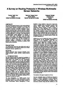
X4 X5 (d) Figure 5 Example for scheduling multiple transmissions per packet. (a) Availability time for the receivers (X1 -X5 ). (b) EAR: Four transmissions are required at: S1 for {X1 }, S2 for {X2 , X3 }, S3 for {X4 }, and S4 for {X5 } (c) LAR: Two Transmissions are scheduled at: S1 for {X1 , X2 , X3 }, and S2 for {X4 , X5 }. (d) BAR for i = 3: Three Transmissions are scheduled for the subgroups {X1 , X2 , X3 }, {X4 }, and {X5 }.
The first such heuristic is the Earliest Available Receiver (EAR), which is a greedy algorithm that schedules the first transmission to the receiver (or receivers) that becomes available first. Subsequent transmissions are scheduled immediately whenever one or more receivers become available. Figure 5-b illustrates this process for a multicast group of five receivers, X1 through X5 , which become available according to Figure 5-a. Another greedy approach is the Latest Available Receiver (LAR) algorithm which schedules a transmission at the time when the latest receiver (or group of receivers) becomes available. All receivers that become available before the latest one are then considered. Two cases arise: 1) the packet transmission to all the receivers which become available in a time slot that is earlier than the packet transmission time is delayed until the latest receiver becomes available and one single packet is then sent to all those receivers; 2) a separate packet transmission to a receiver (or group of receivers) is feasible if the availability time of this receiver is greater than packet transmission time, which guarantees that there are no conflicts with the scheduled transmission to the latest receiver. This procedure continues backwards through all the receivers in the same way until all transmissions have been scheduled. Figure 5-c shows an example of the LAR scheduling. The third heuristic is the Best Available Receiver (BAR), and employs both EAR and LAR. Each node, i, is considered in turn and scheduling the transmission starts at the time at which this node becomes available. The LAR heuristic is implemented to schedule transmissions destined to receivers that become available before node i, while EAR is used for scheduling all the transmissions for receivers that become available after i. The average waiting time is computed for this scheduling around central node i. The procedure is repeated for all the receivers in
14
the multicast group and the schedule with the minimum waiting time is eventually chosen. Figure 5-d illustrates this procedure for node i = 3. Simulation studies of such heuristics showed that they can balance the usage of transmitter and receiver resources in the network and they lead to significantly improved system performance. The authors found that the average waiting time needed by the receivers to become ready is much shorter by using these techniques than using the traditional unicast and single transmission multicast techniques. In terms of the number of scheduled transmissions, the results showed that the BAR gives near optimal behavior and that the LAR is better than EAR. Although this approach has several advantages, some aspects still need more investigation. Besides conserving the receiver resources, the other network elements, e.g., transmitters and channels, must be also considered.
4.2.2 Combinational Multicast MAC Protocol [23] The Combinational Multicast Schedule (CMS) is a reservation-based algorithm designed for the CC-FT-TR system. It operates in the slotted mode with a time slot equals to the time required for transmitting the packet in addition to the receiver tuning time. Nodes are also assumed to be equally distant from the PSC and signals arrive at the various nodes simultaneously. However, the CMS protocol is unique for many reasons. Firstly, it treats the unicast and multicast traffic separately. Secondly, the algorithm caters for the dynamic nature of multicast traffic by allowing nodes to request multicast transmissions any time and puts no restriction on joining and/or leaving times of members into/from multicast groups. Moreover, similar to [21], CMS uses the multicast session size and duration to determine its type by introducing the concept of multicast distance (M d ) which relates both multicast parameters in a quantitative manner. The distance (M) of a multicast session with duration (D) and group size (S) is calculated using vector algebra as M =
D 2 + S 2 . The relation between M d and M will be clear when describing the CMS technique.
Also, similar to [21], CMS implements a unicast-based protocol that guarantees collision-free unicast packet transmissions by: 1) pre-allocating the time slots to the tunable receivers in a manner that resolves any receiver contention, and 2) avoiding channel collision by employing an arbitration procedure that determines the access privilege of the transmission channels at each time slot. Multicast requests are exchanged using control packets. Based on multicast status information, CMS is executed by all nodes in a distributed manner, and the initial allocation of time slots, which is based on the unicast protocol, is modified to reflect the arrival of new multicast requests by reserving some of these time slots, preemptively, in order to serve multicast sessions. The procedure followed by CMS to reserve time slots for multicast packets starts when the control packet arrives at each node. If the control packet holds a request for unicast traffic only, the nodes adhere to the original unicastbased protocol. Otherwise, if the control packet has a request for transmitting one or more multicast packets, the algorithm performs: 1) multicast session qualification testing, 2) channel reservation and 3) time-slots modification. In the first step, the algorithm computes the M value of the multicast control packet and compares it to the M d value, which is a predetermined network-wide scale constant. The multicast control packet is considered to be qualified if its M value exceeds the M d . Unqualified multicast sessions are treated as unicast sessions such that each multicast packet is transmitted individually. If the multicast session passes the M d -qualification test, the algorithm
15
proceeds to perform the remaining two steps. In the second step, the unicast-based allocation of time slots is modified. Multicast sessions are given the highest priority, and the algorithm reserves the transmission channel of the source node preemptively for the multicast session. Since such a channel may be shared by more than one multicast session’s source node, access privilege of the transmission channel is given to the source node with the highest M, while randomly resolving equal M values. The number of time slots reserved for the multicast session on that channel is determined by its length. Finally, the algorithm checks the availability of the receivers of the multicast group. Because reserving time slots is performed before examining receiver availability, three cases may be encountered: 1) All receivers are available to receive the multicast packet. The algorithm removes those time slots that are already allocated by the unicast protocol to the receivers in the multicast group as they will be busy in receiving the multicast packets. The operation of nonmember nodes, and their pre-allocated time slots does not change. 2) None of the receivers is available when channel reservation is performed. Although this scenario is possible, the reference does not take it into consideration. However, such a situation may be recovered from by releasing the time slots and giving other traffic sessions (unicast or multicast) the permission to use them which increases the system efficiency. It is also possible to avoid such a situation by scheduling only one multicast transmission at a time over all channels, but this approach inhibits any concurrency in multicast communication over the various channels. Other priority-based schemes may also be used. 3) Only some of the receivers in the multicast group are available at the time of the channel reservation. The multicast group is partitioned into ready and delayed subgroups. Although reference [23] does not provide schemes for receiver partitioning, the partitioning policies proposed in [22] can still be employed. Whenever a new group of receivers becomes available, the same procedure for channel reservation and time-slot modification is executed to perform a single transmission per subgroup. M d plays a critical role in determining the system performance, as shown by simulation and by the performance model in [24]. However, more investigation on choosing this value as well as the effect of modifying it according to the changes in multicast requirements is still required. Another point that needs further studying is the possibility of utilizing the deleted pre-allocated time slots of the free members’ receiver from the unicast-based time slots map. Such time slots can be used by other traffic sessions to fill the gaps in the schedule by reassigning them to other receivers in the network.
4.2.3 Virtual Receiver-Based Multicast Technique [25] The approach presented in [25] is unique, and is designed to work with the time-slotted FT-TR WDM network model. Control signaling si performed in-band, and uses a reservation protocol like HiPeR-l [26] which is a preallocation protocol. Moreover, the tuning latency of receivers is not negligible and its effect on the schedule is taken into consideration. The authors proposed to schedule the transmission of multicast packets using a novel concept, called the virtual receiver. According to their tuning range, a set of physical receivers (PR)s which exhibit identical behaviors compose a single virtual receiver (VR), and are therefore treated as a single logical entity (receiver). By partitioning the physical receivers into a set of disjoint virtual receivers based on their tuning ability, the algorithm
16
proceeds as follows. The network multicast traffic demands are first computed from the exchanged control information. It is therefore possible that each virtual receiver may contain physical receivers that belong to different multicast groups, or that a physical receiver may be a subscriber to more than one multicast group. Then, each multic ast source detects when virtual receivers are tuned to its transmission channel. At one end of each transmission channel, the virtual receiver consists of one or more physical receivers that may belong to one or more multicast groups. On the other end, this channel can be shared by more than one multicast source node. Only those source nodes that have packets to transmit to physical receivers in the virtual receiver that is currently tuned to the source home channel transmit all its multicast packets. This step requires that: (1) the access privilege of the home channel is given only to those source nodes that have ready multicast packets while the virtual receiver contains physical receivers that belong to the multicast groups of these multicast sources, and (2) since various multicast sessions flow through the home channel to the same virtual receiver with all its physical receivers, it is the responsibility of each physical receiver to select the multicast traffic flow that is destined to it, and ignore all others. In this scheme, the authors transform the physical network into an equivalent logical network with the same number of source nodes, and channels, but with fewer or the same number of receivers. The significance of this transformation is that, since the virtual receivers are targeted by a number of packets that is equal to the sum of all the packets directed to its individual physical receivers, the multicast sessions that flow in the original physical network is effectively transformed into unicast connections in the logical network. Hence, it is possible to use any of the efficient unicast-based protocols to schedule this unicast-converted traffic. The authors use the protocol in [27] to perform such scheduling. The problem is therefore reduced to no more than finding the best partitioning of the physical receivers into virtual receivers and the authors concentrated mainly on this point. Given the set of virtual receivers, and the traffic matrix, [25] derives a lower bound on the scheduling interval, which is the maximum of: 1) the maximum duration required to transmit all the traffic from all transmitters on any given channel, taken over all the channels, and 2) the maximum duration required to transmit to all the nodes in a virtual receiver, taken over all virtual receivers, and including the tuning delays. Since finding an optimal partitioning, given the traffic matrix, is an NP-complete problem, the authors presented four heuristics for finding the virtual receiver set which will minimize the lower bound. These are based on the JOIN and SPLIT operations, in which virtual receiver sets are combined and split, respectively. Two versions of each of the two operations, namely, greedy and random, are used to arrive at the four heuristics. The numerical results presented in [25] showed that these heuristics exhibit good average performance.
4.2.4 Maximum-Destination Scheduling Algorithm [28] The last scheme that belongs to the multiple packet transmission strategy is the one that was proposed in [28]. The system model is the CC-FT-TR with negligible tuning time for the receivers and identical propagation delays between all the node pairs. The authors in [28] try to minimize the delivery time for the multicast packet (i.e. the packet delay) by transmitting it to its destination nodes as early as possible. Minimizing packet delay may result in a
17
number of different ways of partitioning the multicast transmission. The multicast transmission that consists of the least number of partitions, and thus the minimum number of the required data slots, is chosen. The author referred to this problem as the minimum-transmission problem (MTP), which they defined as: “the problem of scheduling the set of member nodes in the multicast group to receive the multicast packet such that the number of transmissions is minimum” [28]. They proved that such a problem is NP-complete. The MTP in [28] is different than the MPP defined in [22] because the objective of MPP is to minimize the average receiver waiting time while that of the MTP is to minimize the number of multicast transmissions. A heuristic scheduling algorithm was proposed in [28] for the MTP, namely the Maximum-Destination Scheduling Algorithm (MDSA). The goal of algorithm is to schedule as many destinations as possible to receive the multicast packet in each transmission trial. The MDSA operates in two modes, the initial mode and the maximum mode4 . It simply starts scheduling the multicast packet in the initial mode by finding the earliest time slot at which the multicast packet can be scheduled. This initial data slot is the first one when the source’s transmitter, the receivers (or part of them) and the source’s data channel are free. MDSA first schedules as many destination nodes as possible in this initial slot. Then, the algorithm operates in the maximum mode during which it repeatedly finds the next time slot in which the number of the available members is maximum. The algorithm stops when all the destination nodes are scheduled and the multicast packet is completely delivered. The operation of MDSA is depicted in Figure 6. The behavior of the MDSA was studied using simulation, and was compared to two other scheduling algorithms. The first one (they call it the greedy algorithm) which is similar to the MDSA in the sense that it always tries to partition the multicast session and it schedules as many destination nodes as possible at the earliest time slot but it does not attempt to minimize the number of transmission sessions. The second algorithm uses the single packet transmission approach and it delivers the multicast packet to all the receivers in one time slot, and is therefore called the no-partition algorithm. Based on the simulation results, the authors observed that the MDSA achieves lower
No New Packet ? Yes Undelivered Receivers ? Yes
Initial Mode
No
Yes
Maximum Mode
Undelivered Receivers ?
No
Figure 6 The Operation of the MDSA
4
These names are given for the sake of explaning the operation on the MDSA only and they were not used in [28]
18
packet delay than both the greedy and the no-partitioning algorithms.
4.3 Scheduled Multicast Traffic Techniques: Hybrid-Packet Transmission Method [29] The hybrid techniques that combine the previous transmission strategies (i.e. single transmission trial and multiple transmission trials) are possible too. The scheme in [29] introduced this hybrid transmission technique. This algorithm is designed for the general CC-TTm-TRn , and is reservation-based. The structure of the control frame is the same one used in [18], and the data slots include an allowance for the tuning time. The algorithm takes care of the propagation delay of the signal between the nodes; however, it assumes that such a delay is the same. This technique was inspired by the observations made in [28] regarding the fact that multiple transmission technique does not always outperform single transmission technique. The authors realized that there are many factors that affect the performance of any multicast scheduling algorithm. These factors include both the traffic conditions, such as the system traffic load and the maximum multicast group size, and the number of data channels in the system. In order to validate their argument, two packet-scheduling techniques were proposed: one by partitioning multicast transmissions and the other without any partitioning. Both algorithms are similar to the ones developed in [28]. The first one (they call it also a greedy scheme) tries to finish the multicast session as fast as possible by scheduling the transmission to as many available destination nodes as possible. The other scheduling algorithm (called the no-partition algorithm) was designed to find the earliest time slot at which the source node’s transmitter, the transmission channel, and the receivers of all the member nodes are all available. Once such a time slot is determined, the source node transmits the multicast packet using one single transmission trial. The performance of both scheduling techniques was evaluated using simulation for different numbers of channels, traffic load and membership group sizes. Based on simulation experiments, the authors concluded that knowing the utilizations of the data channels and the receivers can assist their scheduling approach. They noted that partitioning multicast group is a natural solution when the number of available data channels is sufficient because the partitioning technique increases the receiver utilization. On the other hand, when there is a shortage in the number of data channels in the system, the no-partitioning algorithm appears to be a strong candidate with its ability of delivering multicast packets to all the receivers using one data channel per data packet. Armed with these observations, a hybrid-scheduling algorithm that combines the two algorithms could be developed. The algorithm relies on the utilizations of the data channels and the receivers in order to dynamically determining whether the greedy algorithm or the no-partition algorithm is employed. Two cases were considered: (1) when the average utilization of the data channel is less than the average utilization of the receivers, and (2) when the average utilization of the data channel is greater than or equals the average utilization of the receivers. In the first case, the greedy algorithm is employed due to the abundance of data channels. The second case, however, is more sophisticated and requires more care. If the average utilization of the data channel is low, this means that there are sufficient data channels; therefore, the greedy algorithm is used. Similarly, in the other extreme, if the average utilization of the data channels is high, then the channel resources become a potential bottleneck, and the no-partition algorithm is employed. Finally, when the average channel utilization is moderate, choosing the scheduling technique depends on the impact of the scheduling algorithm on the channel resource for the upcoming data packets. The no-
19
partitioning algorithm is used if the data channels form a bottleneck for the data packet to be scheduled currently and/or for the next data packet(s). Otherwise, the greedy algorithm is chosen. Table 1 summarizes the operational conditions for the hybrid transmission technique [29]. ρ c Versus ρ r
Low ρ c
ρc < ρr ρc ≥ ρr
Medium ρ c
High ρ c
Greedy Greedy
Greedy/ No-Partition
No-Partition
Table 1 Dynamic choice between greedy and no-partition algorithms in hybrid scheduling algorithm based on ρ c and ρ r, where ρ c: Average data channel Utilization, and ρ r: Average Receivers Utilization
Simulation experiments showed that the hybrid scheduling algorithm results in the lowest mean packet delay with respect to greedy and no-partitioning algorithms. However, the reference does not mention if the hybrid algorithm will exhibit similar behavior if any of the already developed algorithms for the general CC-TTm-TRn system model were employed for the partitioning (like[22]) and the non-partitioning algorithms (like [18] or [20]).
4.4 Unscheduled Multicast Traffic Techniques [30][31] In spite of the wide employment of pre-transmission coordination, another group of researchers debated the degree that this coordination is required. They argued that although the full coordination between all nodes guarantees error-free multicast service, it also hinders hosts from fully utilizing the available transmission rates. The strategy proposed in [30] and [31] uses the least amount of coordination among all nodes prior to packet transmission, and does not use any scheduling policy. The purpose of this strategy is to produce lightweight algorithms that can be implemented on-line in high-speed environments. Because serving a multicast transmission from a group of available sessions is done randomly and no scheduling is really performed, the transmitted data can be corrupted and lost due to channel contention and/or receiver conflicts. Techniques are therefore needed to recover from such data loss. These schemes are referred to as the Unscheduled (or Random) Multicast Traffic Techniques. The work in [30] is based on a CC-TT-TR WDM lightwave PSC-based LAN system model that consists of 32 channels and 100 nodes, and a transmission rate of 10 Gigabits per second. Each node is equipped with a fast tunable transmitter and a fast tunable receiver, and as such, the effect of the tuning time of the transceivers is ignored. Two unscheduled algorithms that run on the transmitter side of the network were proposed in order to recover from channel conflicts. In the first scheme, called the Persistent Protocol, the source node keeps on transmitting the multicast packet repeatedly until it is received by all its members. This scheme prevents any other multicast session from taking place on the same channel before the completion of all earlier ones, which may degrade channel utilization. Naturally, permitting new multicast packets to be transmitted over these channels while other messages are waiting for receivers to become available enhances system performance. Therefore, the Persistent Protocol was modified by introducing a random delay between the successive transmissions of the same packet during which new multicast sessions can be initiated over the same channel. This latter scheme is called the Random Back-Off Protocol.
20
It was shown analytically (using discrete time queuing models) that both algorithms exhibit similar behaviors, but with better performance for the back-off algorithm. It is also essential to recover from any receiver conflict that may occur by choosing one of the incoming competing streams only. Simple techniques based on random selection or First Come First Served (FCFS) were used with back-off algorithm and the persistent algorithm, respectively. A more sophisticated method that is based on the idea of selecting the incoming stream that has the least number of remaining intended recipients was suggested. This selection method maximizes the probability of completing message delivery to all its destinations and hence releasing the channel for the transmission of a new message. All these algorithms proved to be promising ones. Reference [30] does not elaborate on how the source node knows which receivers had already received the message. Such ambiguity was resolved in [31], in which the conventional simple PSC-based topology was replaced by a centralized HUB-based WDM system. Instead of running the scheduling protocols over all nodes in a distributed manner, the schedules are designed to run over the central HUB itself using two separate control channels: one for the incoming requests from all the nodes to the HUB, and the other one for broadcasting the scheduling results from the HUB to all the other nodes similar to [17]. Thus, the system model is CC2 -TT-TR. Also, [31] provides a detailed analysis for the throughput of the various random protocols proposed in [30]. At the end of this subsection, it is worth mentioning that the methods proposed in [30] and [31] exploit the concept of partitioning the multicast transmissions that was introduced in [22]. This feature, however, does not contribute to our classification of Unscheduled Multicast Traffic Techniques as shown in Figure 2 because of the absence of other methods that rely on the random transmissions concept in the literature. Research in the field of unscheduled transmission techniques has just begun and more work in this area is expected.
5. Transmitter Tuning Algorithms Although the trend of the current research in the field of supporting multicast traffic in local WDM networks is towards the Receiver Tuning Algorithms due to their simple implementation, most of these techniques fail to support multicast traffic in TT-FR systems. Driven by the recent advances in the fabrication of tunable transmitter, novel multicast Transmitter Tuning Algorithms can also be proposed.
5.1 Receiver-Assisted Multicasting Protocols [32] The Receiver-Assisted Multicasting (RAM) protocols [32] are the only currently available multicast algorithm that belongs to the category of transmitter tuning multicasting techniques. The RAM protocols are reservation-based algorithms and they are the first methods designed to efficiently support multi-destination communication in timeslotted CC-TT-FR WDM systems. The RAM protocols assume that the tuning delay of the transmitters is part of the data slot, and that the nodes are equally spaced from the central PSC. Notice that tunable transmitters are much faster than tunable receivers [6], and as such, this delay is very small. The RAM protocols introduce the idea of the assistant nodes set as a novel strategy for delivering multicast traffic in single -hop WDM systems. The assistant nodes set is defined as “a set of receiving nodes that are members of the multicast group and which are capable of re-transmitting the multicast packet it receives from the original
21
source node, or other assistant nodes, to other members who have yet not received the packet”. These auxiliary sources assist the original source node to accomplish its data packet transmission sooner. The mechanism of choosing the assistant nodes set is governed by certain conditions that are called Assistance-Qualification Conditions (AQCs). In its simplest form, any node can be an assisting node if it is: (1) a member node in the multicast group, g, (2) it has already received the multicast packet in the previous transmission stages, and (3) it has no packets of its own to transmit in the current (and the subsequent) time slot(s). The operation of the assisting scheme of the RAM protocols is described as follows. Basically, the transmission of the multicast packet is divided into successive transmission stages (or correspondingly, time slots) based on the availability times of the receivers. These transmission stages start from the time at which the original source node transmits the packet for the first time, and last until the packet is completely delivered to all the members in g. Moreover, each transmission stage is composed of zero or more transmission trials for delivering the multicast packet to the currently available receivers. These transmission trials are scheduled concurrently, but on different data channels, and they originate from the multicast owner itself and zero or more assistant nodes. These parallel transmission sessions try to deliver the same packet to the remaining unserved destinations in g. This results in increasing the possibility of delivering this multicast packet to all the multicast members faster5 . Two arbitration policies were proposed in [32] in order to resolve traffic conflicts that may occur among the different simultaneous multicast sessions. Under the first policy, the priorities of transmission are based on the entry time, or the generation time of the data packet; hence, this approach is called the RAM-Entry Time Protocol. Older packets have higher transmission priority. This mechanism is improved in the second strategy by introducing some intelligence in choosing the appropriate source node per data channel. As such, the transmission priority per channel is based on the packets’ entry times, but, if the data packet of a source node is the oldest one over more than one data channel, then the source node is assigned to the data channel that has the maximum number of listening member nodes. Such a selection was performed randomly in the first RAM version. The intuition behind this technique is to increase the chance for some (if not all) of these newly received members to join the assistant nodes set provided that they meet the required AQCs, which maximizes the probability that this packet will be delivered faster. This technique is called the RAM-Number of Receivers Protocol. The effect of the number of assisting levels, where an assisting level represents a transmission stage during which more receiver nodes are allowed to assist the original source node in delivering the multicast packet, was studied using simulation. The simulation experiments showed that the receiver-assisting concept results in a tremendous reduction in the time needed to deliver a packet to all the multicast group members. It was also found that the protocols achieve the maximum possible reduction in the mean packet delay after applying a limited number of assisting levels. In addition, the number of Receivers Per Channel (RPC) has a direct impact on the system performance. When the RPC factor is high, better mean packet delay values are obtained and fewer assisting levels are required. Moreover, RPC plays a crucial role in determining the tradeoff in using either of the two RAM versions. 5
We prefer to refer to the aim of the RAM protocols as achieving three multiples (Multiple-Multiple-Multiple), i.e. RAM protocols guarantees multiple transmissions of single packet to the destination nodes by multiple source nodes over multiple (parallel) multicast connections, which results in faster packet delivery.
22
Finally, the implementation of the RAM protocols is semi-distributed such that only some operations, such as resolving the conflict for the network resources are performed by all nodes. Other functions, like determining the qualified assisting nodes per transmission trial and determining the complete delivery of the multicast packet, are performed by the original source node of the multicast session only and then are broadcast to all other member nodes.
6. Multicasting techniques for Multi-hop Local WDM networks In addition to the algorithms described earlier for local single -hop WDM networks, techniques for multi-hop systems have also been proposed in the literature. The idea behind these proposals is to deliver the multi-point packet to the various nodes- immediately or via intermediate nodes- with a minimum cost. Driven by the fact that the multi-hop scheme is a virtual topology that is used in WDM networks where the traffic demands are relatively static, [33] attempts to establish multi-point connections during the early stage of the network design. The goal was to reach an optimal design for the multi-hop network by placing the nodes in the network (or equivalently, assigning wavelengths) in such a way that minimizes the sum of the weighted hop distances of all the connections. A prior knowledge of the overall multicast traffic demands is essential. The authors proposed solutions for two special logical topologies only: bi-directional linear chain and bi-directional ring. These algorithms do not extend to other more complicated multi-hop networks, such as hypercubes or shuffle -exchange networks. The details of these algorithms as well as their points of strength and shortcomings are outside of the scope of this paper. The shortcomings of [33] were recognized in [34] by exploiting the concept of channel sharing on the generalized, shuffle -exchange-based multi-hop architecture (GEMNET) [35] which provides a wide range of system models. Channel sharing among the various nodes (either the sources or receivers) is achieved using TDM over each channel. Sharing a certain channel by some receivers enables them to simultaneously receive the same information from a single transmitter either directly or via intermediate hosts.
7. Conclusions Supporting multicast traffic in the local WDM networks has received considerable attention. This paper provides a survey of the different techniques that have appeared in the literature since 1993. The main purpose of this survey is to provide a comprehensive, and a comparative study for all those techniques that were designed to support multi-destination communication PSC-based single-hop WDM networks. In order to provide a framework that enables us to achieve this study, the protocols were classified according to the map presented in Figure 2. We started our work by providing a brief treatment of the optical networks and we then treated the major challenges and difficulties that should be handled by any multicast traffic scheduling technique. After that, the basic operation of each scheme along with its pros and cons were presented. Multicast support in multi-hop optical networks was also briefly discussed. To complete the picture, Table 2 provides a comparative summary for all the surveyed schemes.
23
Reference
System Model
Control Signaling
Scheduling Strategy
Tuning Latency
Propagation Delay
[17]
CC2FT-TR
Reservationbased
Centralized
Ignored
Ignored
[18]
CCTT m -TRn
Reservationbased
Distributed
Not Ignored
Not Ignored
Tuning (Single Per
[20]
CCTT m -TRn
Reservationbased
Distributed
Not Ignored
Not Ignored
Receiver
[21]
FT-TR
Pre-allocation
Distributed
Ignored
Ignored
Technique
[22]
CCTT m -TRn
Reservationbased
Distributed
Ignored
Ignored
[23]
CCFT-TR
Reservationbased
Distributed
Ignored
Ignored
[25]
FT-TR
Pre-allocation
Distributed
Not Ignored
Ignored
[28]
CCFT-TR
Reservationbased
Distributed
Ignored
Ignored
[29]
CCTT m -TRn
Reservationbased
Distributed
Ignored
Ignored
[30] [31]
CCTT-TR CC2TT-TR
No Coordination
Centralized
Ignored
Ignored
[32]
CCTT-FR
Reservationbased
Semi-Distributed
Ignored
Ignored
Receiver
Tuning Scheduling (Multiple Transmissions Per Packet)
Scheduling Technique Transmission Packet)
Category
ReceiverTuning Scheduling Technique (Hybrid Transmission Per Packet) ReceiverTuning Unscheduling Techniques TransmitterTuning Techniques
Table 2 Comparison between multicasting techniques in single-hop PSC-based WDM Networks.
Despite the many protocols that have appeared in the literature, there are several issues which have not been addressed. For example, practical issues such as the limited tuning range of transmitters and receivers were not taken into account. Protocols must be designed to work under such conditions. In addition, the
24
issue of prioritized station access to the medium was not considered. Such an issue is becoming more important, especially with the accommodation of different classes of service. Related to this last issue is the design of access strategies with the quality of service guarantees. These last two issues apply to virtually all types of service, including multicasting. References [1] I. P. Kaminow, “Photonic Multiple-Access Networks: Topologies”, AT&T Tech. Jour., Vol. 68, Issue 2, pp. 61-71, March 1989. [2] R. Ramaswami and K. Sivarajan, “Optical Networks: A Practical Perspective”, 2nd edition, Morgan Kaufmann, 2001. [3] J. Turner, “The Challenge Of Multipoint Communication”, Proc. 5th ITC seminar on ISDN Design and Planning, pp. 263-279, May 1987. [4] L. H. Sahasrabuddhe and B. Mukherjee, “Multicast Routing Algorithms and Protocols: A Tutorial”, IEEE Network, Vol. 14, Issue 1, pp. 90-102, Jan/Feb 2000. [5] C. K. Miller, “Multicast Networking and Applications”, Addison-Wesley, 1999. [6]J. M. H. Elmirghani, and H. T. Mouftah, “Technologies and Architectures for Scalable Dynamic Dense WDM Networks”, IEEE Communication Magazine, pp 58-66, Feb 2000. [7] G. Sahin and M. Azizoglu, “Multicast Routing and Wavelength Assignment in Wide Area Networks”, Proc. SPIE, Vol. 3531, pp. 196-208, 1998. [8] L. Sahasrabubuddhe, and B. Mukherjee, “Light trees: Optical multicasting for improved performance in wavelength routed networks”, IEEE Communications Magazine, Vol. 37, Issue 2, pp. 67–73, Feb. 1999. [9] X. Zhang, J. Wei and C. Qiao, “Constrained multicast routing in WDM networks with sparse light splitting”, Proc. IEEE INFOCOM ‘00, Vol. 3, pp. 1781–1790, May 2000. [10] J. He, S. -H. Chan and D. Tsang, “Routing and wavelength assignment for WDM multicast networks”, IEEE GLOBECOM ‘01, Vol. 3, pp. 1536–1540, 2001. [11] Y. Sun, J. Gu and D. Tsang, “Multicast Routing in All-Optical Wavelength-Routed Networks”, Optical Networks Magazine, Vol. 2, No. 4, July 2001. [12] A. E. Kamal and A. K. Al-Yatama, “Blocking Probabilities in Circuit-Switched WDM Networks Under Multicast Service”, Performance Evaluation, Vol. 47, Issue 1, pp. 43-71, Jan. 2002. [13] B. Mukherjee, “WDM- Based Local Lightwave Networks, Part I: Single-Hop Systems”, IEEE Network, Vol. 7, Issue. 3, pp. 12-27, May 1992. [14] B. Mukherjee, “WDM- Based Local Lightwave Networks, Part II: Multi-Hop Systems”, IEEE Network, Vol. 6, Issue. 4, pp. 20-32, July 1992. [15] K. M. Sivalingam and J. Wang, “Media Access Protocols For WDM Networks With On-Line Scheduling”, Jour. of Lightwave Tech., Vol. 14, Issue 6, pp. 1278-1286, Jun. 1996. [16] M. S. Borella and B. Mukherjee, “Multicasting in a WDM Local Lightwave Network”, Proc. ITC sponsored seminar on Teletraffic Analysis Methods for Current and Future Telecom Networks, pp. 71-77, Nov 1993. [17] N. Huang, Y. Wu, C. Wu and C. Chiou, “A Multicast Model For WDM-Based Local Lightwave Networks With a Passive Star Topology”, Proc. IEEE TENCON ‘93, Vol. 3, pp. 470 -473, 1993.
25
[18] M. S. Borella and B. Mukherjee, “A Reservation-Based Multicasting Protocol for WDM Local Lightwave Networks”, Proc. ICC ‘95, pp. 1277-1281, June 1995. [19] L. H. Sahasrabuddhe and B. Mukherjee, “Probability Distribution of the Receiver Busy Time in a Multicasting Local Lightwave Network”, Performance Evaluation, Vol. 33, Issue 3, pp. 149-173, Aug. 1998. [20] S. Sheu and C. Huang, “An Efficient Multicast Protocol For WDM Star-Coupler Networks”, Proc. 2nd IEEE Symposium on Computers and Communications, pp. 579 – 583, 1997. [21] G. Rouskas and M. Ammar, “Multi-destination Communication Over Tunable-Receiver Single-Hop WDM Network ”, IEEE JSAC, Vol. 15, Issue 3, pp. 501-511, Apr. 1997. [22] J. P. Jue and B. Mukherjee, “The Advantages of Partitioning Multicast Transmissions in a Single-Hop Optical WDM Network”, ICC ‘97, Vol. 1, pp. 427-431, June 1997. [23] W. Tseng and S. Kuo, “A Combinational Media Access Protocol for Multicast traffic in single-hop WDM LANs”, IEEE GLOBECOM ‘98, Vol. 1, pp. 294 -299, 1998. [24] W. Tseng, C. Sue and S. Kuo, “Performance Analysis for Unicast and Multicast Traffic in Broadcast-and-Select WDM Networks”, Proc., IEEE International Symposium on Computers and Communications, pp. 72-78, 1999. [25] Z. Ortiz, G. Rouskas and H. Perros, “Maximizing Multicast Throughput Multicast Throughput in WDM Networks with Tuning Latencies Using the Virtual Receiver Concept”, European Trans. on Telecom., Vol. 11, Issue 1, pp. 63-72, Jan-Feb. 2000. [26] V. Sivaraman and G. Rouskas, “HiPeR-l: A High-Performance Reservation Protocol with look-ahead for broadcast WDM Networks”, IEEE INFOCOM ‘97, Vol. 3, pp. 1272-1279, 1997. [27] G. Rouskas and V. Sivaraman, “Packet Scheduling in Broadcast WDM Networks With Arbitrary Transceiver Tuning Latencies”, IEEE/ACM Transactions on Networking, Vol.5, Issue 3, pp.359-370, June 1997. [28] H. Lin and C. Wang, “Minimizing the Number of Multicast transmissions in Single-Hop WDM Networks”, IEEE ICC ‘2000, Vol.3, pp. 1645-1649, 2000. [29] H. Lin and C. Wang, “A Hybrid Multicast Scheduling Algorithm for Single-Hop WDM Networks”, IEEE INFOCOM ‘2001, Vol.1, pp. 169-178, 2001. [30] E. Modiano, “Unscheduled Multicasts in WDM Broadcast-and-Select Networks”, Proc. IEEE INFOCOM ’98, Vol. 1, pp. 86 -93, Apr. 1998. [31] E. Modiano, “Random Algorithms for Scheduling Multicast Traffic in WDM Broadcast-and-Select Networks”, IEEE/ACM Transactions on Networking, Vol.7, No. 3, pp. 435-434, June 1999. [32] A. M. I. Hamad and A. E. Kamal, “Receiver-Assisting Multicasting (RAM) Protocols For PSC-Based TT-FR SingleHop Networks”, submitted for publication. [33] S. Tridandapani and J. Meditch, “Supporting Multipoint Connections in Multi-Hop WDM Optical Networks”, Jour. of High Speed Networks, Vol. 4, Issue 2, pp. 169-187, 1995. [34] S. Tridandapani and B. Mukherjee, “Channel Sharing in Multi-Hop WDM Lightwave Networks: Realization and Performance of Multicast Traffic”, IEEE JSAC, Vol. 15, Issue 3, pp. 488-500, Apr. 1997. [35] J Iness, S. Banerjee and B. Mukherjee, “GEMNET: A generalized, shuffle-exchange-based, regular, scalable and modular multi-hop network based on WDM lighwave technology”, IEEE/ACM Trans. Networking, Vol.3, Issue4, pp. 470476, Aug 1995.
26