A Systematic IP and Bus Subsystem Modeling for Platform-Based System Design. Junhyung Um, Woo-Cheol Kwon, Sungpack Hong, Young-Taek Kim, ...
A Systematic IP and Bus Subsystem Modeling for Platform-Based System Design Junhyung Um, Woo-Cheol Kwon, Sungpack Hong, Young-Taek Kim, Kyu-Myung Choi, Jeong-Taek Kong, Soo-Kwan Eo, and Taewhan Kim* CAE Center, SoC R&D, System LSI Division, Samsung Electronics, Korea
*Seoul National University, Seoul, Korea
Abstract
The topic on platform-based system modeling has received a great deal of attention today. One of the important tasks that significantly affect the effectiveness and efficiency of the system modeling is the modeling of IP components and communication between IPs. To be effective, it is generally accepted that the system modeling should be performed in two steps; In the first step, a fast but some inaccurate system modeling is considered to facilitate the simultaneous development of software and hardware. The second step then refines the models of the software and hardware blocks (i.e., IPs) to increase the simulation accuracy for the system performance analysis. Here, one critical factor required for a successful system modeling is a systematic modeling of the IP blocks and bus subsystem connecting the IPs. In this respect, this work addresses the problem of systematic modeling of the IPs and bus subsystem in different levels of refinements. In the experiments, we found that by applying our proposed IP and bus modeling methods to the MPEG-4 application, we are able to achieve 4x performance improvement and at the same time, reduce the software development time by 35%, compared to that by conventional modeling methods.
1. Introduction Reducing the time-to-market in the presence of exponentially increasing design complexity has become a critical consideration in SoC (system-on-chip) design. However, this problem presently has not been solved by traditional (e.g., ASIC) design methodologies because they are basically based on low level design abstraction, which is appropriate for simple designs. New research activities around this issue have introduced the concepts of design reuse and platform-based design methodology [1-3]. Virtual platform [4, 5] (or highly abstracted system model) based design methodology, which captures the concept of the platform-based design approach, has recently been gaining interest and recognition. The system modeling for large scale designs is (ideally) performed in two steps; In the first step, a fast, but sacrificing simulation accuracy, system modeling is performed to
3-9810801-0-6/DATE06 © 2006 EDAA
allow a concurrent development of software and hardware. The second step then refines the models of the software and hardware blocks obtained in the first step to increase the simulation accuracy for the system performance analysis. Here, one critical factor required for a successful system modeling is a systematic modeling of the IP blocks and bus subsystem since the different levels of abstraction require a different contents of IP blocks and bus subsystems. Consequently, a systematic modeling of the IP blocks and bus subsystem connecting the IPs is very important to reduce the design time as well as to increase the system performance. There are many works related to virtual platform design methodology. For performance analysis and architecture exploration, the work in [9-12] presented the design approaches to find an optimal communication architecture focusing on the IP modeling method in the transactionlevel and an exploration strategy of various communication architecture; The work in [16, 19-21] suggested several methods to adapt transaction-level modeling for architecture exploration with high simulation speed. Furthermore, several works extended the scope of the virtual platform to the embedded SW design in conjunction with hardware design. The work in [13] proposed a HW/SW co-verification method based on the integration of a C/C++ simulator and FPGA simulator, and the work in [14] proposed a parameterizable HW/SW platform that can be customized for the rapid prototyping of code compression. However, the previous works have not address the issue of systematic IP component and bus subsystem modeling, which is an essential part to be solved, especially for modeling and validating large scale SoC applications. We developed a virtual platform to support our proposed various levels of modeling of IPs and bus subsystem. As will be discussed in the case study, we applied our modeling methods to a complex mobile application that includes CPU, DSP, and more than 60 masters and slaves connected through a multi-layer bus system, showing that the simulation speed is more than one thousand times faster than that of using conventional RTL design with over 90% timing accuracy compared to the FPGA board.
Our virtual platform-based design, called ViP, is a design approach that emphasizes the systematic IP reuse for developing complex products based upon platforms and compatible hardware and software. The main features of our virtual platform are the followings: (1) ViP is modeled at the transaction-level (TL) [6-8] (these models are developed using SystemC or C++) and, thus, offers a very high simulation speed with reasonable cycle accuracy. (2) Architecture exploration and software development can happen early in the design process. (3) Software designers can prepare fully-optimized and error-minimized software before the development of RTL code.
2. IP Modeling and Verification Code reusability: We separate the functional and communication parts of each IP model to achieve systematic code reusability, as shown in Fig. 1. The main functional behavior is described in the core block while communication is totally delegated to a dedicated routine called “the communication handler,” which is prepared for various communication schemes with a unified programming interface. Therefore, all the IPs use the unified bus interface scheme, and this enables an easy adaptation to possible changes in the environment, which include a system bus or even a whole new simulation environment.
!
Fig. 1: IP modeling for reusability and productivity Classification of transaction-level IP models: In our modeling procedure, IPs are developed according to the target of the whole ViP. If the goal of the project is fully satisfied by a function-accurate ViP, we use functionaccurate IPs for that system. On the other hand, if the target requires cycle accuracy, we make all the IPs that will be integrated to the system as cycle accurate models. To support these IP modeling in the degree selection and development planning of the IP creation procedure, here we categorize IP models, as shown in Table 1, listing the features and the typical application areas for each TL model types.
Description
Features
Application Area
TL0
Functional Model
Functional description wrapped into a model. Delays for function and even communication are neglected. Fast to simulate, easy to deploy.
SW development
TL1
Parameterized transaction model
Parametric function delay (input-to-output delay). Strict communication protocol delay.
Top down Design
TL2
Cycle accurate model
Internal structures are modeled strictly. Aiming for cycle and pin accuracy.
Architecture Analysis
Table 1 Level of IP modeling
TL0 model aims for high simulation speed and early availability for SW development. In order to meet these criteria, we modeled IPs as function-accurate models and also zero-delay transactions for all communications. TL1 model has parameterized functional cycle delays suitable for top-down design flow. Changing delay parameters under architecture exploration gives more chances for retailing performance budget in the early design stage. Note that cycle delays for communication are strictly kept in this level. TL2 model reflects the structural details of the target IP, especially for bottom-up design/verification flow. Keeping micro-architectural information enables the establishment of full cycle-accuracy and even pinaccuracy. Even though this may cause a simulation performance degradation, since the bottleneck of the total simulation speed is usually the slowest model, some key components, such as memory controller and H.264 in performance analysis should be modeled as TL2. I/O interface block modeling: Our modeling strategy to enhance simulation speed is to perform detailed modeling for analysis of the crucial parts only. Since the internal structure of the I/O interface blocks usually has little effect on the analysis result, we model I/O IPs as DMAs, which perform the same in/out activities with related HW IPs. In view of the whole system, since IP models created by our method produce the same results, our modeling strategy is sufficient for system analysis. However, if we want to optimize or obtain quantitative analysis results of the I/O IPs themselves, we should create a model on a more detailed level. Furthermore, we integrate the resources of the host PC directly in our ViP environment to provide more possible usages. For example, the image data stored in the LCD module of ViP can be displayed on the monitor of host PC, and moreover, we can connect UART of the ViP to the UART of the host PC so that the various legacy software using UART can still be applied without any modification. The IP model itself should be verified against specifications or the existing HW IP. We define a three-step IP verification flow as follows. (i) Unit testing: In this step, functional verification is sufficient for the TL0 models, while timing verification is also required for the TL1 and TL2 models. It is relatively easy to write test input vectors for transaction level models, but when the RTL test benches already exist,
instead of rewriting them in TL, a co-simulation based approach is preferable [18]. This requires a transaction-topin conversion routine for a communication handler. (ii) Verification of IPs integrated with a basic subsystem: The subsystem consists of a CPU, a basic bus system, including functional memory and a bus, and an interrupt controller. We mainly focus on the verification of the interrupt controlling scheme, SFR behavior, and DMA operations between the IP and memory. We create simple software to run on the CPU and check the above behavior using the software. (iii) Full ViP verification: All developed IPs are integrated and verified together. This step will be described in section 5
3. Bus Subsystem Modeling There are several works related to bus subsystem modeling. The work in [16, 17] intensively addressed the general modeling issues related to the communication architecture in the transaction-level. In [15], AHB and APB bus of AMBA2.0 were modeled as TLM using SystemC2.0 language. They described how to raise the abstraction-level to achieve higher simulation speed. In [16], a new abstraction level called Cycle Count Accurate at Transaction Boundaries (CCATB) was introduced. CCATB is placed in between the transaction level and bus cycle accurate level to trade off simulation speed and cycle accuracy. The authors modeled AMBA AHB and AXI at CCATB and a showed simulation speed improvement over the pin-accurate SystemC model, called AHB CLI, by 1.5 times. However, they did not mention the cycle accuracy, which can be sacrificed by hiding some details in higher abstraction-levels, so it was not possible to understand the trade-off between simulation speed and cycle accuracy.
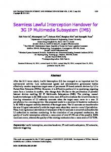
Insertion of Profiling Features
Re-definition of Protocol in Transaction-level Matching Protocols between TL and RTL Behavior Description at Transaction Port Function Description in Bus Internals / Memory Controller Design of Multi-layer Components
Optional Stage when translation
Assertion of Warning / Error Conditions
Platform Integration
Fig. 2: Flow of bus architecture design
Our virtual platform is required to have a high (more than 90%) cycle accuracy for the entire system with high
speed, which means that bus cycle accuracy should be exactly the same as the specification or legacy RTL bus system. Having these necessities in mind, to increase the simulation speed, we invent a method of systematic multistep transaction modeling. Fig.2 shows our transactionlevel modeling procedure. To model bus architecture at the transaction-level, the AHB protocol needs to be redefined as a transaction-level protocol. Bus protocol in a design specification is usually described at the signal level, so it is necessary to map signal-level protocol into TLlevel protocol, which is performed by transaction level ports (typically, transaction level ports are implemented as variables or functions). Table 2 is a mapping table of AHB. The first and third columns list the signals of AHB, and the second and fourth columns represent the corresponding variable or function of each transactionlevel port. AHB RTL
AHB Transaction
AHB RTL
HCLK
global
HTRANS[1:0]
AHB Transaction ctrl[ACC] [5:4]
HRESET
global
HPROT[3:0]
ctrl[ACC] [9:6]
HBURSREQ
requestAccess()
HSIZE[2:0]
ctrl[ACC] [12:10]
HGRANT
return value of checkForGrant()
HWRITE
read() or write() call respectively
HADDR[31:0]
read(addr, … , …) / write(addr, … , …)
HWDATA[31:0]
write(…, *data, …)
HLOCK
ctrl[ACC] [0]
HRDATA[31:0]
read(…, *data, …)
HBURST[3:0]
ctrl[ACC] [3:1]
HREADY
return value of read() or write()
Table 2 Signal to transaction-level port mapping for AHB
The next step is to model the behavior of each transaction-level port. Based on the definitions in Table 2, the behavior of each transaction-level port was modeled according to each burstX transaction scheme. Fig. 3 illustrates single transaction in AHB protocol. The procedure of sending “HBUSREQ” (bus request signal) and receiving “HGRANT” (bus grant signal) which is performed by RTL master can be represented as the following. TL-master check bus grant by “checkforgrant()” function call and if the master cannot access bus grant, it sends bus request by “requestAcess” function call. Moreover, the procedure of sending an address, checking hready, and data read can be executed by “read(addr, *data, *ctrl)” function call. In this procedure, the TL-model checks hready by the return value of “read()“ function. After designing the behavior of transaction-level ports, internal functions of the arbiter were implemented. The internal function of AHB bus delivers the request from the master ports after performing arbitration at every clock cycle. Our AHB protocol supports a fixed priority and round-robin arbitration algorithm, and we can select one of them by the SFR setting. Our modeling strategy to increase simulation speed is to perform detailed modeling for analysis crucial parts only. As for the memory subsystem, memory is modeled as a
zero-delay functional model, but we model the memory controller to reflect accurate latency at the bus boundary. That is, we categorized the pattern of the access and burst type and gave a wait cycle so that the data movements between the bus and the memory controller could satisfy the cycle accuracy. This is valid if the usage of memory subsystem is limited to give an accurate bus access pattern to the whole system. On the other hand, if the main target of the analysis is memory structure itself, memory also should be modeled in a more detailed way. In a complex system, for the bus system efficiency, we use multi-layer structure to distribute bus traffic and minimize the bus access wait of each master. In addition, to enhance the performance of memory access, we connect number of buses to the memory using a bus matrix and set the memory map to support concurrent memory bank accesses. We also modeled these features and integrated them into our bus subsystem. �� ����� �
RT Level
������������ ����������� ��������� ��������� � ����� ����
�
address phase
��5
data phase
��� �
Table 3 summarizes the cycle count ratio. We used the execution cycle count of ME as a baseline. From the results, we can see that the next derivative design greatly outperforms the current design, and according to a quantitative result, we decided to adopt next derivative. The performance improvement is mainly caused from the use of VLC and a direct data pass from DCTQ output to VLC in Fig.5. Then, we are interested in locating some parts of software for performance optimization. We performed profile analysis in a deeper level, and a summary of results is shown in Table 4. From the results, we were able to find the software places to improve, and in fact, we achieved 4x performance improvement. Initialization ME
�
��� � !�" � !�# $ % �& � �� ' (�)��*)��*)��*)�� � +� �, �� + %�- )�� ������. ��� /&01/�01/&0 � 2�+ �� � ! ! �� �' (3� � ����' � ��� ( % �4& � � ' ��� �� ( ��5*��56��5 Transaction ��� ��' ���� ��( % �4� � ��' ��� � ( ��5*��5 � +� �, � + %�- ����� % �4� � � 4���� ' � � 4&��� ' � ��� (74&��� ' � �� � ( Level 8������� �����9�����:�����;�������=< ����� �>< �������
Fig. 3: Single transaction
Intra ? Yes DCTQ
MC S/W Part H/W Part FIMV1.0: S/W FIMV2.0: S/W & H/W
Fimv 1.0 DCTQ/VLC separately operate
Fimv2.0 DCTQ/VLC operate at the same time
VLC Making Bitstream
Fig. 4: Flow of MPEG-4 video encoder
��5
�� ����� �
No
VLC &
MPEG4 HW
Initialization
ME
MC
DCTQ
FIMV1.0 (Previous)
4.52 (7%)
1 (1.5%)
1.58 (2.3%)
3.01 (4.3%)
59.5 (85.5%)
FIMV2.0 (Optimized)
4.52 (25.3%)
1 (5.6%)
1.58 (8.8%)
1.75 (9.7%)
8.98 (50.0%)
Make Bitstream
Table 3: The cycle count ratio of FIMV1.0/FIMV2.0
4. Case Study: MPEG-4 Codec We tested our proposed system modeling and verification methodology to a contemporary mobile design to illustrate how our methodology with a systematic IP and bus subsystem modeling influences the real world SoC design process. The effectiveness of the proposed modeling and verification methods is assessed by checking the capability of the performance analysis and SW development for multi-core designs. Capability of performance analysis: We analyzed the performance of MPEG-4 codec using a cycle accurate ViP. Performance was measured in terms of clock speed. Our main considerations are: (1) comparing previously developed MPEG-4 HW IPs with our enhanced ones; (2) locating parts of software to improvement through systematic quantitative analysis; (3) optimizing the performance of software. To compare the previous and current MPEG-4 HW IPs, a general MPEG-4 video reference SW, 11 I frames, and 6 P frames with Akiyo video sequences were used. Fig. 4 shows the flow diagram of the MPEG-4 video encoder. FIMV1.0/FIMV2.0 indicates the previous/current MPEG-4 hardware IPs. We created virtual platforms for both cases.
Frame
I frame
Operation
(%)
Bottleneck
Initialization
68.7
- Parameter Initialization - Non-necessary parameter assignment - Non-necessary memory allocation
DCTQ/VLC
13.3
Making Bitstream
18
Writing bitstream (DCTQ to Memory)
SW Part : 86.7%, HW Part : 13.3%
Initialization
P frame
25.2
ME MC DCTQ/VLC
5.6 8.8 9.7
Making Bitstream
50
- Parameter Initialization - Non-necessary parameter assignment - Non-necessary memory allocation
- Motion vector VLC - Writing Bitstream (Motion vector to VLC and DCTQ VLC to HW)
SW Part : 75.2%, HW Part : 24.8%
Table 4: Profile analysis – FIMV2.0 I/P Frame
SW development in multi-core design: We developed an audio software using virtual platform and shortened the software development time by 35%. Our target audio software runs on a CPU and a DSP subsystems. The CPU does most of control operations, while the DSP’s job is to decode the audio. Short messages (commands and replies) are sent via communication box registers, and large data transfers are done through DMA. The most time-consuming part in our modeling process was the
verification of the communication part between the CPU and DSP subsystem. In the verification process, first we tested CPU subsystem, which consists of the CPU core, dummy memory, and the basic bus subsystem; that is, we only integrated a minimal set of audio-related IPs. Using simple software ran on the CPU, we checked the interrupt scheme and basic data movement through DMA. Then, to test the DSP subsystem alone, we used a self-checking program to verify the interface between peripherals. These tests gave us a clear indication of the functionality of the peripherals. The self-checking tests were “standalone.” These are DSP programs that do not require external stimuli. After testing two subsystems separately, we checked the interface between two subsystems using simple Inter-Processor Communication (IPC) software. The problematic parts were message handling IPs. Actually, we spend most of the time verifying these parts. As for the final functionality test, we ran public-domain audio decoding software to check the entire functionality. We could not hear the audio sound directly because simulation speed was too slow for real time audio processing. Instead, we saved decoded PCM audio data to a file and converted it to a wave file using an audio converter. Finally, to develop a cycle accurate model, we refined the model, and Table 5 shows a cycle count comparison between the functional and cycle accurate models. The comparison indicates that the functional model significantly reduces the simulation time. ViP (for SW) Simulation Environment Total Cycle Count
ViP (for Analysis)
CPU subsystem + DSP subsystem SW : Test Audio Software 7,699,730 cycles
35,748,518 cycles
Table 5: Results for cycle count comparison
5. Conclusions In this paper, we proposed a systematic IP component and bus subsystem modeling methodology for practical platform-based system modeling to target complex and large scale SoC designs. Our virtual platform (ViP) integrating the various details of modeling capability of IPs and bus subsystem makes it possible to prototype, for example, the SW on a platform running more than 1000 times faster than RTL design and to reduce the overall design time by starting the SW before the RTL design is completed. It is also worthwhile to mention that our system modeling does not aim to replace the FPGA based verification stage, but aims to shift many issues in earlier design stages to reduce the design iterations by lowering the critical issues in later design stages. Acknowledgment: This work is supported by Samsung Electronics, and the work of T. Kim is supported by the
Ministry of Science and Technology / Korea Science and Engineering Foundation through the Advanced Information Technology Research Center (AITrc).
References [1] K. Keutzer, et al., “System-level design: orthogonalization of concerns and platform-based design”, IEEE TCAD, 2000. [2] A. Sangiovanni-Vincentelli, et al., “Benefits and challenges for platform-based design”, DAC, 2004. [3] G. Smith, “Platform based design: Does it answer the entire SoC challenge?”, DAC, 2004. [4] S. Brini, et al., “A flexible virtual platform for computational and communication architecture exploration of DMT VDLS modems”, DATE, 2003. [5] J. Notbauer, et al., "Verification and management of a multimillion-gate embedded core design”, DATE, 1999. [6] L. Cai and D. Gajski, “Transaction level modeling: an overview”, CODES, 2003. [7] I. Moussa, et al., “Exploring SW performance using SoC transaction-level modeling”, DAC, 2003. [8] A.K. Deb, et al., “System design for DSP applications in transaction level modeling paradigm”, DAC, 2004. [9] R. Jindal and K. Jain, "Verification of transaction-level SystemC models using RTL testbenches," in Proc. of First ACM and IEEE International Conference on Formal Methods and Models for Co-Design, 2003. [10] N. Calazans, et. al., "From VHDL register transfer level to SystemC transaction level modeling: a comparative case study," in Proc. of 16th Symposium on Integrated Circuits and Systems Design, 2003. [11] I. Moussa, et al., "Exploring SW performance using SoC transaction-level modeling," DATE, 2003 [12] K. Lahiri, et al. “LOTTERYBUS: A new high-performance communication architecture for system-on-chip designs,” DAC, 2001 [13] Y. Nakamura, et al., “A fast hardware/software Coverification method for System-on-a-Chip by using a C/C++ simulator and FPGA emulator with shared register communication”, DAC, 2004 [14] H. Lekatsas, et al., ”Coco : A hardware/software platform for rapid prototyping of code compression technologies”, DAC, 2003 [15] M. Caldari, et. al., “Transaction-Level Models for AMBA Bus Architecture Using SystemC 2.0”, DATE, 2003 [16] S. Pasricha, et al., "Extending the transaction level modeling approach for fast communication architecture exploration," DAC, 2004. [17] M. Bombana, F. Bruschi, “SystemC-VHDL co-simulation and synthesis in the HW domain”, DATE, 2003 [18] A. Sayinta, et al., “A Mixed abstraction level co-simulation case study using SystemC for System on Chip verification”, DATE, 2003. [19] O. Ogawa et al, “A practical approach for bus architecture optimization at transaction-level”, DATE, 2003 [20] AHB CLI Specification www.arm.com/armtech/ahbcli [21] Maxsim, AXYS Design Inc.,mhttp://www.axysdesign.com