920
IEEE PHOTONICS TECHNOLOGY LETTERS, VOL. 23, NO. 13, JULY 1, 2011
A Temperature-Insensitive Twist Sensor by Using Low-Birefringence Photonic-Crystal-Fiber-Based Sagnac Interferometer Peng Zu, Chi Chiu Chan, Yongxing Jin, Tianxun Gong, Yifan Zhang, Li Han Chen, and Xinyong Dong
Abstract—An optical fiber twist sensor is proposed by using solid core low birefringence photonic crystal fiber (LB-PCF)-based Sagnac interferometer. The twist effects on the fiber are theoretically analyzed. The results show that the dip wavelength of the transmission spectrum shifts with the twist angle with a high sensitivity and resolution of 1.00 nm and 0.01 , respectively. The sensor is also insensitive to environmental temperature change with an ultralow thermal dependent coeffiecient of 0.5 pm C. Index Terms—Birefringence, low-birefringence photonic crystal fiber, optical fiber twist sensor, Sagnac interferometer.
which was different from the experimental result of the sensor based on HBF. In addition, various fiber gratings were also used to perform twist sensing [9], [10]. Besides, twist sensors based on two modes operation in HBF [11] and in-fiber polarimeters were also reported [12]. In this letter, a LB-PCF based SI is used to demonstrate the twist sensing. The principle, sensor scheme, results and conclusion are discussed in the following sections. II. ANALYSIS TWIST EFFECTS ON THE FIBER
I. INTRODUCTION
S
AGNAC interferometer (SI) has been intensively investigated as sensors for various parameters sensing such as strain, pressure, temperature, twist and so on [1]–[5]. Recently, with the development of photonic crystal fibers (PCFs), performance of the sensors based on SI with PCF are greatly improved such as sensitivity [1], [5], flexibility [1] and thermal dependence [4]. High-birefringence fibers (HBFs) or polarization-maintaining fibers (PMFs) are commonly used in the SI to introduce birefringence for producing a wavelength dependent output for various measurements. For the sensors based on SI, most attentions were paid on linear birefringence effect caused by strain [4], pressure [2], core deformation [3] and so on. However, circular birefringence effect is also important and worthy for attention. Twist effect on the fiber is one of the major causes of the circular birefringence in some situations. Various high birefringent photonic crystal fibers (HB-PCFs) were used in the Sagnac loop to realize the twist sensors. A linear relationship between the spectrum shift and the twist angle was obtained with a sensitivity of 0.06 nm [5] and nm [6]. Low-birefringence fiber (LBF) was also employed in the Sagnac loop. J.M. Estudillo-ayala analyzed the twist effects on the LBF in the SI [7]. Y.X. Jin mentioned the twist induced spectrum shift in single mode fiber (SMF) based SI was a sinusoidal function [8], Manuscript received January 25, 2011; revised March 22, 2011; accepted April 09, 2011. Date of publication April 19, 2011; date of current version June 15, 2011. P. Zu, C. C. Chan, Y. Zhang, and L. H. Chen are with the School of Chemical and Biomedical Engineering, Nanyang Technological University, Singapore 637459, Singapore (e-mail:
[email protected]). Y. Jin and X. Dong are with the Institute of Optoelectronic Technology, China Jiliang University, Hangzhou 310018, China. T. Gong is with the School of Electrical and Electronic Engineering, Nanyang Technological University, Singapore 637553, Singapore. Color versions of one or more of the figures in this letter are available online at http://ieeexplore.ieee.org. Digital Object Identifier 10.1109/LPT.2011.2143400
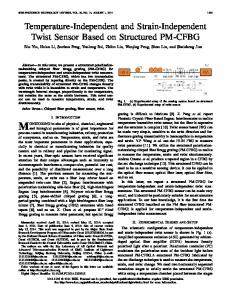
In a real optical fiber, the core area is often not perfectly circular symmetry due to residual stress which leads to the intrinsic linear birefringence . When the fiber is twisted, core deformation and shear strain give rise to a component of linear birefringence and circular birefringence, respectively. The total effects of the twisted fiber can be treated as a retarder and a rotator [13]. By fixing one end of the fiber and twisting on the other end, the retardance between the two orthogonal guided modes is expressed as a function of twist angle which is given as [13]: (1) where (2) (3) is the twisted fiber length. is the strain induced optical rotation which is proportional to and given as: (4) where is a constant which depends on the photoelastic coef. If ficients of the material. For a single mode fiber, the center of the fiber is twisted while both ends of the fiber are fixed, the twisted effects are doubled and twice of the twist angle ( ) is used in the equations. The simulation results are shown in Fig. 1. For the case of HBF, the linear birefringence is greater than circular birefringence induced by the twist effect [13]. Little amount of light couples between the two polarized modes, thus the twisted fiber acts as a rotator [13]. Then retardance varies linearly with the twist angle periodically in every linear region (Fig. 1).
1041-1135/$26.00 © 2011 IEEE
ZU et al.: TEMPERATURE-INSENSITIVE TWIST SENSOR BY USING LB-PCF-BASED SAGNAC INTERFEROMETER
921
Fig. 3. Variation trend of measured transmission spectra at different twist angles. Inset: measured transmission spectra at twist angles of 0 and 60 .
by the transverse force over the length of on the PCF. is the operating wavelength. If a broadband light is launched, a wavelength-dependent sinusoidal interference fringe is observed (the inset in Fig. 3). When the LB-PCF is twisted, the fringe will be shifted due to the extra circular birefringence and phase difference caused by the twist. In this case, the total phase difference can be expressed as . Considering is a constant, the spectrum shift is given by
Fig. 1. Calculated fiber retardance as a function of twist angle .
Fig. 2. Sensing scheme based on LB-PCF for twist measurement. (ASE: Amplified spontaneous emission light source.) Inset: SEM image of the cross section of the PCF (LMA-10).
For the case of LBF, the intrinsic linear birefringence is smaller than the circular birefringence [13]. The retardance becomes (5) which can be described by a Sinc function ( mately (Fig. 1).
) approxi-
III. SENSOR STRUCTURE AND OPERATION PRINCIPLE The schematic diagram of the twist sensor is shown in Fig. 2. The configuration was based on a SI which was obtained by splicing a section of 50-cm-length solid core LB-PCF (LMA-10, NKT Photonics A/S) with the two output ports of a 3-dB SMF coupler (Fig. 2). The scanning electron graph (SEM) in Fig. 2 shows a hexagonal arrangement of air-holes around the solid core in the cross section of the PCF which is approximately circular symmetric. The core, cladding, and mode field diameters are 10 m, 125 m, and 7.5 m, respectively. The total splicing loss between SMF and PCF is about 4 dB. The 3-dB coupler splits the light into two beams counterpropagating along the loop and recombines them again. Subsequently, the two beams interfere at the 3-dB coupler. If the insertion loss in the loop is neglected, the relative transmission ratio is given as [4]: (6) In the absence of birefringence of the loop, the total phase difference , so . All the input light of all the wavelengths would reflect back completely to the input port of the ideal 3-dB coupler and no signal will appear on the port which is connected to optical spectrum analyzer (OSA). A transverse force is applied on the LB-PCF for introducing an initial linear birefringence which will lead to a constant phase difference . is the linear birefringence induced
(7) For the case of HBF, the simulation result (Fig. 1) and the experimental results in [4], [5] show that, the coefficient is a constant, so is linearly proportional to the twist angle . On the other hand, for the case of LBF, is following a pattern of Sinc function. The sensitivity of the sensor depends on the coefficient . Thus, the use of the LB-PCF is one of the best choices for the proposed sensor to improve the torsion sensitivity. It is because of its air-hole structure, the sensor based on PCF is more sensitive to fiber twist effects than traditional fibers [5], [6]. Moreover, if the HBF is used for this proposed sensing scheme, the circular birefringence caused by the twist effects will be greatly swamped by the large linear birefringence of HBF itself [13]; hence the twist sensor based on LBF will achieve a higher torsion sensitivity than the one based on HBF. Finally, the ultralow thermal dependence property of the PCF will decrease the influence of the ambient temperature variation and increase the torsion sensitivity. IV. EXPERIMENTAL RESULTS AND DISCUSSION A length of 20-mm PCF, together with a balanced fiber, was clamped between two metal plates in order to introduce the necessary initial birefringence. The force applied on the PCF was adjusted until a dip on the transmission spectrum appeared on the OSA (AQ6370) within the range of the amplified spontaneous emission (ASE, 1520–1620 nm) light source. The curve indicated by “0” in Fig. 3 shows the initial transmission spectrum with the wavelength of the dip at 1578.1 nm. While the PCF was twisted from its center clockwise (CW) or counterclockwise (CCW), the transmission spectrum shifted to the shorter or longer wavelength side, respectively, which was completely reversible and repeatable. The inset in Fig. 3 shows the measured transmission spectra at the twist angles of 0 and 60 . In order to obtain the twist sensitivity of the sensor, the transmission spectra were recorded by increasing the twist angle from 0 to 360 with an interval of 10 . It shows the dip wavelength shifts periodically and the variation trend is similar
922
IEEE PHOTONICS TECHNOLOGY LETTERS, VOL. 23, NO. 13, JULY 1, 2011
Fig. 5. Dip wavelength shift at different temperatures. Fig. 4. Dip wavelength shift with the twist angle.
to Sinc function by the 3-D diagram in Fig. 3. The visibility of the transmission spectrum varies totally about 10 dB during the applied twist effect. The reason is that the splitting ratio of the coupler depends on the wavelength and polarization state [14], so the practical splitting ratio slightly deviates from 3 dB, which causes the decrease in the visibility of the interference fringes. Moreover, the change of the dip wavelength in the spectrum of the proposed sensor is used to measure the twist effect, so the performance of the sensor is not affected by the variation on the visibility of the transmission spectrum. The relationship between the dip wavelengths and twist angles is shown in Fig. 4. The dip wavelength shifted 52.7 nm from the minimum wavelength 1545.2 nm at the twist angle of 60 to the maximum wavelength 1597.9 nm at the twist angle of 140 in the first period, which is 3 times larger than the wavelength shift range of the twist sensor by employing SMF [8]. Comparing the results of the sensors based on PCF and SMF, the variation trends were similar, but PCF was more sensitive to the twist effect [8]. The curve is fit with a Sinc function by a high value of 0.9898, which means the experimental data are in accordance with the simulation results. Taking the linear range from 75 to 140 as an example, linear fit was applied to the curve with a high value of 0.9937, which means the dip wavelength increased with a good linearity. The sensitivity in this linear region is 1.00 nm . In practical application, the sensor can be pretwisted to this linear range for achieving a high sensitivity measurement. The achieved sensitivity of this proposed twist sensor is 17 times and 12.5 times higher than that of the twist sensor by use of HB-PCF [5] and PM- side hole fiber [6] based SI, respectively, 521 times higher than that of the polarization mode interferometer by means of fabrication two in-line polarizers on the hollow core PCF [12], 255 times higher than that of ultra long-period LPG [15]. Moreover, the resolution of the twist sensor is measured as 0.01 at the limit resolution of the OSA of 10 pm. Another distinct advantage of this twist sensor based on PCF is the ultralow temperature sensitivity, which is confirmed in the experiment. Fig. 5 shows the dip wavelength moved about 40 pm to the shorter wavelength side when the temperature increased from 30 C to 100 C. The temperature coefficient is obtained as pm C which can be neglected comparing to the high twist sensitivity of 1.00 nm . V. CONCLUSION A twist sensor by employing a section of LB-PCF inserted in the SI is proposed and experimentally demonstrated. The sensor has a sinusoidal wavelength-dependence output with the assistance of the transverse force applied on the LB-PCF which is used for introducing initial necessary linear birefringence. The
transmission spectrum shift is a Sinc function form which is different from the result of the twist sensor by employing HBF. The sensor achieved a large enhanced sensitivity of 1.00 nm and a high resolution of 0.01 with a good repeatability. The temperature-insensitive property was also confirmed experimentally with an ultralow temperature coefficient of pm C. REFERENCES [1] B. H. Kim, S. H. Lee, A. X. Lin, C. L. Lee, J. Lee, and W. T. Han, “Large temperature sensitivity of Sagnac loop interferometer based on the birefringent holey fiber filled with metal indium,” Opt. Express, vol. 17, pp. 1789–1794, Feb. 2009. [2] H. Y. Fu, H. Y. Tam, L. Y. Shao, X. Y. Dong, P. K. A. Wai, C. Lu, and S. K. Khijwania, “Pressure sensor realized with polarization-maintaining photonic crystal fiber-based Sagnac interferometer,” Appl. Opt., vol. 47, pp. 2835–2839, May 2008. [3] O. Frazao, J. M. Baptista, and J. L. Santos, “Recent advances in high-birefringence fiber loop mirror sensors,” Sensors, vol. 7, pp. 2970–2983, Nov. 2007. [4] X. Y. Dong, H. Y. Tam, and P. Shum, “Temperature-insensitive strain sensor with polarization-maintaining photonic crystal fiber based Sagnac interferometer,” Appl. Phys. Lett., vol. 90, p. 3, Apr. 2007. [5] H. M. Kim, T. H. Kim, B. Kim, and Y. Chung, “Temperature-insensitive torsion sensor with enhanced sensitivity by use of a highly birefringent photonic crystal fiber,” IEEE Photon. Technol. Lett., vol. 22, no. 20, pp. 1539–1541, Oct. 15, 2010. [6] O. Frazao, S. O. Silva, J. M. Baptista, J. L. Santos, G. StatkiewiczBarabach, W. Urbanczyk, and J. Wojcik, “Simultaneous measurement of multiparameters using a Sagnac interferometer with polarization maintaining side-hole fiber,” Appl. Opt., vol. 47, pp. 4841–4848, Sep. 2008. [7] J. M. Estudillo-Ayala, J. Ruiz-Pinales, R. Rojas-Laguna, J. A. AndradeLucio, O. G. Ibarra-Manzano, E. Alvarado-Mendez, M. Torres-Cisneros, B. Ibarra-Escamilla, and E. A. Kuzin, “Analysis of a Sagnac interferometer with low-birefringence twisted fiber,” Opt. Lasers Eng., vol. 39, pp. 635–643, May/Jun. 2003. [8] Y. X. Jin, C. C. Chan, Y. F. Zhang, X. Y. Dong, and P. Zu, “Temperature sensor based on a pressure-induced birefringent single-mode fiber loop mirror,” Meas. Sci. Technol., vol. 21, p. 065204, Jun. 2010 [Online]. Available: http://iopscience.iop.org/0957-0233/21/6/065204 [9] X. Chen, K. Zhou, L. Zhang, and I. Bennion, “In-fiber twist sensor based on a fiber Bragg grating with 81 tilted structure,” IEEE Photon. Technol. Lett., vol. 18, no. 24, pp. 2596–2598, Dec. 15, 2006. [10] W. G. Zhang, G. Y. Kai, X. Y. Dong, S. Z. Yuan, and Q. D. Zhao, “Temperature-independent FBG-type torsion sensor based on combinatorial torsion beam,” IEEE Photon. Technol. Lett., vol. 14, no. 8, pp. 1154–1156, Aug. 2002. [11] O. Frazao, C. Jesus, J. M. Baptista, J. L. Santos, and P. Roy, “Fiberoptic interferometric torsion sensor based on a two-LP-mode operation in birefringent fiber,” IEEE Photon. Technol. Lett., vol. 21, no. 17, pp. 1277–1279, Sep. 1, 2009. [12] H. F. Xuan, W. Jin, M. Zhang, J. Ju, and Y. B. Liao, “In-fiber polarimeters based on hollow-core photonic bandgap fibers,” Opt. Express, vol. 17, pp. 13246–13254, Jul. 2009. [13] A. Barlow, J. Ramskov-Hansen, and D. Payne, “Birefringence and polarization mode-dispersion in spun single-mode fibers,” Appl. Opt., vol. 20, pp. 2962–2968, 1981. [14] K. Morishita and K. Yamazaki, “Wavelength and polarization dependences of fused fiber couplers,” J. Lightw. Technol., vol. 29, no. 3, pp. 330–334, Feb. 1, 2011. [15] Y. J. Rao, T. Zhu, and Q. J. Mo, “Highly sensitive fiber-optic torsion sensor based on an ultra-long-period fiber grating,” Opt. Commun., vol. 266, pp. 187–190, Oct. 2006.


![([PDF]) Word Twist EPUB By - Google Sites](https://m.moam.info/img/260x300/pdf-word-twist-epub-by-google-sites_6477f24b097c47a9708c477b.jpg)


