readers to the different network security controls including the network
architecture, protocols, standards and software/ hardware tools that have been
adopted in ...
A Tutorial on Network Security: Attacks and Controls Natarajan Meghanathan Assistant Professor of Computer Science Jackson State University Jackson, MS 39217, USA Phone: 1-601-979-3661; Fax: 1-601-979-2478 E-mail:
[email protected] Abstract With the phenomenal growth in the Internet, network security has become an integral part of computer and information security. In order to come up with measures that make networks more secure, it is important to learn about the vulnerabilities that could exist in a computer network and then have an understanding of the typical attacks that have been carried out in such networks. The first half of this paper will expose the readers to the classical network attacks that have exploited the typical vulnerabilities of computer networks in the past and solutions that have been adopted since then to prevent or reduce the chances of some of these attacks. The second half of the paper will expose the readers to the different network security controls including the network architecture, protocols, standards and software/ hardware tools that have been adopted in modern day computer networks.
1. Introduction to Computer Networks With the phenomenal growth in the Internet, network security has become an integral part of computer and information security. Network security comprises of the measures adopted to protect the resources and integrity of a computer network. This section reviews the basics of computer networks and Internet in order to lay a strong foundation for the reader to understand the rest of this paper on network security.
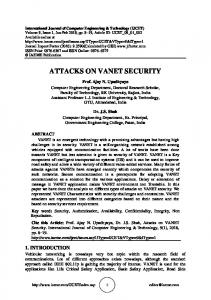
1.1 ISO-OSI Reference Model The communication problem in computer networks can be defined as the task of transferring data entered by an application user in one system to an application user in another system through one or more intermediate networks [1]. The communication problem is solved using a layered approach through a collection of protocols forming the so-called protocol suite. Each layer, dealing with a particular aspect of the communication problem, is implemented with a particular protocol and the protocols co-operate with each other to solve the entire communication problem. The Open Systems Interconnection (OSI) model [2] is an abstract representation of the basic layers (as stated below and also shown in Figure 1, in top to bottom order) involved to solve the communication problem: Application, Presentation, Session, Transport, Network, Data-link and Physical layers. The application layer specifies how one particular application uses a network and contacts the application program running on a remote machine. The presentation layer deals with the translation and/or representation of data at the two end hosts of the communication. The session layer is responsible for establishing a communication session with a remote system and it also handles security issues like password authentication before the application user can connect to the remote system. The transport layer provides end-to-end, reliable or best-effort, in-order data packet delivery along with support for flow control and congestion control. The network layer deals with forwarding data packets from the source to the destination nodes of the communication. The data-link layer deals with the organization of data into frames and provides reliable data delivery over the physical medium. The physical layer provides the
encoding/decoding schemes and the modulation/demodulation schemes for the actual transmission of data, over the physical medium, as a sequence of bits of 1s and 0s.
Figure 1: OSI Model
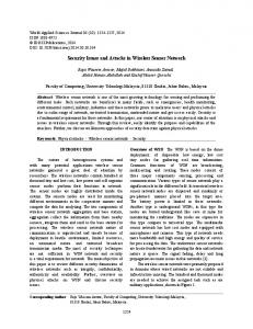
Figure 2: TCP/IP Protocol Stack and the Structure of a Data Packet
1.2 TCP/IP Protocol Stack The seven-layer OSI model is conceptual: it shows the different activities required for communication between application programs running in two different hosts. Its full implementation will result in excessive overhead and will lead to huge delays in data delivery at the destination [1]. The TCP/IP (Transmission Control Protocol/ Internet Protocol) protocol stack [3], shown in Figure 2, is the commonly used model for wide area communications, like the Internet. The TCP/IP protocol stack is composed of the Application, Transport, Internet and the Link layers (from top to bottom). The application layer of the TCP/IP model is in-charge of the responsibilities of the application, presentation and session layers of the OSI model. The transport layer of the TCP/IP model is similar to the transport layer of the OSI model. The Internet layer takes care of addressing and routing the data packets across different heterogeneous networks. Each machine and router in the Internet has a unique IP address. The link layer of the TCP/IP model combines the functionalities of the data-link layer and physical layer of the OSI model. The link layer supports the organization of data into frames and their encoding/decoding mechanisms. The structure and transmission of the frames depends on the topology and hardware technology (like Ethernet, Token Ring and etc) used for the network. A data packet is referred to as segment, datagram and frame at the transport, internet and the link layers respectively.
1.3 TCP Connection Establishment The two commonly used transport layer protocols in the TCP/IP protocol stack are the Transmission Control Protocol (TCP) [3] and the User Datagram Protocol (UDP) [3]. TCP is a connection-oriented, byte-stream based protocol and provides reliable, in-order data delivery. UDP is a connectionless, message-based protocol and provides only best-effort service for end-to-end data delivery. Processes running TCP have to establish a connection before exchanging any data packet. During this connection establishment mechanism, the two processes exchange information about the capabilities and resources available at their respective hosts for the particular communication session that is about to begin. This will help the TCP process running in one host to adjust its data sending rate according to the resources (like the memory buffer space) available for the TCP process at the receiving host. In order to avoid replay errors, the two processes pick an arbitrary starting sequence number for the data packets sent by them. Each byte of data is given a unique, monotonically increasing sequence number. The sequence number of a data packet sent using TCP represents the sequence number of the first byte of the data transmitted in that packet. The TCP connection-establishment process (shown in Figure 3) is a three-way handshake mechanism [1] and is explained as follows through this example: Let a process running in host A initiate a session with a process at host B by sending a Synchronization (SYN) packet to host B with the initial sequence number set to X. The process at host A will include information about the memory resources available
(through the ‘Advertised Window’ field of the TCP header) in the SYN packet. If the process at host B is willing to establish a communication session with the process at host A, then it sends back a SYN/ACK packet that will indicate the memory resources available at host B for this communication, the starting sequence number of the data packets coming from the process at host B and an acknowledgment for receiving the SYN packet from the process at host A. The process at host A will respond back with an ACK packet if it accepts to the advertised window value of host B and is willing to tune down its data sending rate accordingly. Note that the acknowledgment sent to a process/host for receiving a packet with a particular sequence number (say X) indicates the sequence number (X+1) of the next packet expected from the process/host. Typically, host A could be a client and host B could be a server.
Figure 3: TCP Connection Establishment Mechanism
1.4 Internet Control Message Protocol (ICMP) IP provides best-effort service in delivering datagrams from one host to another host through one or more intermediate networks. The TCP/IP protocol suite provides an error-reporting protocol called the Internet Control Message Protocol (ICMP) that operates in tandem with IP. IP uses ICMP to report errors and certain critical information to the end hosts. Each ICMP message is identified by an 8-bit type field in the IP header. One of the commonly used ICMP message is ECHO Request/Reply [4]. An ECHO request message is sent to the ICMP process running on a host computer to check whether the host is alive. If the host is alive, the host sends a response using the ECHO Reply message.
2 Classical Network Attacks In this section, we describe some of the classical attacks that have exploited the typical vulnerabilities of computer networks and the solutions deployed to combat or reduce the chances of some of these attacks.
2.1 Threats in Transit The network interface card (NIC) [5] of each host in a network is uniquely identified with a hardware address. The NIC will be programmed to pick up only the packets addressed to: (i) The unicast hardware address corresponding to the host, (ii) The multicast hardware address corresponding to the multicast group in which the host is a member of and (iii) The broadcast hardware address. A capable intruder can reprogram the NIC with the hardware address of another host and accept packets addressed to that host. To avoid being caught, the intruder can put a copy of the packet back to the network. Wiretapping [6] is the process of extracting information as it flows through a wire. The process of wiretapping differs depending on the communication medium used. In cables, wiretapping can be done through the use of a packet sniffer or through inductance. A packet sniffer [7] is a computer software or hardware that can intercept the traffic passing through a local area network (LAN) cable. A packet sniffer can be used for both beneficial and malicious purposes: (i) To analyze network problems and monitor network usage, (ii) To filter suspect content from network traffic, (iii) To study the structure of the packet
headers of the different protocols used over the network, (iv) To detect network intrusion attempts and (v) To gather information for effecting a network intrusion. As an ordinary wire emits radiation during the propagation of electrical signals through it, an intruder can tap the wire and read radiated signals through inductance without making physical contact with the cable. An intruder intercepting the signals on a broadband cable has to separate the targeted signal from all the multiplexed signals. Wireless signals are broadcast through the open space and are more susceptible for tapping. For example, the signal path of microwave signals has to be fairly wide to make sure the antenna of the receiver will be hit by the transmitted signal. But, the wider the signal path, the more it is easy for an intruder to interfere with the line of sight of transmission between the sender and the receiver and also to pick up the entire transmission from an antenna located closely to the receiver. Similarly, with satellite communication, there is a tradeoff between coverage and secure communication. A footprint [6] is defined as the pattern produced on the surface of the earth from the satellite’s transmitter. A broader footprint is needed to maximize coverage because the signals can be picked up over a huge region. On the other hand, a smaller footprint is desirable to reduce the risk of interception. The angle of dispersion of a satellite transponder is a parameter that could be controlled to adjust the spread of a footprint. An optical fiber, made of thin glass strands, can carry light pulses over long distances without being much affected by electrical interference [6]. Optical fibers are more secure than any other transmission media because of the following two reasons: (i) Optical fibers are fine tuned to achieve total internal reflection. So, the entire network should be retuned to facilitate tapping and interception and (ii) Optical fibers carry light energy and not electrical signals. So, inductance based tapping would not be possible.
2.2 TCP Session Hijacking TCP session hijacking [8] refers to the act of taking over an already established TCP session and injecting packets into the stream that are processed by the receiver as if the packets are coming from the authentic owner of the session. A TCP session is identified by the quadruple: client IP address, client port number, server IP address and server port number. Any packet that reaches either machine with the above identifiers is considered to be part of the existing session. If attackers can spoof these items, they can pass TCP packets to the client or server and have those packets processed as coming from the other machine.
Figure 4: Desynchronizing a TCP Session
Figure 5: Creating a TCP ACK Storm
To successfully hijack an existing TCP session, an attacker has to first desynchronize the session and then inject the intended commands. To desynchronize an existing TCP session (refer Figure 4) between a client and server, the attacker has to first predict the sequence number that is about to be used by a client
(or server) and use that sequence number before the client (or server) gets a chance to use. If the attacker has access to the network, a packet sniffer can be used to look into the packets belonging to the TCP session and one can accurately predict the expected sequence number from the ACK packets exchanged. If the attacker cannot sniff the TCP session between the client and server, then the attacker has to try all possible options and guess the expected sequence number. When the attacker successfully hijacks the TCP session and injects own spoofed data packets (as if the data packets are coming from the original client), the server will acknowledge the receipt of the data packet to the original client by sending it an ACK packet. As this ACK packet will most likely bear a sequence number that is not expected by it, the original client will attempt to resynchronize with the server by sending it an ACK packet with the sequence number that it is expecting. This ACK packet will in turn contain a sequence number that the server is not expecting and so the server will resend its last ACK packet. This cycle will continue and the rapid passing back and forth of the ACK packets creates the TCP ACK storm (refer Figure 5). As the attacker injects more and more data packets, the size of the ACK storm increases and can quickly bring down performance of the network. After a certain number of unsuccessful resynchronization attempts, the original client eventually gets exhausted and closes the connection with the server.
2.3 Man in the Middle Attack With a Man-In-The-Middle (MITM) attack [8], an attacker can read, modify and insert messages between two communicating parties, without either party knowing that the link between them has been compromised. To successfully carry out this attack, one must be able to observe and intercept messages between the two victims. We now describe an example for an MITM attack on public-key cryptography. Let A and B be the two communicating parties and let M be the attacker who wants to deliver a false message to B. To get started, B sends its public key to A. If M can intercept the communication channel between A and B, then M gets access to the public key of B. Then, M sends A, a spoofed message that claims to have come from B. In this message, M sends its own public key, but A thinks it has received the public key of B. When A sends a data packet to B, it encrypts the packet with (what A considers as) the public key of B and inserts the encrypted message in the channel. M intercepts the message and decrypts it with its own private key to extract the actual message sent by A to B. M then encrypts the message with the public key of B. Note that M could even modify the message before encrypting it again. M inserts the new encrypted message back in the channel so that the message can go to B. B decrypts the message using its own private key and reads the message assuming it came from A.
2.4 Echo-Chargen Attack Chargen (Character Generator) [9] is a protocol of the TCP/IP protocol stack and is used for testing and performance measurement purposes. Chargen runs on TCP port 19 and also on UDP port 19. When a client opens a TCP connection with a server on TCP port 19, the server starts sending arbitrary characters back to the client, until the TCP connection is closed. Whenever a host sends a UDP message to a server on UDP port 19, the server responds back with an arbitrary message and the number of characters in the message will be in the range [0…512].
Figure 6: A Typical Echo-Chargen Attack An attacker can trigger the Echo-Chargen attack by spoofing a conversation between the Echo Request/Reply service and the Chargen service and then redirecting the output of each service to the other, creating a rapidly expanding spiral of traffic in the network. In Figure 6, we see an attacker
triggering the attack by sending a spoofed message to one of the targeted hosts (host A) running the Chargen service at UDP port 19. The message is spoofed in such a way that it appears to have originated from the other targeted host (host B) and UDP port 7, which is the port number used for EchoRequest/Reply messaging. Host A now sends a UDP message from port 19 to port 7 of host B. Host B will consider this as an Echo Request message and sends back a Reply message to UDP port 19 of host A. Host A will treat the Reply message as a message received for the Chargen service and sends back a new arbitrary UDP message to port 7 of host B. This cycle of message exchange between the two services will continue and generate excessive traffic in the network. Eventually, the attack consumes memory and processor power at the two targeted hosts A and B and causes them to become non-responsive to user commands.
2.5 Smurf Attack A perpetrator can launch the Smurf attack [8] by sending a spoofed Echo-Request message to a network’s broadcast IP address. The spoofed Echo-Request message has the victim’s IP address as the source IP address. Hence, each host receiving the broadcast Echo-Request message will send an Echo-Reply message to the victim. The victim will be overwhelmed with a flood of Echo-Reply messages. Thus, the Smurf attack is a kind of Denial-of-Service (DoS) attack. Two solutions have been currently adopted in the Internet to prevent a Smurf attack [10]: (i) Routers do not forward datagrams having the destination address as a broadcast IP address and (ii) Hosts are configured not to reply for Echo-Request messages that were received as a broadcast message.
2.6 Traffic Redirection A compromised router can send out route update messages to all its neighboring routers informing them that it lies on the shortest path to every network in the Internet [11]. The neighboring routers forward all of their incoming data packets to this compromised router, which will get eventually flooded with the data packets and starts dropping them. The data packets do not make it to the destination.
2.7 Attacks on Domain Name Service (DNS) A DNS server is a machine that holds a table (called the DNS cache) mapping the domain names to IP addresses [12]. The server queries other DNS servers higher up in the domain name hierarchy to resolve domain names for which it does not have an IP address entry in its DNS cache and updates its cache with the mapping learnt. DNS cache poisoning [13] is an attack using which the DNS server is made to believe a domain name-IP address mapping as authentic, while, in reality, it is not. Once the DNS cache is poisoned, the entry stays for a while in the cache and affects the clients who use the DNS server in the mean time. For example, an attacker can replace the IP address information for a target file server with the IP address of a compromised file server which the attacker controls. The attacker creates fake entries in the compromised server with file names matching those on the target server. These files could contain malicious contents such as a worm or virus. Users who want to download files from the target file server may end up unknowingly downloading files with malicious content from the compromised file server.
2.8
Distributed Denial of Service (DDoS) Attacks
DDoS attacks [8] involve breaking into hundreds or thousands of machines all over the Internet. The attacker installs malicious software on all these compromised machines (called zombies) and controls them to launch coordinated attacks on victim sites. DDoS attacks are normally aimed at exhausting the network bandwidth, overwhelming a router’s processing capacity and breaking network connectivity to the victims. The attacker uses any convenient method (like exploiting the buffer overflow attack [6] or
tricking the victim to open and install an unknown code from an email attachment) to plant a Trojan Horse [6] on a target machine and transform it into a zombie by also installing a rootkit software. The rootkit helps to conceal the presence of the Trojan Horse and hide its malicious activities. After forming sufficient number of zombies, the attacker sends a signal to all the zombies to launch the DDoS attack on a chosen victim machine. Each zombie may launch the same or a different type of attack on the victim.
2.9 Syn Flood Attack During the TCP connection establishment process, the server maintains a SYN_RECV queue to keep track of the connection requests for which it has allocated the resources and responded back with a SYN/ACK message, but the corresponding ACK from the client has not yet been received. The server eventually times out waiting for the ACK packet and removes the incomplete connection request from its queue. An attacker can launch a DDOS attack by sending several SYN connection request messages using spoofed non-existing IP addresses and never respond back with the ACK messages [8]. The SYN_RECV queue of the server gets filled up with incomplete connection request messages. Even though these incomplete connection requests are discarded after the timeout, if a genuine client attempts to establish a TCP connection with the server in the mean time, the server discards the SYN request from that client.
3
Network Security Controls
This section describes several network security controls that have been adopted in modern day computer networks to combat the threats and prevent or reduce the chances of an attack.
3.1 Link Encryption Vs End-to-End Encryption Encryption applied between every pair of hosts connected by a link is called link-to-link encryption [6]. Link encryption is preferred when all the hosts in the network are secure, but the communication medium is shared among several users and is not secure. Almost all the components of a data frame (except the source and destination hardware addresses in the frame header) are encrypted before the frame is inserted onto the physical communications link. As the frame reaches the next hop receiver (could be a router or the end host), the frame is decrypted at the bottom protocol layer and sent to the higher layers for further processing and forwarding. Since encryption is at the bottom protocol layer, the message is exposed in plaintext at all the other layers of the sender and receiver and at the link and Internet layers of the intermediate hosts for hardware addressing and routing. Thus, link encryption protects the message in transit between two computers, but the message is in plaintext inside the end hosts and the intermediate hosts. One or more of the intermediate hosts may not be credible. Table 1: Comparison of Link Encryption and End-to-End Encryption Link Encryption End hosts of every link should share a key and should be able to do encryption and decryption If there are N hosts and n users in a network (N