Domain map: Ï: ΩI â ΩJ where â may be replaced with any mapping symbol ..... Floca, R., Dickhaus, H.: A flexible registration and evaluation engine (f.r.e.e.).
A Unified Image Registration Framework for ITK� Brian B. Avants1 , Nicholas J. Tustison2 , Gang Song1 , Baohua Wu1 , Michael Stauffer1 , Matthew M. McCormick3 , Hans J. Johnson4 , James C. Gee1 , and The Insight Software Consortium5 1
5
Penn Image Computing and Science Lab, Dept. of Radiology University of Pennsylvania, Philadelphia, PA, 19104 2 Dept. of Radiology and Medical Imaging, University of Virginia, Charlottesville, VA 22903 3 Department of Psychiatry The University of Iowa, IA 52242 4 Kitware, Inc., Clifton Park, NY 12065 http://www.insightsoftwareconsortium.org
Abstract. Publicly available scientific resources help establish evaluation standards, provide a platform for teaching and may improve reproducibility. Version 4 of the Insight ToolKit ( ITK4 ) seeks to establish new standards in publicly available image registration methodology. In this work, we provide an overview and preliminary evaluation of the revised toolkit against registration based on the previous major ITK version (3.20). Furthermore, we propose a nomenclature that may be used to discuss registration frameworks via schematic representations. In total, the ITK4 contribution is intended as a structure to support reproducible research practices, will provide a more extensive foundation against which to evaluate new work in image registration and also enable application level programmers a broad suite of tools on which to build.
1 Introduction As image registration methods mature—and their capabilities become more widely recognized—the number of applications increase [20,22,21,16,5,6,3,19,15,13,8,17]. Consequently, image registration transitioned from being a field of active research, and few applied results, to a field where the main focus is translational. Image registration is now used to derive quantitative biomarkers from images [11], plays a major role in business models and clinical products (especially in radiation oncology) [6], has led to numerous new findings in studies of brain and behavior (e.g. [4]) and is a critical component in applications in pathology, microscopy, surgical planning and more [21,16,9,5,6,19,13,17]. Despite the increasing relevance of image registration across application domains, there are relatively few reference algorithm implementations available to the community. One source of benchmark methodology is the Insight ToolKit (ITK) [24,1], which marked a significant contribution to medical image processing when it first emerged �
This work is supported by National Library of Medicine sponsored ARRA stimulus funding.
B.M. Dawant et al. (Eds.): WBIR 2012, LNCS 7359, pp. 266–275, 2012. c Springer-Verlag Berlin Heidelberg 2012 �
A Unified Image Registration Framework for ITK
267
over 10 years ago. Since that time, ITK has become a standard-bearer for image processing algorithms and, in particular, for image registration methods. In a review of ITK user interests, image registration was cited as the most important contribution of ITK (personal communication). Numerous papers use ITK algorithms as standard references for implementations of Demons registration and mutual information-based affine or BSpline registration [22,21,9,5,6]. Multiple toolkits extend ITK registration methods in unique ways. Elastix provides very fast and accurate B-Spline registration [14,17]. The diffeomorphic demons is a fast/efficient approximation to a diffeomorphic mapping [23]. ANTs provides both flexibility and high average performance [2]. The BrainsFit algorithm is integrated into slicer for user-guided registration [13]. Each of these toolkits has both strengths and weaknesses [14,17] and was enabled by an ITK core. The Insight ToolKit began a major refactoring effort in 2010. The refactoring aimed to both simplify and extend the techniques available in version 3.x with methods and ideas from a new set of prior work [12,7,20,16,19,2]. To make this technology more accessible, ITK4 unifies the dense registration framework (displacement field, diffeomorphisms) with the low-dimensional (B-Spline, Affine, rigid) framework by introducing composite transforms, deformation field transforms and specializations that allowed these to be optimized efficiently. A sub-goal set for ITK4 was to simplify parameter setting by adding helper methods that use well-known principles of image registration to automatically scale transform components and set optimization parameters. ITK4 transforms are also newly applicable to objects such as vectors and tensors and will take into account covariant geometry if necessary. Finally, ITK4 reconfigures the registration framework to use multi-threading in as many locations as possible. The revised registration framework within ITK is more thoroughly integrated across transform models, is thread-safe and provides broader functionality than in prior releases. The remainder of the document will provide an overview of the new framework via the context of a potential general nomenclature. We also establish performance benchmarks for the current ITK4 registration. Finally, we discuss future developments in the framework.
2 Nomenclature The nomenclature below designates an image registration algorithm pictorially. This nomenclature is intended to be a descriptive, but also technically consistent, system for visually representing algorithms and applications of registration. Ideally, any standard algorithm can be written in the nomenclature below. A physical point: x ∈ Ω where Ω is the domain, usually of an image. An image: I : Ω d → Rn where n is the number of components per pixel and d is dimensionality. A second image is J. Domain map: φ : ΩI → ΩJ where → may be replaced with any mapping symbol below. Affine mapping: ↔ a low-dimensional invertible transformation: affine, rigid, translation, etc. Affine mapping: → designates the direction an affine mapping is applied. Deformation field: � deformation field mapping J to I. May not be invertible.
268
B.B. Avants et al.
Spline-based mapping: � b e.g. B-Spline field mapping J to I. Diffeomorphic mapping: � these maps should have an accurate inverse that is computed in the algorithm or can be computed from the results. Composite mapping: φ = φ1 (φ2 (x)) is defined by �→ where φ2 is of type �. Not invertible: � indicates a mapping that is not invertible. Image warping: For example, → J represents applying affine transform → on image J. → J = J(A(x)). Similarity measure: ≈ s or ≈s indicates the metric s that compares images. We would then write a standard Demons registration application that maps one image, J, into the space of I (presumably a template) as: I �→ J
which symbolizes
I ≈ J(A(φ(x))),
with A an affine mapping and φ a generic deformation. The notation means that the algorithm first optimizes an affine mapping, →, between J and I. This is followed by a deformation in the second stage,�, from → J to I. In terms of transformation composition, we would write �→ J = Jw (x) = J(φAffine (φDemons (x))) where Jw is the result of warping J to I. The φ are the specific functions corresponding to the schematic arrows. Note, also, that the tail of the arrow indicates the transform’s domain. The arrowhead indicates its range. Finally, we denote the similarity metric as ≈ which indicates a sum of squared differences (the default similarity metric). ITK4 sup≈ , or cross-correlation, ≈ ports metrics such as mutual information, mi cc. We will use this nomenclature to write schematics for registration applications in the following sections.
3 Overview of the Unified Framework The key ideas for ITK4 registration are: 1. Registration maps can be applied or optimized through the itkCompositeTransform which chains transforms together as in Figure 1. 2. Each ITK4 transform has either global support (affine transform) or local (or compact) support (a displacement field transform). If any map in a composite transform has global support then the composite transform has global support. 3. ITK4 metrics are applicable to both types of transforms and may optimize over dense or sparse samples from Ω. Metrics may be multi-channel (e.g. for registering RGB or tensor images). 4. The optimization framework is multi-threaded and memory efficient to allow highdimensional transformations to be optimized quickly on multi-core systems. 5. The ITK4 optimization framework comes with parameter setting tools that automatically select parameter scales and learning rates for gradient-based optimization schemes. These parameter setting tools use physical units to help provide the user with intuition on the meaning of parameters. Below we will discuss (1) gradient-based optimization within the framework, (2) techniques to estimate optimization parameters for arbitrary metric and transformation combinations and (3) a generalized diffeomorphic matching approach.
A Unified Image Registration Framework for ITK
(a) a.img
I
b.img (b)
x y J(A(φ(x))) z
(d)
269
J
J(A(x))
(c)
I �→ J
I→J
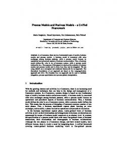
Fig. 1. Define x in ΩI and z in ΩJ as the same material point but existing in different domains. The point y is in a domain that is intermediate between ΩI and ΩJ . The standard approach in the ITKv4 registration framework is to map image J (b) to image I (a) by first identifying the linear transformation, →, between the images, shown in (c). Second, we remove the shape (diffeomorphic) differences (d). Consequently, we have a composite mapping, computed via the mutual information similarity metric, that identifies I(x) ≈mi J(A(φ(x))) = JAffine (y) = J(z). The image JAffine (y) represents J after application of the affine transformation A i.e. J(A(x)).
3.1 Optimization Framework The general ITK4 optimization criterion is summarized as: Find mapping φ(x, p) ∈ T such that M (I, J, φ(x, p)) is minimized.
(1)
While, for functional mappings, this formulation is not strictly correct, the practical implementation of even high-dimensional continuous transformations involves parameterization. The space T restricts the possible transformations over which to optimize the mapping φ. The arguments to φ are its parameters, p, and the spatial position, x. Note that, in ITK4 , the image I may also contain a mapping, although it is not directly optimized in most cases. As will be seen later in the document, this mapping may also be used within large deformation metrics. The similarity metric, M , is perhaps the most critical component in image registration. Denote a parameter set as p = (p1 , p2 . . . pn ). The metric (or comparison function between images) is then defined by M (I, J, φ(x, p)). For instance, M = �I(x) − J(φ(x, p))�2 i.e. the sum of squared differences (SSD) metric. Its gradient with respect to parameter pi is (using the chain rule), Mpi =
∂M ∂J(φ(x, p)) ∂φ T ∂M = |x . ∂pi ∂J ∂φ ∂pi
(2)
This equation provides the metric gradient specified for sum of squared differences (at point x) but similar forms arise for the correlation and mutual information [10].
270
B.B. Avants et al.
Both are implemented in ITK4 for transformations with local and global support. The ∂J(φ(x,p)) ∂φ term is the gradient of J at φ(x) and ∂p is the Jacobian of the transformation ∂φ i taken with respect to its parameter. The transform φ(x, p) may be an affine map i.e. φ(x, p) = Ax + t where A is a matrix and t a translation. Alternatively, it may be a displacement field where φ(x, p) = x + u(x) and u is a vector field. In ITK4 , both types of maps are interchangeable and may be used in a composite transform to compute ≈ � registrations that map to a template via a schematic such as I ≈→ J, I mi b → J, ≈ I cc �→ J or, mixing similarity metrics, I ≈cc �≈mi → Ji . The most commonly used optimization algorithm for image registration is gradient descent, or some variant. In the above framework, the gradient descent takes on the form of ∂M ∂M φ(pnew , x) = φ(pold + λ [ ,··· , ], x), ∂p1 ∂pn where λ is the overall learning rate and the brackets hold the vector of parameter updates. Note that, as in previous versions of ITK, a naive application of gradient descent will not produce a smooth change of parameters for transformations with mixed parameter types. For instance, a change Δ to parameter pi will produce a different magnitude of impact on φ if pi is a translation rather than a rotation. Thus, we develop an estimation framework that sets “parameter scales” (in ITK parlance) which, essentially, customize the learning rate for each parameter. The update to φ via its gradient may also include other steps (such as Gaussian smoothing) that project the updated transform back to space T . Multi-threading is achieved in the gradient computation, transformation update step and (if used) the regularization by dividing the parameter set into computational units that correspond to contiguous sub-regions of the image domain. 3.2 Parameter Scale Estimation We choose to estimate parameter scales by analyzing the result of a small parameter update on the change in the magnitude of physical space deformation induced by the transformation. The impact from a unit change of parameter pi may be defined in multiple ways, such as the maximum shift of voxels or the average norm of transform Jacobians [12]. Denote the unscaled gradient descent update to p as � p. The goal is to rescale � p to q = s· � p, where s is a diagonal matrix diag(s1 , s2 . . . sn ), such that a unit change of qi will have the same impact on deformation for each parameter i = 1...n. As an example, we want �φ(x, pnew ) − φ(x, pold )� = constant regardless of which of the i parameters is updated by the unit change. The unit is an epsilon value, e.g. 1.e-3. ∂φ ∂M ∂M ∂J(φ(x,p)) ∂φ Rewrite [ ∂M [ ∂p1 , · · · , ∂p ]. To determine the relative ∂p1 , · · · , ∂pn ] as ∂J ∂φ n scale effects of each parameter, pi , we can factor out the constant terms on the outside of the bracket. Then the modified gradient descent step becomes diag(s) ∂φ ∂p . We identify the values of diag(s) by explicitly computing the values of �φ(x, pnew ) − φ(x, pold )� with respect to an � change. A critical variable, practically, is which x to choose for evaluation of �φ(x, pnew ) − φ(x, pold )�. The corners of the image domain work well for affine transformations. In contrast, local regions of small radius (approximately 5) work well for transformations with local support. Additional work is needed to verify
A Unified Image Registration Framework for ITK
271
Fig. 2. An ITK diffeomorphic mapping of the type I � J. The “C” and 1/2 “C” example illustrate the large deformations that may be achieved with time varying velocity fields. In this case, the moving (deforming) image is the 1/2 “C”. The right panels illustrate the deformed grid for the transformation of the “C” to 1/2 “C” (middle right) and its inverse mapping (far right) which takes the 1/2 “C” to the reference space. The unit time interval is discretized into 15 segments in order to compute this mapping. 15*5 integration steps were used in the Runge-Kutta ode integration over the velocity field. A two core MacBook Air computed this registration in 110 seconds. The images each were of size 150 × 150.
optimal parameters for this new ITK4 feature. However, a preliminary evaluation is performed in the results section. The new parameter scale estimation effectively reduces the number of parameters that the user must tune from k + 1 (λ plus the scales for each parameter type where there are k types) to only 1, the learning rate. The learning rate, itself, may not be intuitive for a user to set. The difficulty—across problem sets—is that a good learning rate for one problem may result in a different amount of change per iteration in another problem. Furthermore, the discrete image gradient may become invalid beyond one voxel. Thus, it is good practice to limit a deformation step to one voxel spacing [12]. We therefore provide the users the ability to specify the learning rate in terms of the maximum physical space change per iteration. As with the parameter scale estimation, the domain over which this maximum change is estimated impacts the outcome and similar practices are recommended for both cases. This feature is especially useful for allowing one to tune gradient descent parameters without being concerned about which similarity metric is being used. That is, it effectively rescales the term λ∂M/∂p to have a consistent effect, for a given λ, regardless of the metric choice. 3.3 Diffeomorphic Mapping with Arbitrary Metrics Beg proposed the Large Deformation Diffeomorphic Metric Mapping (LDDMM) algorithm [16] which minimizes the sum of squared differences criterion between two images. LDDMM parameterizes a diffeomorphism through a time varying velocity field that is integrated through an ode. In ITK4 , we implement an alternative to LDDMM that also uses a time varying field and an ode but minimizes the following objective function: � 1 �Lvt �2 dt . (3) E(v) = M (I, J, φ1,0 ) + w 0
This is an instance of equation 1 where w is a scalar weight and φ1,0 is a standard integration of the time-varying velocity field vt which is regularized by linear operator L.
272
B.B. Avants et al.
ITK4 uses Gaussian smoothing which is the Green’s kernel for generalized Tikhonov regularization [18]. This objective is readily optimized using an approach that is similar to that proposed by Beg. Generalization of the LDDMM gradient for other metrics basically follows [10] with a few adjustments to accomodate diffeomorphic mapping. Figure 2 shows an ITK result on a standard example for large deformation registration. We will evaluate this diffeomorphic mapping, along with parameter estimation, in the following section.
4 Evaluation We first investigate the ability of our automated parameter estimation to facilitate parameter tuning across metrics. We then compare ITK4 with an open-source ITK3 registration application. In the future, the latest evaluation numbers will be available at: ITKv4 latest evaluation results. Parameter Estimation across Metrics. ITK4 provides similarity metrics that may be applied for both deformable and affine registration. In a previous section, we provided a parameter estimation strategy that is applicable to both deformable and affine transformations with arbitrary metrics. Denote images I, J, K, where the latter two are “moving” images, and K is an intensity-inverted version of J. We then evaluate the following schema, I ≈�→ J,
I ≈cc �→ K,
I ≈mi �→ K
where, for each schematic, we use the corresponding metric for both affine and diffeomorphic mapping. Furthermore, we keep the same parameters for each registration by exploiting parameter scale estimators. Figure 3 shows the candidate images for this test. As shown in figure 3, very similar results are achieved for each schematic without additional parameter tuning. To determine this quantitatively, we perform registration for each schematic and then compare the Dice overlap of a ground-truth three-tissue segmentation. For each result, we have the Dice overlap of dark tissue (cerebrospinal fluid, CSF), medium intensity tissue (gray matter) and bright tissue (white matter). For the mean squares metric, we have: 0.588, 0.816 and 0.90; for CC, we have: 0.624, 0.786, 0.882; for MI, we have: 0.645, 0.779, 0.858. Mutual information does best for the CSF while mean squares does best for other tissues. CC performs in the mid-range for all classes of tissue. Thus, a single set of tuned parameters provides a reasonable result for an affine plus diffeomorphic mapping across three different metrics. While improvement might be gained by further tuning for each metric, this result shows that our parameter estimation method achieves the goal of reducing user burden. Comparison against ITK3 . We compare the ITK4 registration against an ITK3 registration suite BrainsFit (nitrc.org multimodereg). We present preliminary, encouraging evaluation results for this approach to gradient descent with both affine and deformable registration in Figure 4. The dataset consists of ten elderly and demented subjects with manual labels of brain parenchyma. Of importance is that the ventricles are not included in the parenchyma. Large deformation is required to match ventricles and, as such, this evaluation provides some insight into the benefit of the new ITK4 diffeomorphic matching.
A Unified Image Registration Framework for ITK
273
I
J
K
SSD
CC
MI
Fig. 3. Three references images, I (left), J (middle top), and K (right top), are used to illustrate the robustness of our parameter scale estimation for setting consistent parameters across both metrics and transform types. K is the negation of J and is used to test the correlation and mutual information registrations. We optimized, by hand, the step-length parameters for one metric (the sum of squared differences) for both the affine and deformable case. Thus, two parameters had to be optimized. We then applied these same parameters to register I and K via both correlation and mutual information. The resulting registrations (bottom row) were all of similar quality. Further, the same metric is used for both affine and diffeomorphic mapping by exploiting the general optimization process given in equation 1.
5 Discussion and Future Work ITK is a community built and maintained toolkit and is a public resource for reproducible methods. The updated ITK4 registration framework provides a novel set of user-friendly parameter setting tools and benchmark implementations of both standard and advanced algorithms. Robustness with respect to parameter settings has long been a goal of image registration and ITK4 takes valuable steps toward the direction of automated parameter selection. By the time of the workshop, we intend to have a more extensive series of benchmark performance studies completed on standard datasets and hope that presentation of this work will provide a valuable foundation for future work. The number of possible applications exceeds what can possibly be evaluated via the ITK core. Community involvement is needed in order to increase the number of possible registration applications and metric / transform / optimizer / data combinations that have been evaluated. At the same time, documentation, usability and examples must be provided by the development team in order to improve user involvement. Future work will enhance the depth and breadth of this documentation as well as seek to optimize
274
B.B. Avants et al.
0.95
ITK4 vs ITK3 : Dice Overlap in Elderly Brain
0.90
Cerebellum Frontal lobes
0.85
Occipital lobes
0.80
G
v4 J to I
Dice 0.734
GG
Temporal lobes
Mid-brain
Parietal lobes
0.75
G
Image I
G
Hippocampus
Hippocampus
0.70
ITK4−SyN
G
G
0.65
G
Amygdala 0.65
0.70
0.75
0.80
ITK3−BFit
0.85
0.90
0.95
v3 J to I
Dice 0.65
Fig. 4. We compare an ITKv4 composite schema as I ≈cc �≈mi → Ji for mapping a set of {Ji } images to a template I to a v3 schema: I ≈mi �b ≈mi → Ji . We use this schematic in a registration-based segmentation of multiple brain structures in an elderly population as a benchmark for algorithm performance, similar to [14]. Example large-deformation results from the dataset are at right. The largest improvement in performance is within hippocampus, where a 13% improvement in v4 is gained. Overlap improvement from v3 to v4, quantified via paired t-test, is significant. The example pair of images will be included in v4 for regression testing.
the current implementations for speed and memory. With this effort, the user community will be capable of efficiently implementing novel applications and even algorithms based on the ITK4 framework.
References 1. Ackerman, M.J., Yoo, T.S.: The visible human data sets (VHD) and insight toolkit (ITk): experiments in open source software. In: AMIA Annu. Symp. Proc., p. 773 (2003) 2. Avants, B.B., Tustison, N.J., Song, G., Cook, P.A., Klein, A., Gee, J.C.: A reproducible evaluation of ANTs similarity metric performance in brain image registration. Neuroimage 54(3), 2033–2044 (2011) 3. Baloch, S., Davatzikos, C.: Morphological appearance manifolds in computational anatomy: groupwise registration and morphological analysis. Neuroimage 45(1 suppl.), S73–S85 (2009) 4. Bearden, C.E., van Erp, T.G.M., Dutton, R.A., Tran, H., Zimmermann, L., Sun, D., Geaga, J.A., Simon, T.J., Glahn, D.C., Cannon, T.D., Emanuel, B.S., Toga, A.W., Thompson, P.M.: Mapping cortical thickness in children with 22q11.2 deletions. Cereb. Cortex 17(8), 1889–1898 (2007) 5. Chen, M., Lu, W., Chen, Q., Ruchala, K.J., Olivera, G.H.: A simple fixed-point approach to invert a deformation field. Med. Phys. 35(1), 81–88 (2008) 6. Cheung, M.R., Krishnan, K.: Interactive deformation registration of endorectal prostate mri using itk thin plate splines. Acad. Radiol. 16(3), 351–357 (2009)
A Unified Image Registration Framework for ITK
275
7. Christensen, G.E., Rabbitt, R.D., Miller, M.I.: Deformable templates using large deformation kinematics. IEEE Trans. Image Process 5(10), 1435–1447 (1996) 8. Fedorov, A., Li, X., Pohl, K.M., Bouix, S., Styner, M., Addicott, M., Wyatt, C., Daunais, J.B., Wells, W.M., Kikinis, R.: Atlas-guided segmentation of vervet monkey brain MRI. Open Neuroimag. J. 5, 186–197 (2011) 9. Floca, R., Dickhaus, H.: A flexible registration and evaluation engine (f.r.e.e.). Comput Methods Programs Biomed. 87(2), 81–92 (2007) 10. Hermosillo, G., Chefd’Hotel, C., Faugeras, O.: A variational approach to multi-modal image matching. Intl. J. Comp. Vis. 50(3), 329–343 (2002) 11. Jack Jr., C.R., Knopman, D.S., Jagust, W.J., Shaw, L.M., Aisen, P.S., Weiner, M.W., Petersen, R.C., Trojanowski, J.Q.: Hypothetical model of dynamic biomarkers of the Alzheimer’s pathological cascade. Lancet Neurol. 9(1), 119–128 (2010) 12. Jenkinson, M., Smith, S.: A global optimisation method for robust affine registration of brain images. Med. Image Anal. 5(2), 143–156 (2001) 13. Kikinis, R., Pieper, S.: 3d slicer as a tool for interactive brain tumor segmentation. In: Conf. Proc. IEEE Eng. Med. Biol. Soc. 2011, pp. 6982–6984 (August 2011) 14. Klein, S., Staring, M., Murphy, K., Viergever, M.A., Pluim, J.P.W.: elastix: a toolbox for intensity-based medical image registration. IEEE Trans. Med. Imaging 29(1), 196–205 (2010) 15. Metz, C.T., Klein, S., Schaap, M., van Walsum, T., Niessen, W.J.: Nonrigid registration of dynamic medical imaging data using nd + t b-splines and a groupwise optimization approach. Med. Image Anal. 15(2), 238–249 (2011) 16. Miller, M.I., Beg, M.F., Ceritoglu, C., Stark, C.: Increasing the power of functional maps of the medial temporal lobe by using large deformation diffeomorphic metric mapping. Proc. Natl. Acad. Sci. U.S.A. 102(27), 9685–9690 (2005) 17. Murphy, K., van Ginneken, B., et al.: Evaluation of registration methods on thoracic ct: the empire10 challenge. IEEE Trans. Med. Imaging 30(11), 1901–1920 (2011) 18. Nielsen, M., Florack, L., Deriche, R.: Regularization, scale-space, and edge detection filters. J. Math. Imaging Vis. 7, 291–307 (1997) 19. Peyrat, J.M., Delingette, H., Sermesant, M., Xu, C., Ayache, N.: Registration of 4d cardiac ct sequences under trajectory constraints with multichannel diffeomorphic demons. IEEE Trans. Med. Imaging 29(7), 1351–1368 (2010) 20. Rueckert, D., Sonoda, L.I., Hayes, C., Hill, D.L., Leach, M.O., Hawkes, D.J.: Nonrigid registration using free-form deformations: application to breast mr images. IEEE Trans. Med. Imaging 18(8), 712–721 (1999) 21. Shelton, D., Stetten, G., Aylward, S., Ibez, L., Cois, A., Stewart, C.: Teaching medical image analysis with the insight toolkit. Med. Image Anal. 9(6), 605–611 (2005) 22. van Dalen, J.A., Vogel, W., Huisman, H.J., Oyen, W.J.G., Jager, G.J., Karssemeijer, N.: Accuracy of rigid CT-FDG-PET image registration of the liver. Phys. Med. Biol. 49(23), 5393–5405 (2004) 23. Vercauteren, T., Pennec, X., Perchant, A., Ayache, N.: Diffeomorphic demons: efficient nonparametric image registration. Neuroimage 45(1 suppl.), S61–S72 (2009) 24. Yoo, T.S., Ackerman, M.J., Lorensen, W.E., Schroeder, W., Chalana, V., Aylward, S., Metaxas, D., Whitaker, R.: Engineering and algorithm design for an image processing api: a technical report on itk–the insight toolkit. Stud. Health Technol. Inform. 85, 586–592 (2002)