A Virtual Network Approach for Testing Wireless Mesh in Industrial. Process Control. Song Han. â. , Xiuming Zhu. â. , Jianping Song. â. , Aloysius K. Mok. â.
A Virtual Network Approach for Testing Wireless Mesh in Industrial Process Control Song Han∗ , Xiuming Zhu∗ , Jianping Song∗ , Aloysius K. Mok∗ , Deji Chen† , Mark Nixon† Wally Pratt‡ , Veena Gondhalekar‡ ∗
Department of Computer Sciences, The University of Texas at Austin, Austin, TX 78712, USA †
‡
{shan, xmzhu, sjp, mok}@cs.utexas.edu
Emerson Process Management, 12301 Research Blvd., Bldg. III, Austin, TX 78759, USA {deji.chen, mark.nixon}@emerson.com
HART Communication Foundation, 9390 Research Blvd., Suite I-350, Austin TX 78759, USA {wallyp, veenag}@hartcomm.org
Abstract— Unlike wired networks, the configuration and the behavior of wireless networks are heavily dependent on many environmental factors. While this makes it more difficult to build a wireless network testbed whose behavior is controllable, it also makes the availability of such a testbed all the more desirable. Indeed, the difficulties in building a good wireless mesh testbed belie the fact that most research work on mesh network performance is backed up only by computer simulations. In this paper, we present a practical design philosophy in which a realistic and controllable wireless mesh network testbed is built with a relatively small deployment of physical equipments by exploiting the idea of a virtual network. Specifically, we simulate a virtual network within the testbed and use one physical wireless transceiver to simulate multiple virtual devices. An observer who only reads the transmitted wireless messages will not be able to tell the difference from a real wireless mesh. Our approach has been adopted in a recent industry-standard testing suite, namely, Wi-HTest. In this paper, we shall discuss our experience in building Wi-HTest by applying the virtual network approach.
I. I NTRODUCTION Wireless technology has been regarded as a paradigm shifter in the process automation industry. Several wireless communication standards that are specifically designed for process measurement and control applications have been officially released in recent years, including WirelessHART [1] and ISA 100 [2]. Compared with their wired counterpart, the configuration and behavior of wireless devices are heavily dependent on many environmental factors and they should be thoroughly tested before deployment. This becomes more critical for devices to be installed in industrial plants for process control applications as they must meet much more stringent safety, security and real-time performance requirements. A good test environment for wireless that allows the tests to be conducted in a controllable manner is critical to the success of any wireless device or network. However, testing in a real wireless network is expensive and may even be hazardous for the environment of industrial process control. On the other hand, testing by software simulation alone is not sufficient to ensure the fidelity of the results in the real world. In this paper, we propose a hybrid approach that combines software simulation and real wireless hardware together to form the test environment. While our approach does not apply universally
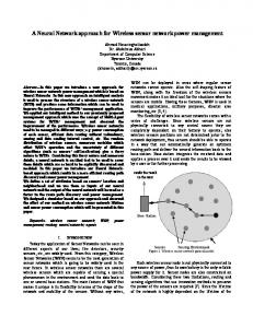
to all wireless applications, it works well for the industrial process control space. A complete test for wireless mesh consists of two parts: a test environment (TE) and the subject under test (SUT). As shown in Figure 1, the SUT can be a single device (SUT 1), a mesh component (SUT 2), or a complete mesh (SUT 3). The TE encompasses everything the SUT interacts with in the test. If the SUT is a device, then the TE will be the mesh network that the SUT lives in; if the SUT is a mesh component, then the TE is the rest of the mesh; if the SUT is a complete mesh, then the TE is all the interferences that can affect the functioning of the mesh. Sometimes it is also desirable to simulate a full mesh running in a real environment. In this case the TE will be a full mesh and the SUT will be absent. In this paper we also use the term DUT (Device Under Test) to name a SUT if the SUT is a single device. A TE can be a controlled environment in house or the uncontrolled real environment in the field. A testbed specifically designed for industrial process control is a TE that is fully under the tester’s control, normally in house. Ideally, a testbed should be able to accurately simulate any environment where a SUT can be deployed. The objective of a testbed is to ensure that the SUT is ready for field deployment. In other words, if the SUT successfully passes all the tests in the testbed, we should be assured that the SUT will function reliably in the field. There are two major tasks with a testbed. One is to model the TE and the other is to simulate the TE and interact with the SUT. Firstly, the testbed should reproduce the environment for the SUT. This includes defining and modeling the real environment in which a SUT will be deployed. For example, the existence of plant equipments has direct impact on the wireless signals in a manufacturing plant. In this case, a wireless plant survey should be conducted and the results fed to the testbed. Secondly, the testbed may interact with the SUT in such a way that the SUT cannot tell the difference between the testbed and the real environment. This paper addresses the second task. We assume that the environment model and parameters are already programmed into the testbed. To a SUT, the TE is a set of networked nodes and a set of interference sources. The latter can also be considered as
SUT3
SUT1
SUT2
Fig. 1. The SUT can be a single device (SUT 1), a mesh component (SUT 2) and a complete mesh (SUT 3).
network nodes that misbehave. The conventional approach in setting up a testbed is to duplicate each node with one in the physical testbed. This approach introduces the following difficulties for a wireless mesh testbed: •
• •
•
Since the nodes communicate through wireless, we have to make sure that the nodes in the testbed are communicating among themselves correctly and reliably. The TE can contain hundreds of nodes and it would be difficult just to set it up before putting the SUT in. It is a challenge to convert a physical node to simulate all interferences. Similarly, it is a challenge to tell a physical node to misbehave in a controlled manner. The approach does not scale. For different types of SUT, the testbed has to be configured and organized differently. It will be costly to maintain different testbeds during different stages of a mesh network development or deployment.
By understanding what really matters to the SUT, we propose a virtual network environment (VE) as the TE. In the testbed the interaction between the VE and the SUT is simplified through simulating multiple physical devices with one transceiver. Our approach has been successfully applied to Wi-HTest [3], a real testbed product for compliance verification that is being used by WirelessHART companies. The remainder of this paper is organized as follows. We explain the virtual network approach and the corresponding wireless mesh testbed in Section II. We describe the detailed design of such a testbed, i.e., Wi-HTest in Section III. Section IV presents a representative example on how the testbed is used and how it relates back to our design philosophy. We conclude the paper in Section V and discuss future work. II. T HE V IRTUAL N ETWORK A PPROACH Given a test scenario, the traditional way to set up a testbed is to deploy exactly the same number of physical devices as needed in the experiment, and to configure each device according to the experimental configuration. In our testbed design, however, we model the TE, including the environment interferences with a virtual network. Our goal is to achieve good scalability by reducing the number of physical devices in the testbed as much as possible, and this is achieved by using the same antenna for multiple purposes. The virtual network is configured in a script that is passed as an input to the testbed.
In this section, we shall present our approach and explain the rationale behind it. Let us first look at the TE and the SUT. We emphasize that the SUT is the entity that we really care about; what is inside the TE is irrelevant as long as it correctly interacts with the SUT in a controlled manner. The TE itself should be controlled and must not fail. So what really matters is the communication between the SUT and the TE. For wireless mesh networks, the SUT interfaces with the environment through and only through its antennae. At the physical level, only one antenna at a time is required for the TE to talk to one antenna of the SUT. This antenna can carry different messages from different network nodes and thus reduce the total number of antennae needed in the TE. Accordingly, we make the following observation: Premise 1: If a wireless mesh uses at most N physical channels at any given time, then a testbed can reproduce a complete TE with only N physical antennae. Note that the set of the N physical channels does not need to be fixed. For N = 2, a mesh may use channels 11 and 12 at one time and channels 13 and 14 at the other time. If a mesh uses only one physical channel then only one antenna is necessary for a full testbed! One example is the ZigBee network. Although a ZigBee network can select any of the 16 channels in the 2.4G spectrum, it is fixed on one upon creation. In theory we can use a single antenna to reproduce in real-time all the messages generated by a ZigBee network in its life time. There are several reasons for reducing the number of antennae in a mesh testbed. Firstly, the antennae in the testbed must coordinate message transmission and reception with one another according to the mesh protocol. Secondly, the testbed must control the messages communicated via the antennae. These goals are difficult to achieve if a testbed has tens of devices and each device has its own antenna. After we have reduced the number of antennae for the testbed, we then look at how to represent the network through these antennae. The virtual network is the network simulated by the testbed but it must not allow the SUT to tell the difference. We note that the major wireless communication standards for industrial process control are all TDMA-based and provide network-wide time synchronization. Each packet transmission or reception is conducted in a dedicated timeslot with a fixed time offset. We take advantage of this accurate timing information in our virtual network approach: whenever a physical device tries to communication with the SUT on channel c at timeslot t, we choose the antenna that represents the same channel and perform the same communication at timeslot t. This makes the SUT believe that it is interacting with a real wireless network. A typical industrial control mesh network is characterized by low power consumption and relatively low data rate, and this helps to make our approach viable. The speed of today’s computers is fast enough for the testbed to simulate all mesh functionalities in real time. For example, the data rate of an IEEE 802.15.4 radio is 250K bits per second. An 1GHz Intel processor can stream out enough data for 40 simultaneous
III. W I -HT EST - A T ESTBED BASED ON V IRTUAL N ETWORKS In the last section we provided the general design idea of a wireless mesh testbed based on virtual networks. Wi-HTest is such a testbed that we have developed. Although it has not realized all the potential of this approach, the current version is sufficiently complete for practical deployment. Wi-HTest is already used and marketed as a component of the WirelessHART certification suite from the HART Foundation [4]. The current Wi-HTest has only one antenna, and yet all but a few test cases in the test specification can be performed with Wi-HTest.
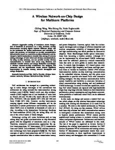
Test Scripts
Virtual Virtual Network Network Manager Manager
Network Network Layer Layer Library Library
Incoming MSG Incoming MSG Processor Processor
Transmit Transmit
Wi-HTest Engine Wi-HTest Engine
Receive Receive
RF Board Communications Driver RF Board Communications Driver
Wi-HTest Host Wi-HTest Host
USB USB
mesh transmissions at the rate of generating 1 bit per 100 CPU cycles. An additional benefit of our approach is easy control of the testbed. With the control of the testbed centralized, we avoid the difficulties and error-proneness of controlling a distributed network of nodes in a testbed. An important issue raised in the last section is scalability. By adopting the idea of virtual network and one antenna per physical channel, we can develop one testbed to serve multiple purposes. The testbed can be used if the SUT is a device, a mesh component, or a complete mesh. To deal with different SUTs, we do not need to change the hardware. Rather we use a different virtual network by changing its configuration. The small size of our Wi-HTest testbed contrasts significantly to what it can perform. Since a testbed is to prepare a SUT for real-world deployment, the environmental interference must also be addressed by the testbed. There are many sources of interference in reality and it is not the goal of this paper to model interference mathematically. Our assumption is that whatever the source of interference, its impact on the SUT is solely on its antennae and that we can use the antennae in the testbed to generate the same impact. For example, we can change the transmit power from the testbed dynamically to simulate a mobile node or temporary blockages. We can also send out a continuous wave on one channel to simulate background noise. We can also deliberately send incorrect messages or drop correct messages to simulate unreliable communications. We consider this to be a realistic assumption for the industrial process automation domain. It is unlikely in our domain that multiple communications simultaneously use the same physical channel since the process control is typically performed in relatively small wireless mesh networks. We conclude this section with the summary of our testbed design using virtual networks: • The testbed hardware consists of a testbed computer and one or more antennae. • The TE is modeled with a virtual network. Different virtual networks are fed to the testbed computer for different test cases. • The computer simulates the virtual network. When a message is to be sent to or received from the SUT, one antenna is selected to communicate at the physical layer, and the message communicated will be composed or parsed in the context of the virtual network. • Environment interference is to be simulated and generated through the antennae.
SUT SUT
Fig. 2.
IEEE802.15.4Radio IEEE802.15.4Radio
RF Board RF Board
Wi-HTest Host Architecture
A. Wi-HTest Architecture Wi-HTest is introduced in [3] as a part of the WirelessHART certification suite and specifies only the basic support for what is needed in the standard conformance test cases. What we have made of Wi-HTest is a far more powerful testbed. To avoid redundancy, we shall not repeat the details of Wi-HTest related to the certification suite. We shall focus on introducing the new features with regard to Wi-HTest as a mesh testbed. We shall emphasize on Wi-HTest’s role in helping development and deployment of WirelessHART devices and networks. Wi-HTest consists of a host computer that controls the network and upper layers, and a RF interface board that controls the physical and data link layers. They are connected via a USB cable, which also supplies power to the RF board. The Wi-HTest host is responsible for overall control and execution of the input test scripts. The architecture of the WiHTest host is depicted in Fig. 2 and it consists of four major modules: the RF board interface driver, network layer library, virtual Network Manager, and the execution engine. • RF Board Interface Driver The driver, including the incoming MSG processor, is the bridge between the WiHTest host and the RF board. It uses a simple private protocol for communication through USB. • The Network Layer Library The network layer is constructed as a library along with an independent receiving thread in the Wi-HTest host. Putting the network layer on the host enables us to realize the virtual network more efficiently on the computer. The test engine uses it to construct outgoing network messages and parse incoming ones. The network layer library provides function calls to construct or manipulate the data payload and packet header while the receiving thread handles the response packet back from the data link layer or processes received unsolicited messages. • The Virtual Network Manager The virtual network manager stores and is responsible for the virtual network configured by the test script. The test engine consults with it to decide when, what, and on which virtual device’s behalf to send instructions to the RF board. The incoming messages are also passed to the virtual network manager for processing.
Wi-HTest Test Engine The heart of the Wi-HTest host is a test engine. An important component of the test engine is the application layer library. It works together with the virtual network manager and the network layer library, and provides a set of supporting functions through the user interface to help testers generate various test scripts. These scripts implement the specific requirements of the test case. This mechanism results in the rapid development of various test cases. The Wi-HTest host talks to the SUT via the RF board. The RF board works on behalf of all the virtual devices. By default it works as an Access Point. The RF board runs a real-time embedded compact stack. It is responsible for low-level, timecritical communications to and from the SUT using its onboard wireless transceiver. Responses from SUT are forwarded back to the Wi-HTest host. •
B. Wi-HTest Functionalities In this subsection we describe how the virtual network is realized with Wi-HTest and what kind of SUT tests can be achieved with Wi-HTest. 1) The Virtual Network: The virtual network is defined by the script and created and managed within the host. The RF board functions on behalf of all virtual devices in the network. It is configured by the host. Any configuration or transmission command from the host to the RF board includes the indication of which virtual device is associated. The host has total control on the radio over when and what to transmit or receive, which the host decides based on the virtual network. In this way, the SUT is tricked to believe that it is operating in a real WirelessHART network with multiple devices. We model environmental interference through the manipulation of the radio. The direct impact of an interference is on the success of message transmission and reception. We can control the RF board to transmit messages at different energy levels, inject errors in the message, or simply transmit continuous noises; we can also decide Wi-HTest not to acknowledge messages from the SUT at the data link layer or the network layer. 2) The Current Capability of Wi-HTest: In theory Wi-HTest can achieve any TE in which there is only one radio active at any given time. In this subsection we list what is available in the current version of Wi-HTest. In the next section we shall show representative executions of Wi-HTest that demonstrate its capabilities. • Virtual Network Support Wi-HTest supports the features described in Section III-B.1. • Transmit Power Manipulation The transmit power of individual virtual device is configurable. This can be used to simulate temporal interference on the communication quality with a virtual device. • Noise Generation The RF radio can, upon request, transmit continuous carrier wave on a certain physical channel. This can be used to simulate a noisy channel. • Packet Manipulation To provide the tester complete control over the transmitted packet, a critical feature provided by the network layer library is the bitwise packet
•
•
manipulation. It allows the testers to change the header and the payload of the packets in every layer. These manipulation functions provide the testers complete control over the packets and help them design a large number of test cases. Clock Skew Manipulation The clock drift on the RF board can be adjusted on the fly. This can be used to test synchronization robustness. The limitation is that all virtual devices must have the same manipulated clock drift. Go Silent The test script can also ask any virtual device to go silent for a period of time. IV. W I -HT EST T ESTBED D EMONSTRATION
There are hundreds of standard test case scripts in WiHTest. Instead of trying to cover all of them, we shall only present a comprehensive test case in this section in which the DUT interacts with a full virtual network that is simulated by Wi-HTest. The usefulness of the virtual network will be demonstrated as we go through the different stages of the test case, which covers several major activities of a WirelessHART mesh network [5]. The messages shown in this section are captured by Wi-Analys [3], a WirelessHART package sniffer tool from the HART Foundation. Wi-Analys is, like Wi-HTest, another component of the WirelessHART device certification suite. Note that to save space, in the captures that follow, many unrelated messages are filtered out and only selected columns are displayed. A. The Test Case In our test case, we have three devices, the access point (AP), the virtual device 1 (VD1), and the virtual device 2 (VD2). VD1 and VD2 are directly connected to the AP. The DUT is allowed to join either through VD1 or VD2. Once joined, the DUT will be configured links to both VD1 and VD2. The test case runs the following steps: 1) The RF board is configured with the virtual network. Both VD1 and VD2 start advertising. 2) The DUT requests join either through VD1 or VD2. 3) The DUT is allowed to join and is configured links to both VD1 and VD2. 4) Commands are routed from the network manger and the Gateway to the DUT, which responses accordingly. 5) The DUT’s burst data request is granted and it starts publishing data periodically. 6) One virtual device is then shut down. The messages from the DUT are no longer acknowledged. 7) The DUT reports “Pathdown Failure” to the Network Manager through the other virtual device. 8) The Network Manager reconfigures the links. The device addresses used in this test case are summarized in Table I. Note in Wi-Analys, the DUT’s address is sometimes replaced by its tag name. The network ID used is 0x1236. B. The Capture of one Execution The test case can run as long as necessary. In one execution we captured 5665 messages with Wi-Analys. In this section we shall highlight some of the Wi-Analys screen captures.
Device Network Manager Gateway Access Point
Address 0xF980 0xF981 0x0001
Device DUT Virtual Device 1 Virtual Device 2
Address 0x0004 0x0005 0x0006
TABLE I Device Addresses
Fig. 4.
Fig. 3.
The DUT Joins the Mesh through the VD2
1) The DUT Joins the Virtual Network: The first thing a device does after power up is to join the mesh. Fig. 3 captures the message segment of the DUT joining the network. Interested readers are referred to [3] for the details of the device join procedure. In this case, the DUT selects device VD2 to join, by sending out join request Packet 499. The join request is forwarded to the AP (Packet 509), who forwards by wire to the Network Manager. Once the join request is validated, the Network Manager then sends out the join response. The join response is sent from the AP to the VD2 (Packet 515), who forwards to the DUT (Packet 521). The join response is actually a write request so the DUT sends out the write response message in Packet 523, which is again forwarded in packet 532. At this point the DUT is considered joined. But it can only talk through the VD2 via the join links defined in the advertisement message. So the next set of commands in Packet 538 is to configure the DUT for normal communication within the mesh. This includes writing superframe (Command 965) and links (Command 967). Note Wi-Analys does not know the network key or session key until it captures Packet 521. As a result it does not understand packets 509 through 516. It deciphers packet 499 because it is preconfigured with the public and join keys. Also note that in Fig. 3 and the rest of the figures all messages are acknowledged by active receivers except advertisement messages. If the link is among the virtual devices, the message and the acknowledgement are both transmitted by the Wi-HTest RF board. 2) Graph Routing and Source Routing: WirelessHART supports graph routing for robustness. A graph is directional
Source Routing and Graph Routing
with only one sink node which is the destination of any message. In graph routing, a message is forwarded by the intermediate nodes to the next neighbor on the graph. Each node is pre-configured with a set of forwarding neighbors of a graph so that it can make the routing decision locally. The data source simply associates a graph with the message and sends it out. In this test case the DUT is configured two graph neighbors, the VD1 and VD2, to send message to the Network Manager and the Gateway. In source routing the path is defined in the message network header. A routing device simply forwards the message to the next device in the path. Fig. 4 shows the last command from the Network Manager and the first command from the Gateway. • Packet 690 to 695 The Network Manager sends Command 64512 to the DUT with source routing, whose list is AP, VD1, and DUT. The message is sent from the AP to the VD1 within the virtual network (Packet 690). The VD1 then forwards to the DUT (Packet 697). • Packet 697 to 703 The DUT sends Command 64512 response back to the Network Manager using graph 0x01C1. The DUT selects the neighbor VD2 (Packet 697), who then forwards to the AP (Packet 702). • Packet 708 to 720 The Gateway sends Command 0 to the DUT using graph 0x01B1. The AP selects the neighbor VD2 (Packet 708), who then forwards to the DUT (Packet 719). • Packet 721 to 726 The DUT sends Command 0 response back to the Gateway using graph 0x01A1. The DUT selects the neighbor VD1 (Packet 721), who then forwards to the AP (Packet 725). Note this time the DUT selects a different neighbor from the previous response to Command 64512. 3) Burst Data Publishing: The main function of a sensor in a process plant is to periodically publish process value to the Host. In this test case the DUT is preconfigured to publish Command 48 every 8 seconds. After the session and links with the Gateway is configured, the DUT sends Command 799 to the Network Manager asking for the information to publish (Packet 895 in Fig. 5, forwarded in Packet 906). Since the Network Manager has already configured for this, it simply replies with the route information in Packet 912 which is
Fig. 5.
The DUT Publishes Command 48
Fig. 7.
Network Reconfiguration
5080 forwarded in Packet 5083). It contains: deleting the graph edge to the VD1 (Command 970), removing two links to the VD1 (Command 968), and adding two extra links to the VD2 (Command 967). The DUT responses in Packet 5086. V.
Fig. 6.
Network Maintenance
forwarded in Packet 917. The DUT then sends out the first burst data in Packet 945, forwarded in Packet 949. About 8 seconds later (Refer to the second column Elapsed Time in Fig. 5) the DUT sends out the next burst data in Packet 971, forwarded in Packet 974. 4) Network Maintenance: WirelessHART defines many ways to keep the mesh network healthy. The device periodically sends health reports to the Network Manager; it also reports to the Network Manager if a neighbor is no longer communicating. In this test case we shut down the VD1 after the DUT has established publishing data. Fig. 6 shows the DUT reporting Command 788 (Path Down Alarm of the VD1) to the Network Manager (Packet 5070 forwarded in Packet 5077). Note that before the report the DUT sends message to the VD1 twice in packets 5062 and 5069, neither of them is acknowledged. Fig. 6 also shows the reporting of Command 780 (Report Neighbor Health List) from the DUT in Packet 5057. It is interesting to see that the VD2 forwarded it (Packet 5066) after it has received a burst data from the DUT (Packet 5063). Fig. 7 shows what happens after Command 788 is received. The Network Manager sends a message to the DUT (Packet
CONCLUSION
In this paper, we presented our design and implementation of a lean yet versatile wireless mesh testbed for the industrial process control domain. We applied a virtual network approach in our testbed where one radio board is used to represent one channel instead of one physical device. This design philosophy greatly reduces the size of the testbed and improves its scalability. Our hybrid approach combines the advantages from both the network simulators and traditional testbeds. It supports multiple physical devices and as many virtual devices as necessary according to the network configuration requirements. All the physical devices and virtual devices work together and form a hybrid network that enables controlled network behaviors and allows experiments to be conducted under realistic network conditions. Our approach has been adopted in Wi-HTest, a major compliance certification suite for WirelessHART devices in industrial process control. We demonstrate our approach by describing a detailed test case. R EFERENCES [1] “WirelessHART,” http://wirelesshart.hartcomm.org/. [2] “ISA100,” www.isa.org/isa100. [3] Song Han, Jianping Song, Xiuming Zhu, A.K. Mok, Deji Chen, M. Nixon, W. Pratt, and V. Gondhalekar, “Wi-HTest: Compliance test suite for diagnosing devices in real-time wirelesshart network,” in Real-Time and Embedded Technology and Applications Symposium, 2009. [4] “Hart communication,” www.hartcomm.org/. [5] Jianping Song, Song Han, A.K. Mok, Deji Chen, M. Lucas, M. Nixon, and W. Pratt, “Wirelesshart: Applying wireless technology in real-time industrial process control,” in Real-Time and Embedded Technology and Applications Symposium, April 2008, pp. 377–386.