Centro Ricerca di Automatic, ENEL. We present a graph-based object model that may be used as a uniform framework for direct manipulation of multimedia ...
A Visual Retrieval Environment for Hypermedia Information Systems DARIO LUCARELIA
and ANTONELlA
Centro Ricerca di Automatic,
ZANZI
ENEL
We present a graph-based object model that may be used as a uniform framework for direct manipulation of multimedia information. After an introduction motivating tbe need for abstraction and structuring mechanisms in hypermedia systems, we introduce the data model and the notion of perspective, a form of data abstraction that acts as a user interface to the system, providing control over the visibility of the objects and their properties. A perspective is defined to include an intension and an extension, The intension is defined in terms of a pattern, a subgraph of the schema graph, and the extension is the set of pattern-matching instances. Perspectives, as well as database schema and instances, are graph structures that can be manipulated in various ways. The resulting uniform approach is well suited to a visual interface. A visual interface for complex information systems provides high semantic power, thus exploiting the semantic expressibility of the underlying data model, while maintaining ease of interaction with the system. In this way, we reach the goal of decreasing cognitive load on the user, with the additional advantage of always maintaining the same interaction style, We present a visual retrieval environment that effectively combines filtering, browsing, and navigation to provide an integrated view of the retrieval problem. Design and implementation issues are outlined for MORE (.Multimedia Object Retrieval Environment), a prototype system relying on tbe proposed model, The focus is on the main user interface functionalities, and actual interaction sessions are presented including schema creation, information loading, and information retrieval. Categories and Subject Descriptors: H.2. 1 [Database Management]: Logical Design—data models:H.3.3 [Information Storage and Retrieval]: Information Search and Retrieval-query ~ormulation; selection process; H.5. 1 [Information Interfaces and Presentation]: Multimedia Information Systems—hypertext nauigatiorr and maps; H,5.2 [Information Interfaces and Presentation]: User Interfaces-interaction styles General Terms: Design, Human Factors, Management Additional Key Words and Phrases: Browsing, complex objects, direct object manipulation, graph-oriented models, hypermedia applications, information filtering, visual interface
This work was supported by the Italian Electrical Energy Company under the research project 0. L.240 Multimedia Systems. Authors’ addresses. D, Lucarella, Centro Ricerca di Automatic, ENEL, Via Volta 1, 1-20093 Cologno Monzese, Milano, Italy and Dipartimento di Scienze dell’Informazione, University degli Studi di Milano, 1-20135 Milano, Italy; email: lucada(Q imicilea.cilea.it; A. Zanzi, Centro Ricerca di Automatic, ENEL, Via Volta 1, 1-20093 Cologno Monzese, Milano, Italy; email: zanzifl cra.enel.it. Permission to make digital/hard copy of part or all of this work for personal or classroom use is granted without fee provided that copies are not made or distributed for profit or commercial advantage, the copyright notice, the title of the publication, and its date appear, and notice is given that copying is by permission of ACM, Inc. To copy otherwise, to republish, to post on servers, or to redistribute to lists, requires prior specific permission and/or a fee. @ 1996 ACM 0734-2047/96/0100-0003 $03.50 ACM Transactions on Information Systems, Vol. 14, No. 1, ,January 1996, Pages 3-29.
4.
D. Lucarella and A. Zanzi
1, INTRODUCTION Hypermedia has been simply defined as a system to manage a collection of information that can be accessed nonsequentially. It consists of units of information that are arbitrarily diverse in form and content. Such units may contain texts, graphics, images, sound, video, and animation and are connected by logical links to form an information network. The variety of nodes and links that can be defined makes hypermedia a very flexible environment in which information is provided both by what is stored in each node and by the way the information nodes are linked to each other. In addition, current hypermedia systems provide sophisticated user interface tools that enable the reader to inspect the node content and to navigate through the network by selecting paths to follow on the basis of interests emerging along the way [Nielsen 1990]. There is a growing interest today in such technologies for the implementation of massive multimedia information systems, but unfortunately, several well-recognized problems continue to be open research issues [Halasz 1988]. Among these, central points to be addressed are information modeling and information retrieval.
1.1 Information Modeling The simplicity of the basic hypermedia model does not appropriately represent the structure of the information. There is an inadequate separation between a node in the hypermedia network and the content associated with the node. Conversely, a strong separation of the structure from the content would allow many structures to be superimposed over the same set of information units or a unit to be shared among many nodes within a single structure. In addition, a node is a storage unit for a collection of data items without any structural information, and each node and link are assumed to be of the same type. As a result, modeling is more or less a bottom-up process in which we have to analyze how information can be broken down into different elements and then to recognize these individual elements by adding links among them. The problem here is that such an analysis is only useful for that particular instance, and we cannot use this same structure for other instances [Tompa 1989]. The key point is that the basic hypermedia data model is too simplistic. It is not suitable for modeling the real world or capturing its semantics as required in most applications [Furuta and Stotts 1990; Garzotto et al. 1993; Schnase et al. 1993a]. As a consequence, the user has dif%culty in perceiving the conceptual model of the application, resulting in cognitive overhead [Conklin 1987]. In authoring mode, extra mental effort is needed to establish the links required to connect the created nodes. In reading mode, extra mental effort is needed for choosing the path to follow through the network, with the risk of becoming lost or disoriented. One of the main ideas proposed by Garg [ 1988] is that information embedded into the hypertext network should be described by a set of predefined ACM Transactions on Information Systsms, Vol. 14, No. 1, January 1996.
Visual Retrieval Environment for Information Systems
.
5
domain objects. In this way, the actual content of the hypertext would be represented by a set of information objects, each of which is an instance of a domain object, inheriting by default all of the properties of the domain object. The idea can be compared to the notion of database schema, as opposed to a specific instance of the database. According to this trend, many hypermedia systems have been proposed with the support of underlying databases [Campbell and Goodman 1988; Christodoulakis et al. 1986; Lange 1990; Schnase et al. 1993b; Schutt and Streitz 1990]. Recently, requirements for representing the structurally complex interrelationships that arise in hypermedia have generated a renewed interest in semantic data models [Hull and King 1987]. Semantic models attempt to provide more powerful abstraction and structuring mechanisms for specifying database schemas in order to overcome the limited modeling capabilities of traditional database systems [Beeri 1990; Lieberherr and Xiao 1993]. Schnase et al. [ 1993a] presented a comparative analysis of semantic models, concluding that a structural object-oriented paradigm appears to be superior for hypermedia modeling. Of particular interest are graph-based data models since they provide a natural way of handling data that appear in applications such as hypermedia or multimedia information systems. Gyssens et al. [ 1990] proposed a graph-oriented object database model in which the database schema as well as the database instances can be seen as graphs with the data manipulation language expressed in terms of graph transformations. Amann and Scholl [1992] presented a graph data model with an associated algebraic language based on regular expressions over the data types and showed how such a language can be exploited for hypertext querying. In the same direction, in this article we propose a graph-based object model which provides high semantic expressibility, and we use it as a uniform framework both for conceptual modeling and for direct manipulation of the stored objects.
1.2 Information Retrieval In hypermedia information systems, interaction is mainly devoted to information retrieval. A canonical approach is based on formal querying [Bertino et al. 1992; Straube and Ozsu 1990]. Conversely, browsing techniques consist of exhaustively viewing part of the information base until the desired information has been found. The former approach requires a deep knowledge about the query language, the conceptual structure of the application, and the goals; the latter does not require a preliminary knowledge. On the other hand, a formal query, if correctly formulated, can be directly evaluated and may yield an immediate answer, whereas a browsing session can take a long time before converging to the goal or may not converge at all. Between these two mentioned interaction techniques, other approaches must be studied with the aim of balancing expressive power and ease of use. Some approaches to the integration of query-based retrieval strategies in a hypertext network have been proposed recently. Logic-based languages have ACM Transactions
on Information
Systems,
Vol. 14, No. 1, January
1996.
6.
D. Lucarella and A. Zanzi
been proposed by Consens and Mendelzon [1989], Lucarella [1990], Afrati and Koutras [1990], and Beeri and Kornatzky [1990]; different attempts to exploit the hypertext links in the retrieval of the relevant nodes have been reported by Croft and Turtle [1989], Lucarella and Zanzi [1993], and Frei and Stieger [1992]. A common aspect to such proposals is that no concept of schema has been introduced, and thus, queries can be specified only over the hypertext network in order to get an optimal starting point for browsing. Conversely, as remarked in the previous section, the approach we are taking in this work is based on a semantic data model, the primary objective being to provide powerful visual constructs for representing a variety of abstractions in a structured fashion. Unfortunately, as soon as the underlying data model becomes more complex, the level of complexity of the associated query language and the level of knowledge required by the user also increase. The main goal becomes the design of a language that provides both high semantic power and ease of interaction with the system. With this objective in mind, we propose a visual query paradigm. The user performs actions symbolically and directly on the screen and is able to express operations by grabbing and manipulating visual representations of objects. The user is not required to know any complex formal language, with the advantage of maintaining the same interaction style normally used during browsing. The effect produced by the query is perceived as a form of filtering and navigation space restriction, So it is natural to pass from querying to browsing and vice versa, depending on the type of user, the type of application, and the type of current needs. By effectively combining browsing and querying under a uniform interface, we provide an integrated view of the retrieval problem. Much research has been carried out in the database community on graphical query languages that has influenced our approach at different levels. Basic principles and a survey of such efforts can be found in C!atarci [1992] and Batini et al. [1992] respectively. Most graphical interfaces are based on intensional data models, typically the entity-relationship model [Angelaccio et al. 1990; Kuntz and Melchert 1989; Wong and Kuo 1982] or the extended entity-relationship model [Auddino et al. 1991; Czejdo et al. 1990]. ISIS [Goldman et al. 1985] and its extension ISIS-V [Davison and Zdonik 1986] provide a visual interface to the semantic data model SDM [Hull and King 1987]. SNAP [Bryce and Hull 1986] is a system based on the IFO data model [Hull and King 1987]. More recently, some projects have dealt with object-oriented data models [Epstein 1990], and DBface provides a tool for building graphical interfaces to object-oriented databases [King and Novak 1993]. The remainder of this article is organized as follows. Section 2 provides a description of the semantic model on which the MORE system is based. This section also includes an example subschema that contains multimedia information about the organization and the activities of our research division. The visual retrieval environment along with the formal definitions of perspective and the operations on perspectives are presented in Section 3. Various examples illustrating the expressive power of the language are presented ACM Transactions on Information Systems, Vol. 14, No. 1, Janusry 1996
Visual Retrieval Environment for Information Systems
.
7
with reference to the example subschema shown in Section 2. Section 4 sketches design issues for the MORE prototype system focusing on the main functionalities and presenting visual interaction screendumps taken from the actual application. Section 5 provides a comparison with related work. Finally, brief conclusions and future research work are outlined in Section 6. 2. A GRAPH-BASED
OBJECT
MODEL
The basis of the approach is the characterization of the information system in terms of objects, attributes, and relationships, namely, a general object-oriented conceptual model. An object is an entity of the real world, a concept, an event, a process, or anything else that an application tries to capture and represent. Objects have their own identity that does not change throughout their lifetime and are known by their properties. The specific set of properties used to describe a given object depends on the point of view and the purpose of the modeling. We recognize properties only through attributes. Objects having the same structural properties are grouped together to form an object class. Classes can be related by a superclass-subclass relationship in which an object in a subclass inherits the structural properties from its superclasses. Object attributes can be divided into two general categories: simple and complex. The domain of a simple attribute is a system-defined basic type; the domain of a complex attribute is a class. At the intensional level, the conceptual schema captures this semantic structure. It is defined by a collection of interrelated classes and types, and as such it can be represented by a directed labeled graph. Objects and classes are related by the instantiation relationship. At the extensional level, the information system can be viewed as a collection of interrelated objects, and as such it can also be represented by a directed labeled graph. Thus, the information system can be represented by graphs at both the intensional and the extensional level. A formal definition of such concepts is given next. 2.1 The Model Definition.
The conceptual
schema
2 is defined as the five-tuple
where: —C is a finite set of class names; each class c E C denotes a structure (in terms of attributes) and an extension (the collection of objects that have that structure). —T is a finite set of type names (e.g., integer, system; each t E T denotes a type of primitive associated values.
text, picture) built into the object, and V(t) is the set of
—A is a finite set of attribute names. Attributes are defined on classes. Attributes may be simple or complex. The domain of a simple attribute is a ACM Transactions
on Information
Systems,
Vol. 14, No. 1. January
1996.
8.
D. Lucarella and A, Zanzi
basic type t ● T; the domain of a complex attribute is a class c e C. In addition, we distinguish between single-valued attributes As and multivalued attributes A., with A = A, U Am. —9 c C x A x (C u T) is the property relationship. If (c,, a, Cj) =9, then the class c, has the attribute a, having as a domain the class or type Cj. —% c C x C is the inheritance partial ordering relationship. If (cl, c, ) ●%, then the class Ci is a subclass of the class Cj inheriting attributes from CJ. Definition. graph
Given
X, the conceptual G(Z)
schema graph
is a directed
labeled
= (iV, E),
where: —N = C U T is the set of nodes. For each c = C, we have a rectangularshaped node labeled c. For each t E T, we have an oval-shaped node labeled t. —E is the set of edges. For each (c,, Cj) = % we have a bold edge connecting Ci to CJ. For each (c,, a, c,) = @ we have an a-labeled edge from Ci to Cj. Particularly, if a = As we have an edge with a single arrow; if a ● Am we have an edge with a double arrow. Definition. tuple
The multimedia
information
M=(X,
system M is defined as the four-
O, Y, P),
where: —2 is the conceptual schema defined above. —O is the set of objects stored into the system. —> c O x C is the instantiation stance of a class c = C. —% c O X that the instance following
relationship.
Each object
o = O is an in-
A X (O U V(T)) is the link relationship. (o,, a, Oj) =9 denotes attribute a of the object Oi has the value Oj. Assuming the o, of c, and the Oj instance of c,, we have (o,, a, o,) ~& iff one of the conditions holde:
(1) (Cl, U,Ci)
G 9;
(2) (c,, Ck) ~ 2?A (ck, a, cj) G 9; (the conditions (3) (cj, c~) ~%’A
(C,, a,ck)
The last two conditions inheritance relationship.
or alternative)
=9.
are the direct consequence
Definition. Given the multimedia graph is a directed labeled graph G(M)
information
of the semantics system
M,
of the
an instance
= (N, E),
where: —N = O U V(T) is the set of nodes. Nodes represent objects nodee) or values (oval nodes) generated from the schema instantiation relationship. ACM Transactions on Information Systems, Vol. 14, No. 1, January 1996.
(rectangular through the
Visual Retrieval Environment for Information Systems
Fig
1,
Graph-based
object model: Intentional
and extensional
.
9
levels
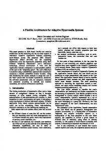
—E is the set of edges. For each (o,, a, o~) = Y’, there is an a-labeled from o, to 0].
edge
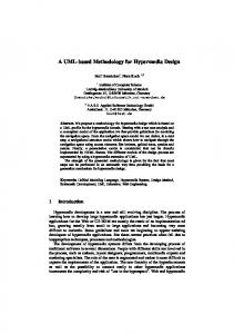
Based on this model, Figure 1 gives an example that shows how we can use a graph-based representation at both the intentional and the extensional levels. Note the effect, at the extensional level, of the inheritance relationship between the class student and the class person. 2.2 A Sample Hypermedia Application In order to demonstrate the capabilities and the flexibility inherent in the approach discussed, a hypermedia application has been developed. The application is aimed at storing multimedia information concerning the structure of the organization and the activities of our research division. It describes the hierarchical structure of the research units, including information about management, personnel, financial budget, research projects, and project leaders. A portion of the schema graph is presented in Figure 2. This schema is used throughout the article as the knowledge base to which all visual operations will be posed. With reference to Figure 2, rectangular nodes in the graph represent classes, and oval nodes represent basic types. Labeled arrows starting from a class depict the properties of that class. Multivalued properties are shown with double-headed arrows. The bold lines express the inheritance is-u relationship from a subclass (at the tail of the arrow) to its superclass. In the following, we describe in further detail the meaning of the objects depicted. Research Unit groups the common attributes (name, direction, ACM Transactions
on Information
Systems,
Vol. 14, No
1, ,January
1996.
10
D. Lucarella and A. Zanzi
.
expmses
1 pmonnr.1 Research
unit
is-a I
is-a
direction
is-a
t+ is-a
Division
Fig. 2. Conceptualschemagraph.
mission, personnel, and expenses) shared by the units at different hierarchical levels. The Research Division represents the administrative and strategic central headquarters to which all of the research centers spread throughout the country report. The Research Center is a department, characterized by a specific research area with its own laboratories. The Laboratory is the operative research unit, with its own equipment, in which the research projects are carried out. The Research Project is characterized by title, subject, description of objectives, project leader, and a short movie presenting its current state with the main results achieved. Note that some research programs are carried out as joint projects, and consequently, a cycle is present in the graph. The Experimental Installation represents an installation characterized by its name and location, where some experiments that cannot be made in the laboratories are carried out in the field. The Person groups the common attributes (name, resume, and photo) shared by the manager and the project leader. The Manager is the head of a research unit: the central division, a research center, or a research laboratory. The Project Leader is a person who is in charge of a research project. Finally, the Employees class gives information about the personnel in a research unit, grouped by category and by age, respectively; and the Budget class represents the financial planning of a unit, both in terms of the estimate of the expenses and of the balance. Note that the conceptual schema of the application is directly entered and manipulated on the screen by the application designer supported by an appropriate visual tool (see Section 4). ACM Transactions
on Information
Systems,
Vol. 14, No. 1, January
1996.
Visual Retrieval Environment for Information Systems
3. VISUAL INFORMATION
.
11
RETRIEVAL
In this section we deal only with the retrieval and presentation issues without considering other functionalities. In addition, a clear distinction between the information user and the information supplier is quite common in these systems, since object loading and updating often require specialized multimedia editors depending on the type of object manipulated. We have already discussed in the introduction the main reasons for developing a visual interface based on the direct-manipulation paradigm and the expected advantages for the end users in terms of abstraction power, ease of interaction, and flexibility. Basic requirements are the visualization of the conceptual schema as well as the database instances, by enabling the user to filter the amount of information to be displayed. Selective information visualization can be used to locate relevant information and to restrict the visualization to the pertinent parts. A reasonable way to present complex information is to produce multiple views of the same information, each focusing on different aspects and thus conforming to different needs. The cognitive overhead required to face tangled information structures can be alleviated if the system presents only the relevant pieces of the stored information while hiding the rest, In analogy with the views in databases, we introduce the notion of perspective, 1 a form of data abstraction that acts as a user interface, providing control over the visibility of the system objects. A perspective can be tailored to focus selectively on the subset of information that is significant to a particular application. Essentially, perspectives are graph structures that are built from the schema graph and are visually manipulated in various ways. Related works on graph-based object manipulation are reported by Andries et al. [ 1992] and Guo et al. [1991]. In the following, we provide formal definitions for perspectives and a basic set of operations that can be performed on perspectives. For each of these in turn, we give the formal definition, the visual expression, and an example referring to the previous application. 3.1 Perspective Defin it ion. Given a multimedia defined as P(rr, S ),where:
information
system,
a perspective
P is
— rr is the perspective pattern, that is, a weakly connected subgraph of the schema graph 2; hence, N( rr) c N(Z) denotes the subset of schema nodes (classes and types) included in the perspective, and E(n) g E(2) denotes the set of edges (properties) associated with such nodes. —S is the set of object graphs generated by the perspective graph T through the instantiation relationship. Given an instance s E S, each node o = N(s) 1The term perspect~[x, has already been introduced by Garzotto et al. [ 1993], hut with a different meaning. 2A directed graph is weakly connected iff the graph obtained by removing the arrowheads is connected ACM Transactions on Information Systems. Vol. 14. No 1. January 1996
12
.
D. Lucarella and A. Zanzi
name
1
Person A
is-a I Research
unit
Research
Center subject
Fig. 3.
A perspective
over the schema.
is an instance of the corresponding node c E IV(w) and the edge ( Oi, a, Oj) = E(s) iff the edge (ci, a,cj) ● E(m). So, a perspective is defined by a pattern (the intensional representation) and by the corresponding object graphs (the extensional representation). In order to define a perspective, the user has to build the pattern into the “perspective window.” The requested nodes are copied from the “schema window” by pointing and clicking. The system checks automatically that the resulting graph is connected. In this way, incorrect perspectives cannot be specified, since the patterns conform to the structure of the schema. In Figure 3 we show a perspective focusing on those parts of the information system in which the user is interested. In the example, attention is restricted to the research centers and their laboratories including, for each of these, the research projects and corresponding project leaders. Perspectives can be named, saved, reused, and manipulated in various ways. In particular, it is possible to define perspectives on perspectives, thereby producing different levels of abstraction. All of the operations on perspectives are closed, thus removing the major drawback of current objectoriented query languages that do not maintain the closure property [Shaw and Zdonik 1990]. Consequently, in our approach, the result of each operation has the same structural properties as the original objects; thus, it can be further processed by the same set of operators. 3.2 Object Filtering In order to restrict attention to a subset of pattern instances tive, a filter can be defined over it. ACM Transactions on Information Systems,
Vol. 14, No. 1, January
1996
in the perspec-
Visual Retrieval Environment for Information Systems
CRA
.
13
Is-a
c>r CRIS
t’
Research Unit
‘r
is-a
-3
Project Leader
string equipment
joint
P
in-char e
M.lumdm
projects
Swwm
subject presentation
description
Fig,4. Filterspecification.
Definition. Given a perspective P(T, S), a filter F is defined in terms of a set of selection conditions {Cl, . . . . Cn) over the pattern. Let a, be an attribute of type t pertaining to a node (class) n, in the pattern m; then C, represents a selection condition over the actual values of the corresponding object instances. The selection condition is a boolean combination A, v , 1 of simple expressions of the form (al e aj ), where al is a type-compatible property or a constant, that is, some value from the domain t; e is a comparison operator depending on the type of the operands. In Figure 4 a filter has been defined over the perspective shown in Figure 3, with selection conditions over two (shadowed) nodes. In particular, this example is the visual expression of the following complex query: “I want to know if, in the research centers named C.R. A. or C. R. 1.S., there are research projects in the field of Multimedia Systems, and if this is the case, I want to see the laboratories where the activities are carried out and the responsible project leaders.” From the user’s point of view, one merely “clicks,” one by one, on the nodes in the pattern over which conditions have to be specified. The clicked node changes its color (shadow in the figure), and a text window is opened to enable the user to enter the requested conditions. As is well known, in case of recursive properties (e.g., “joint” on “Research Project”), a selection condition specified over the class “Research Project” or related ones can have different semantics. We decided to allow a very limited form of recursion in order to guarantee immediate comprehension and ease of formulation, which has been our constant guideline in the design of this system. So the specification of conditions either over the class “Research Project” or over related classes yields the retrieval of projects satisfying the ACM Transactions on Information Systems. Vol. 14. No. 1, January 1996
14
.
D. Lucarella and A. Zanzi
conditions. Then the projects joined to each of them are retrieved. Namely, the condition is intended as a starting condition for the computation of the transitive closure. The effect of a recursive property at the extensional level is shown in the next example. Definition. Given a perspective P(m, S) and a filter F defined over P, a selection operation u returns a subset R c S of pattern instances matching the filter: (rF(P)=
R={
SISESASE
F}.
A pattern instance s matches the filter iff it satisfies all of the conditions A i. ~,. CL; a condition C, over the class i is satisfied ifl it is true for the corresponding object instance values. From the user’s point of view, after having specified the pattern and the filter, it is enough to “click the “select” button. The system notifies the user, resetting the button when (1) the query has been processed and (2) the matching instances have been identified. In this way, it is possible to restrict the attention to a subset of instances according to the conditions specified in the associated filter. From now on, it will be possible to access the single objects belonging to the retrieved set R of pattern instances or to iterate the process by further modifying the perspective. The impression perceived by the user is that a profile is defined denoting the user’s interests; the system filters out useless information; and the user sees what is left. The effect of this filtering capability is to restrict the attention to a manageable subset of nodes. For a discussion on the features qualifying the information retrieval and information-filtering processes, see Belkin and Croft [1992]. In the following example, we show the effect of the selection operation at the extensional level. Assume we have a basic perspective PI focusing on the “Laboratory,” relative “Budget,” and “Research Project” with “Project Leader.” In Figure 5(a), the pattern of the perspective is reported together with the corresponding pattern instances (for simplicity, only rectangular nodes are shown, and link names are not reported). Figure 5(b) presents the instances retained after the definition of the perspective Pz and the execution of a selection operation on the basis of the specified filter. Definition. Two perspectives P1(T1, S1) and Pz(~z, Sz) are said to be compatible when they have the same pattern but different instance sets: Tr~= 7r2; sl # S2. This is the case resulting same original perspective.
from the application
of different
filters to the
3.3 Basic Operations on Perspectives Now we introduce
basic binary operations
to combine
perspectives
together.
Definition. Let Pl(nl, S1 ) and PZ(TZ, Sg ) be two perspectives, with ITl # Vz and N(TI ) n N(T2 ) # O. A composition operation @ over the set of nodes ACM Transactions on Information Systems, Vol. 14, No. 1, January 1996.
Visual Retrieval Environment for Information Systems
.
15
b)
Fig, 5. (a) Pattern and instances on perspective P2.
of perspective
N’ = N(TI ) n N(mz ) generates
PI. (b) Result of the selection operation
the perspective
— r is the composition of the two patterns union of nodes and edges, respectively, = E(7r1) u E(m2); and
defined
P(m, S) = PI @ P2 where:
rl and r2, obtained by taking the N(n) = N(wl ) U N(mz ) and E(T)
—S is the set of instances of the pattern n, obtained by composing the instances in SI with those in Sz; two instances can be composed iff, for all of the nodes (classes) N’ = N(ml ) n N(7Z ), they share the same object instance. Figure 6 gives an example showing the effect at the extensional level of the composition operation. In Figure 6(a), the perspective P~ is shown defining a filter over the “Laboratory,” and then in Figure 6(b) we see the effect of composing P~ with the perspective Pz (Figure 5(b)). Definition. Let PI(T ~, S1) and P2(m2, S2 ) be two compatible perspectives. An overlay operation @ generates the perspective P(7, S) = PI @ Pz, where: —*.=l.
fiz is the pattern; and
—S is the set of instances S={ SISGS1VS=S2).
included
in both of the perspectives,
that is,
This last operation is effective in getting pattern instances satisf~ng a disjunction of conditions. In Figure 7(a) the perspective P4 is shown defining a filter over the “Project Leader,” Next, in Figure 7(b) we see the effect of overlaying P4 on the perspective P~ (Figure 6(a)). The overlay P3 fB P4 ACM Transactions on Information Systems, Vol 14, No. 1, January 1996.
-,
,,,
.-
v. Lucare[la arm A. ~anzl
).
m.
mrEEl I
I
I
4- I project
L1
/
Fig. 6. (a) Perspective operation P2 @ P3.
P.
“
with a filter over the laboratory.
Budget ‘4
(b) Result
of the composition
P3@P4
T’ 171
“ect
7
Fig.
7.
(a) Perspective
P4
“
with a filterover the projectleader.(b) Resultof the overlayoperation
P3 fBP4.
retains the instances in both of the perspectives, thus providing the research projects either managed by the project leader P2 or developed in the laboratory LI. The composition and overlay operations are very useful in combining perspectives together and are simply activated by selecting the appropriate icon button and then by dragging one perspective window upon the other. In general, perspectives might be regarded as layers between the user and the information system. Many perspectives can be available in order to have different views on the same information network, each one focusing on some information and hiding the rest. ACM Transactions
on Information
Systems,
Vol. 14, No. 1, January
1996.
Visual Retrieval Environment for Information Systems
.
17
3.4 Object Access In order to access and view the objects in the instantiation hrcwsing and navigation operations are available.
of the perspective,
Definition, Given a perspective P( rr, S ), let c E N( n-) be a node (class). A hrousing operation A’ returns all of the relative object instances) iff included in one of the pattern instances s E S; A’,(p)=
{olo=.
Y(c) AoG
~(s)}.
Referring to the same example, by “clicking” on the node “Research Center,” we get the content of this information node in the “presentation window.” By default, simple attributes are embedded into the window with layout (e.g., font, color, size) derived from information set up during the loading (see the next section ). Service buttons are then available for moving forward and backward through the list of instances in the case of multiple instances. Conversely, complex attributes are depicted in the window as “icon buttons” that can then be activated in navigation mode. The effect of such operations can be seen in Figure 11 (next section), where a display screendump is shown. Definition, Given a perspective P( n, S ), let o be a displayed object in the instance s E S, and let a be one of its complex attributes. Then a navigation operation [” returns the linked object(s): ,/ .((),(P)
= {o’l(o,
a,o’)=.YAo’=
N(s)}.
Note that the last condition in the definition prevents the user from accessing nodes outside of the perspective. This is achieved dynamically by disabling and masking those buttons pointing to objects out of the perspective. Users may navigate from instance to instance according to their interests by “clicking” on the “icon buttons” representing the links. The navigation operation allows access to the information nodes following direct links into tbe perspective graph. Note that, in case of nodes involved in recursive properties (e.g., “Research Project”), all of the matching instances are returned by the browsing operation, whereas the joined projects can be reached by navigating through the “joint” link. Like many hypermedia systems, it is useful to have a “reverse button” in order to follow reverse links. Given a node, this can be achieved by computing the set of nodes linked to it in the pattern instances. Definition. Given a perspective P( T, S), let o be a displayed object in the instance s E S. A reLwrse navigation operation / ] returns the object(s) linked to o: ,/
‘(p)
,,(, ))
={o/(o’,
a,o)G.
YAo’
GI’V(,S )).
Note that the operation returns all of the nodes pointing to the given one, and it is not intended for going back to the previously visited node. Such a history mechanism can be achieved, if requested, by maintaining a trace of the visited object identifiers. In order to activate the rer,wrse-na[?igation operaA(’M Transaction.
on information
Systems.
\’1,1 1 i, NI) 1, J;inuary
19%
18
.
D. Lucarella and A. Zanzi
tion, the user clicks on the “reverse button” in the presentation window, and the system presents the user with the list of the attribute names pointing to the given node in the perspective pattern. Once the requested one has been selected, the instances of the objects pointing to it are returned. The mechanism we have described in this subsection corresponds to the usual way in which browsing and navigation through the information network are accomplished in current hypermedia systems. The important differences are that (1) on the side of the user, such features are integrated into a uniform interface so that a smooth shift becomes possible from querying to browsing and vice versa and (2) on the side of the system, such features are integrated and implemented using the same query-processing subsystem. 4. THE PROTOTYPE
SYSTEM
“MORE”
Since the focus in this article is on the visual interaction environment, only an overview of the system architecture is provided, emphasizing those useroriented characteristics that have motivated this research project. 4.1 Design Overview There is a general consensus in the field for separating the storage layer from the application and presentation layers by creating a separate object data server [Halasz and Schwartz 1994; Wiil and Leggett 1992]. According to this trend, our system is composed of two cooperating subsystems that communicate via a stream socket with the TCP/IP protocol. Communication is established on a client/server basis, where the subsystem MORE (Multimedia Object Retrieval Environment) [Lucarella et al. 1993] is the client process that requests object retrieval services to the subsystem CORE (Complex Object Representation Environment). This is a knowledge-based management system under development as a joint effort between ENEL and the University of Milan. An outline of the system architecture is given in Figure 8. At present, CORE includes an efficient object management system that is aligned to the requirements of the prototype implementation. In the future, it will be substantially extended to become an intelligent multimedia object server. The knowledge representation and manipulation language is based on a tight integration between the object-oriented and logic programming paradigm, and it is able to manage and query complex multimedia objects. Essentially, we use a semantic object model as a conceptual front-end to the CORE-like object base. As a possible alternative, cooperation with available commercial object-oriented databases may be taken into account in the future. The MORE system supports schema creation and manipulation, information loading and formatting, in addition to information filtering, browsing, and navigation. The MORE environment takes advantage of the powerful semantic model upon which it is based and stresses, above all, ease of comprehension and ease of use [Lucarella et al. 1994]. The main features ACM Transactions
on Information
Systems,
Vol. 14, No. 1, January
1996.
Visual Retrieval Environment for Information Systems
P user
:
R
schema Editor
)
r
: ,
Processor
‘“e
19
reusability,
and
s e m a n t i c
MORE Fig. 8.
characterizing consistency:
Manager
;:
[ Pteaent. data
schema& Pmpcct.
s
Le ir
.
the interaction
System architecture
environment
are flexibility,
—Flexibility. Users differ from each other in terms of level of experience with the task and in terms of frequency of use of the task. Our interface is powerful and flexible enough to adapt to different situations. Graph-based information representation and icon-based manipulation are attractive for novices, but as shown before, also enable expert users to express complex selection and filtering criteria. —Reusability. Users are allowed to reuse definitions of objects already known to the system. This is useful both in the schema design, in order to allow incremental schema definition, and in the retrieval environment. In particular, evaluated perspectives can be saved with reference to a specific information demand and reused later, either in the same way or modified to build a new similar perspective. —Consistency. Special care has been taken to use consistent modes of operation and the same interaction style when passing from one function to another. The underlying semantic model provides a base for this consistency. All operations are based on the same schema representation, and the same graph-based manipulation paradigm is used in interacting with the various system functions during both the design and operation phases. The MORE system runs on IBM RISC/6000 workstations under the AIX Operating System and AIXwindows. It has been developed by exploiting the usual OSF/MOTIF facilities, such as icons, palettes, buttons, dialog boxes, etc., and consists of the visual tools presented in the following subsections. 4.2
Editing Environment
The schema editor enables the application designer to create a schema graph or to edit a previously created one, by picking icons from a predefine palette, positioning and manipulating them directly into the associated window ACM Transactions
on Information
Systems,
Vol
14, N{,. 1, .January
1996
20
.
D. Lucarella and A. Zanzi
P
data
GSb.11’g
-1
\ [
%S,ls
l--%-l--
9 W!9
Fig. 9.
Editing environment.
workspace. As shown in Figure 9, a limited number of icons in the palette is sufficient to denote the actions that can be performed upon the primitive components of the model. Depending on the icon selected, default actions are activated, and/or an appropriate text entry window is presented. The creation of a class requires the user to pick up the rectangular icon from the palette, to position it in the workspace, and then to enter the class name, with the system checking for the uniqueness of the name. In case of primitive types, the oval icon is picked up and positioned, with the system proposing a choice of built-in types. The same procedure is used for the properties. The user picks up the icon corresponding to the desired property, clicks on the nodes involved in the relationship, and then enters the label. The sequence by which the nodes are touched affects the direction of the link. It is possible and easy to affect the graphical layout of the schema by dragging and moving around the objects afl.er their initial positioning or by anchoring the graph and stretching or shrinking it. The deletion of nodes and edges, regardless of the type, is achieved by picking up the respective icon and then by clicking on the node/edge to be removed. Note that the deletion of a rectangular node is achieved only if no incoming edges are present, and when petiormed, it automatically implies the deletion of all outgoing edges along with the oval nodes pointed to by such edges. ACM Transactions
on Information
Systems,
Vol. 14, No. 1, January
1996.
Visual Retrieval Environment for Information Systems
.
21
When saving the schema, validation functions are activated to check whether the actual schema definition is consistent with the syntactic rules of the model, thus preventing possible mistakes. If inconsistencies are detected, they are graphically emphasized so that the user can easily identify the problem and correct the schema accordingly. Clearly, the visualization of the schema graph by the editor is limited by the physical size of the screen. This may cause parts of the graph to be offscreen, affecting the perception of the overall structure when the schema increases in size. Presently, usual techniques including panning, zooming, and scrolling are implemented; in the future the introduction of hierarchical graphical abstractions will be considered, as suggeeted by Paulisch [1993], to alleviate this problem. 4.3 Loading and Formatthg
Environment
Once the load environment has been activated, and the desired schema has been selected, the schema is presented to the user in a read-only window. It is now possible, given a class, to load the object instances or to enter the formatting specifications that will affect the presentation of all of the objects belonging to that class. The instance loader, activated through the corresponding icon, enables the loading/updating of object instances according to the associated schema. The user identities the object class by clicking on it, and an appropriate template is presented in order to enter the values of the attributes for that instance, with the system checking for type consistency, If a multivalued attribute is present, two buttons are reported on the right that allow either the scanning of the values already entered or the entry of new values. Obviously, it is possible to have many loading templates at the same time on the screen, and each template is equipped with back and forward buttons to inspect the already loaded instances. In particular, this is useful when managing complex attributes since, in this case, it is necessary to load the object identifier of the referenced object. That can be easily achieved by displaying in another template the object to be referenced (already loaded) and then by dragging its identifier to the appropriate attribute slot. When the template has been filled in, the object can be loaded, and the template can be cleared for further loading. Validation checks are activated in this phase. The format manager enables the entry of formatting specifications. A box is associated with each class containing other boxes for each of the attributes of the class. By clicking on a specific class, the associated box is presented by default. It is now possible to interact for the definition of the layout (1) by dragging and moving each box to the appropriate position and (2) by stretching each box to the appropriate size (this is also true for the outer box). At the same time, it is possible to define the font to be used in case of string/text attributes and the colors for the background/ fore~ound of the box. The same facilities are available for the buttons associated with the links (complex attributes) and with the labels of the attributes. In this phase, the box of the attribute value is distinguished from the box of the attribute label by the ACM Transactions
on Information
Systems,
Vol, 14, No. 1, January
1996
22
.
D. Lucareila and A. Zanzi
Fig. 10. Loadingandformattingenvironment.
presence of a star on the right of the string. Note that these specifications are interpreted as layout constraints for attribute types that require special processing (e.g., pictures, formatted documents, movies). To give a better idea of such capabilities, an example of user-machine interaction is given in Figure 10, referring to the object class “Manager.” 4,4 Retrieval and Presentation Environment The retrieval enuirorzrnerzt provides the user with direct-manipulation facilities for defining and operating on perspectives, as presented above. In the retrieval environment, the user can directly access the object instances or, conversely, can define a perspective in order to focus only on relevant information. Such information can be filtered either to get optimal starting points for navigation or to restrict the attention to a manageable subset of objects. Once entered into the environment, the selected schema graph is displayed in a read-only window. The perspective is built inta the perspective window by a sequence of “point-and-click actions on the classes in the schema graph. The designated classes are copied into the perspective window together with their attributes having as a domain primitive types. Namely, all oval nodes pointed to by the designated node are copied by default. A click on an edge ACM Transactions on Information Systems, Vol. 14, No. 1, January
1996.
Visual Retrieval Environment for Information Systems
.
23
will copy the participating classes, always with the same rule for the attributes. If necessary, the user may later pick up additional nodes or remove some of them. Once the user has built the desired perspective into the perspective window, she or he proceeds with the specification of the filter. After clicking on the class and relative attribute to be filtered, the required conditions can be entered by using a corresponding text box presented by the system. After the filter is defined, a click on the select icon activates the function. Unlike other interfaces in which the results of a query are returned in a form inconsistent with the query, here the user gets the results as instances of the perspective, thus maintaining the abstraction level provided by the model. The presentation environment enables the user to display the object instances. Simple attribute values are embedded into the presentation window according to their formatting specification, whereas complex ones are represented by buttons with the label of that attribute. These buttons allow the display of the instances of complex attributes through navigation. The presentation tool can be activated either on a perspective or directly on the schema graph. In the latter case, all of the instances associated with a class will be displayed one-by-one without any filtering performed by the perspective. With reference to the application described previously, Figure 11 shows the status of the display after a sequence of select and browsing operations. The bottom “schema window” shows the conceptual schema graph; in the “perspective window,” a filter has been specified corresponding to the request “find the research projects dealing with the subject uisual languages and developed at the laboratory named LINT.” Then, after clicking on the “Research Project,” we see in the presentation window the first of the selected instances, formatted according to the loaded specifications. It should be clear now that all possible operations can be performed symbolically and directly on the screen. The user does not need to know either the syntax of the operations or which operation can be applied to which objects. Thus, we reach the goal of decreasing the level of knowledge required by the user, with the advantage of always maintaining the same uniform interaction style.
5. RELATED WORK In this section we briefly present related systems with emphasis on significant differences between each of them and our system. In contrast to the larger number of papers referenced in the introduction, here we focus our attention on three systems that (1) have been proposed in the context of hypertext/hypermedia applications and (2) are centered on a graph-based data model and, hence, exhibit some features that overlap those of MORE. GraphLog [Consens and Mendelzon 1990] is a logic-based query language relying on a graph representation of data whose expressive power has been proven to be equivalent to stratified linear DataLog. The further evolution, the I-Iy system [Consens and Mendelzon 1993], improves the data repreACM Transactions
on Information
Systems,
Vol
14. No. 1. .January
1996
24
s
D. Lucarella and A. Zanzi
Y P31-
-49.
-’L
41
.w--
Fig. 11.
Retrieval and presentation
environment
sentation by using hygraphs and provides a user interface with extensive support for the visualization of large and tangled graph structures. Even considering the more structured representation offered by the hygraphs, the main difference with our system is that no concept of schema has been introduced. Thus, no abstraction mechanism is available in the sense we have introduced, such as types, generalization, complex objects, etc. As a consequence, in GraphLog, queries can be specified only over the instance level, but not over the schema level. In conclusion, the basic assumptions are different, since they attack the problem of tangled structures by improving the selection and visualization tools, whereas we try to overcome the problem by improving the conceptual modeling capabilities. GOOD [Gyssens et al. 1990] is an object-oriented database model in which the schema as well as the instance of an object database is represented by a graph, and the data manipulation is expressed by graph transformations [Andries et al. 1992]. This transformation language has a graphical syntax and semantics and contains basic operations for graph manipulations: addition/deletion of nodes/edges and abstraction, for grouping objects, according to some of their properties. Essentially, the reported papers focus on theoretiACM Transactions on Information Systems, Vol. 14, No. 1, January 1996
Visual Retrieval Environment for Information Systems
.
25
cal issues with the main objective of setting up a framework for the implementation of a general-purpose data manipulation language. Only foundations are discussed without proposing any visual interaction language so that a comparison is difficult to be carried out. Conversely, our work is more retrieval-oriented with the main purpose to make available a visual end-user interface. In addition, our language is centered on the notion of perspective, and the operations available for manipulating the perspectives, filtering, and accessing the information have been strongly influenced by the requirement of being really easy to use. Gram [Amann and Scholl 1992] presents a graph-based model and query language. The model is strongly typed, and a concept of schema has been introduced; but there is no object orientation, in the sense we have introduced, since nodes and edges are simply data types. Regular expressions over the types of the nodes and edge labels are used to qualify walks (an alternating sequence of nodes and edges) in a graph. Central to the language is the concept of )1.yperuwlk, a set of walks in the database graph sharing some nodes, and defined by a hyperwalk expression. Hyperwalks might be considered close to our concept of pattern, but really they are different, since patterns are subgraphs of the schema graph, whereas hyperwalks are linear structures defined by regular expressions. Working on hyperwalks, Amann and Scholl propose an algebraic query language, not yet implemented, that, in our opinion, is not well suited for a visual interface. Conversely, it should be noted that the Gram language, as well as GraphLog, is more expressive than our visual language, which, at the moment, can be shown to be equivalent to first-order logic plus transitive closure.
6. CONCLUSIONS A very important problem in future large multimedia systems will be to provide mechanisms that will allow the user to locate the desired information efficiently and effectively. Extensions of the known technologies for databases, information retrieval, and hypermedia will have to present a common model able to accommodate the semantically rich structure of information, as required in current hypermedia applications. In this article we have presented a graph-based object model that has been used as a uniform framework for visual information retrieval. These concepts have been demonstrated in the implementation of the MORE prototype system, which has been extensively tested in the context of a significant hypermedia application. The considerations developed and experiments carried out in a real setting suggest that the combination of a graph-based object model with the direct-manipulation paradigm provides great flexibility for conceptual modeling, as well as for the effective retrieval of multimedia information. The visual interface is easy but powerful and flexible enough to be suitable for different kinds of users, in terms of experience with the system (naive vs. expert users) or in terms of frequency of use (casual vs. regular users). The system has been proposed to a sample of different users with A~M Transactions on Information Systems, Vol. 14, No 1, January 1996
26
.
D. Lucarella and A, Zanzi
previous experience with Query-by-Example systems as well as with hypermedia systems, and MORE has been fairly accepted by all. In particular, the same reported application had been previously implemented using a widespread commercial hypermedia system. Despite being initially well accepted, essentially due to the easy interaction style, the system created many problems because of the lack of selectivity in information access. With respect to such users, MORE has represented a substantial improvement. The concept of perspective has been easily understood. It has proven to be very powerful and has been exploited also at the system management level for delivering different parts of the information system to different groups of users. In conclusion, although a research prototype, MORE shows considerable promise as an advanced information retrieval environment, in our opinion. Presently, the integration of advanced text-based retrieval techniques under the same visual interface is in progress. As is well known from research in the field, text retrieval is an inherently imprecise process [Salton 1989]. Very often, users are looking for information they do not know, so the request becomes diflicult to formulate in terms of a rigid and unnatural boolean notation. Furthermore, it is not effective simply to partition the set of objects into objects that match the request and objects that do not, without making any assessment of their presumed relevance to the needs of the user [Guardalben and Lucarella 1993]. A considerable improvement can be achieved by enabling users to exploit the notion of perspective and filter in constraining the search space and to enter, in correspondence with text-type objects, a content profile reflecting their own interests. The result will be that, during the filter specification, when clicking on a text attribute, the user is allowed to enter a natural language excerpt, describing in a rough way the interested subject. When processing a request involving text-based filtering, the system applies a best-match search strategy in order to locate the satisfying object instances [Lucarella 19881. Best-match searching involves the identification of the objects that are most similar to the submitted profile, with similarity being measured by an appropriate closeness function. Retrieved object instances are assigned a relevance score reflecting the degree of resemblance to the user’s profile. So, during a following browsing operation, they can be ranked and presented to the user in decreasing order of presumed relevance. Obviously, such relevance scores affect the overall relevance of the patterns in which text-type objects are included. We plan in the long term to extend the functionalities discussed for text-type objects to image-type objects as well. In the same way, during filter specification, in correspondence with an image attribute, users should be allowed to sketch in a visual way the main shape of the image they are interested in, with the system returning the retrieved object instances ranked in decreasing order of relevance. Our previous experiments have not been completely satisfactory [DelBimbo and Lucarella 1991], but the results reported by other authors seem to be promising [Hirata et al. 1993]. ACM Transactions on Information Systems, Vol. 14, No. 1, January 1996.
Visual Retrieval Environment for Information Systems
.
27
ACKNOWLEDGMENTS
This work has been benefited by the efforts of many people. In particular, thanks are due to Cristina Raspollini from the IBM Research Center in Rome for the support given in the frame of a cooperation agreement; Aurelio Lanparone and Stefania Costantini from the Information Science Department of the University of Milan for their research activity on logic-based modeling; Stefano Parisotto and Mauro Zanzi from the same university for the research and programming efforts carried out during the development of their doctoral theses; and John Leggett from the Computer Science Department of Texas A & M University for his suggestions concerning an early version of this article that gave us the chance to improve the system and the article.
REFERENCES .4FRATI, F. mm KOUTRAS, D. 1990, A hypertext model supporting query mechanisms. In Hypertext: Concepts, Systems, and Applications, A. Rizk, N, Streitz, and J. Andr&, Eds. Cambridge University Press, Cambridge, Mass., 52-66, AMAXN, B. ANDSCHOI.L,M. 1992. Gram: A graph data model and query language. In Proceedings of the ACM Conference on Hypertext (Milan, Italy). ACM, New York, 201 –211. ANDRJES,M., GIIMIS,M., PAREDAENS,J., THYSSENSI., AfSDV,m DENBUSSCHE,J. 1992. Concepts for graph-oriented object manipulation, In Aduances in Database Technology, A. Pirotte, C, Delobel, and G, Gottlab, Eds. Lecture Notes in Computer Science, vol. 580. Spnnger-Verlag, Berlin, 21-38, .Mw;~:[AvcR~, M., CATAR(’I. T., AIVUS.WTUWI, G, 1990. QBD*: .4 graphical query language with recursion. IEEE Trans. Softw. Eng. 16, 10, 1150-1163, Aron]xo, A., AMI~L, E., ANOBH.W;AVA, B. 1991. Experiences with SUPER, a database visual environment. In Proceedings of the 2nd International Conference on Database and Expert Systems. Springer-Verlag, Berlin, 172-178. BAT[~[, C., CA~AR(’1, T., COSTAIMLE,M. F., AND LEVIALDI,S, 1992. Visual query systems: A taxonomy. In Visual Database Systems 11, E, Knuth and L. M. Wagner, Eds. North-Holland, Amsterdam, 153-168. BwR], C. 1990. A formal approach to object-oriented databases, IEEE Data Knowl, Eng. 5, 4, 353-382. BEER], C, AhW KOR~A’IXKY, Y, 1990. A logical query language for hypertext systems. In Hypertext: Concepts, Sy.$tems, and Applications, A. Rizk, N. Streitz and J. Andre, Eds. Cambridge University Press, Cambridge, Mass,, 67-80. BELKIN, N. J, AND CROFT, W. B, 1992. Information filtering and information retrieval: Two sides of the same coin? Commun, ACM 35, 12 (Dec.), 29-38. BFRTIM)) E., NWRI, M., PWWATTI, G., AND .’%ATTELLA, L. 1992. Object-oriented query languages: The notion and the issues, IEEE Data Knowl. Eng, 4, 3, 223-237. BRYrK, D, ANDHL’LL, R. 1986. SNAP: A graphics-based schema manager. In Proceedings of the IEEE Conference on Data Engineering (Los Angeles, Calif.). IEEE, New York, 151-164. CmPRix,L, B. AND GOOOMAN,J, 1988. HAM: A general purpose hypertext abstract machine. Commun. ACM 13, 7 (July), 856-861, CATARCT,T. 1992. On the expressive power of graphical query languages. In Visual Database Systems 11, E. Knuth and L. M. Wagner, Eds, North-Holland, Amsterdam, 411-421, CHRJSTOLXJJLAKIS, S., THEOnORJIXXl,M,, Ho, F., PAPA, M., ,om PATHRJA,A. 1986. Multimedia document presentation, information extraction, and document formation in MINOS. ACM Trans. Off. Inf. S.yst. 4, 4, 345-383. CoNswIM B. 1987. Hypertext: An introduction and survey. IEEE thnpu~. 20, 19, 17-41. Co~Sh:~s, M. P, .mn MENDELZON,A. 1993. Hy +: A hygraph-based query and visualization system. In Proceedings of the ACM SIGMOD Conference (Washington, D.C. ). ACM, New York, 511 516. ACM Transactions on Information Systems, Vol. 14, No 1, January 1996.
28
.
D. Lucarella and A. Zanzi
CONSENS, M. P. AND MENDELZON,A. O. 1989. Expressing structural hypertext queries in GraphLog. In Proceedings ACM Conference on Hypertext (Pittsburgh,Pa.). ACM, New York,
269-292. CONSENS, M, P. AND MENDELZON,A. O. 1990. GraphLog: A visual formalism for real life recursion.In Prcweedings of the ACM Symposium on Principles of Database Systems (Nash-
ville, Term,).ACM, New York, 404-416. CROm, W. B. AND TURTLE, H. 1989. A retrieval model for incorporating hypertext links. In Proceedings of the ACM Conference on Hypertext (Pittsburgh,Pa.).ACM, New York, 213-224. CZEJDO,B., EMBLEY, D., ELMASRI,R., ANDRUSINKIEWICZ,M. 1990. Agraphical data manipulationlanguage foranextended entity-relationshipmodel. IEEE Comput. 23,3,26-36. DAVISON, J. W. AND ZDONIK, S. B. 1986. A visual interface for a database with version management. ACM Trans. Off. Inf. Syst. 4,3,226-256. DELBIMBO,A. ANDLUCARELLA,D. 1991. Afuzzyobject retrieval system forimage understanding. In Proceedings of the IEEE Conference on Computers and Communications (Scottsdale, Ariz.).IEEE,New York, 835-841. EPSTEIN, R. P. 1990. Graphical query languages for object oriented data models. In Proceedings of the ZEEE Workshop on Visual Languages (Skokie, 111.),IEEE, New York, 36–41. FREI, H. P. ANDSTIEGER,D. 1992, Making use of hypertext links when retrieving information. In Proceedings of the ACM Conference on Hypertext (Milan, Italy). ACM, New York, 102-111. FURUTA, R. AND STO’TTS,P. D. 1990. A functional meta-structure for hypertext models and systems. Electron. Publ. 3, 4, 179–205. GARG, P. K. 1988. Abstraction mechanisms in hypertext. Commun. ACM 31,7 (July), 862-879. GARZOTTO,F., PAOLINLP., AND SCHWABE,D. 1993. HDM—A model-based approach to hypertext application design. ACM Trans. Znf. Syst. 11, 1, 1-26. GOLDMAN,K. J., KANNELLAKIS,P. C., GOLDMAN,S. A., ANDZDONtK,S. B. 1985. ISIS: Interface for a semanticinformationsystem.In Proceedings of ACM SIGMOD (Austin, Tex.). ACM, New York, 328-342, GUARDALBEN,G. ANDLUCARELLA,D. 1993. Information retrieval using fuzzy reasoning. IEEE Data Knowl. Eng. 10, L 29-44. GUO, M. S., SU, S. Y. W., AND LAM, H. 1991. AD association algebra for processing object oriented databases. In Proceedings of the IEEE Conference on Data Engimering (Kobe, Japan). IEEE, New York, 23-33. object database GYSSENS, M., PAREDAENS,J,, AND VAN GUCHT, D. 1990. A graph-oriented model. In Proceedings of the ACM Symposium on Principles of Database Systems (Nashville, Term.). ACM, New York, 417-424. HALASZ, F. G. 1988, Reflections on Notecards: Seven issues for the next generation of hypermedia systems. Commun. ACM 31, 7 (July), 836–852. HALASZ,F. G. ANDSCHWARTZ,M. 1994. The Dexter hypertext reference model. Commun.ACM 37, 2 (Feb.), 30-39. HIRATA, K., HARA, Y., SHIBATA, N., AND HIRABAYASHI,F. 1993. Media-based navigation for hypermedia systems. In Proceedings of the ACM Conference on Hypertext (Seattle, Wash.). ACM, New York, 159-173. HULL, R. ANDKING, R. 1987. Semantic database modeling Survey, applications, and research issues. ACM Comput. Surv. 19, 3, 201–260. KING, R. ANDNOVAK, M. 1993. Designing database interfaces with DBface. ACM Trans. Inf. Syst. 11, 2, 105-132. KUNTZ, M. ANDMELCHERT,R, 1989. Pasta-3’s graphical query language: Direct manipulation, cooperative queries, full expressive power. In Proceedings of the 5th International Conference on Very .krge Databases (Amsterdam, The Netherlands). VLDB Endowment, Saratoga, Calif., 97-105. LANGE, D. 1990. A formal model for hypertext. In Proceedings of the Hypertext Standardization Workshop (Gaithersburg, Md.). NIST, Washington, D.C., 145-166. LIEBERHERR,K. AND XMO, C. 1993. Formal foundations for object-oriented data modeling. IEEE Trans. Knowl. Data Eng. 5, 3, 462-478. LUCARELLA,D. 1988, A document retrieval system based on nearest neighbour searching. J. Inf. Sci. 14, 1, 25-33. ACM Transactions on Information Systems, Vol. 14, No. 1, Jsnuary
1996.
Visual Retrieval Environment for Information Systems
.
29
L(WAWWLA. D, 1990. A model for hypertext-based information retrieval. In Hypertext: Concepts, S,vsfems, and Applications, A, Rizk, N, Streitz, and J. Andr+, Eds. Cambridge University Press. ~ambridge, Mass., 81-94, L[(AKELLA, D. ANDZAWZ[, A. 1993. Information retrieval from hypertext: An approach using plausible inference. Inf. %ocess. Manage, 29, 3, 299-312 I,t’(’~IwI.I.~, D., PARISOITO.S,, AND ZANZI, A. 1993. MORE: Multimedia Object Retrieval Environment. In Proceedings of ~he ACM Conference on Hypertext (Seattle, Wash.). ACM, New York, 39-50. L(I(-AtW[.i.A, D.. Z~NzI, A., AW) ZAW, M. 1994. A visual environment for multimedia object retrieval. In Proceedings of the ACM SIGCHI Conference on Adcanced Vi.suol Interfaces (Bari, Italy) ACM, New York, 210-212, NIELSEN,,J. 1990. Hypertext and Hypermedia. Academic Press, San Diego, Calif, PArl.M’F;. F. N. 1993. The Design of an Extendible Graph Editor. Lectures Notes in Computer Science. Vol. 704. Springer-Verlag, Berlin. SALTON,G. 1989. Automatic Text Processing. Addison-Wesley, Reading, .Mass. SCHN.ASE, tJ. L.. LIWGETT, J. J., HICKS, D. L., A~U SZAIR), R. L. 1993a. Semantic data modeling of hypermedia associations. ACM Trans. Inf. Syst. z 1, 1,27-50. SCH~ASE, J. L.. LEGGEIT, J. J., HICKS, D. L., NI-XRNBERG,P. J., AND SANcH~z, J. A. 1993b. Design and implementation of the HB1 hyperbase management system. Electron. Puhl. 6, 1, 35-63. SCHCTTT, H. A. ANI) STREITL,N. 1990. Hyperbase: A hypermedia engine based on a relational database management system. Jn Hypertext: Concepts, Systems, and Applications, A. Rizk, N. Streitz, and J. Andre, Eds. Cambridge University Press, Cambridge, Mass., 95-108. SHAW, G. M. AND ZIXNIK, S. B. 1990, A query algebra for object-oriented databases. In Proceedings af the 6th International Conference on Data Engineering (Las Angeles, Calif.). IEEE, New York, 154-162. STRALW, D. D. AND Ozst, M. T, 1990. Queries and query processing in object-oriented database systems, ACM Trans. Inf. Syst. 8, 4, 387-430. TOMPA. F. W. 1989, A data model for flexible hypertext database systems. ACM Trans. Inf. Syst. 7, 1, 85 100. WIII,, U. K. AXI) LEXX:ETT,J. J.
1992. Hyperform: Using extensibility to develop dynamic, open and distributed hypertext systems. In Proceedings of the ACM Conference on Hypertext (Milan, Jtaly). AC.M, New York, 251-261. Wo!w, H. K. T. .ANO K((), J. 1982, GUIDE: Graphical User Interface for Database Exploration. In Proceedings of the 8th International Conference on Very Large Databases (Mexico City, Mexico). VLDB Endowment, Saratoga, Calif., 22-32. Received April 1994; accepted October 1994
ACM Transactions
on Information
Systems,
Vol. 14, No, 1, January
1996