A Workflow-driven Design of Web Information Systems Peter Barna1
Flavius Frasincar2
Technische Universiteit Eindhoven1 Department of Mathematics and Computer Science 5600 MB, Eindhoven, the Netherlands
Erasmus University of Rotterdam2 Faculty of Economics PO Box 1738 3000 DR, Rotterdam, the Netherlands
p.barna;
[email protected]
[email protected]
ABSTRACT The World Wide Web is a rapidly growing business environment hosting a large number of business transactions. Methods for designing Web Information Systems (WIS) have adopted process models, typically as extensions of the navigation models they are based on. We observe that the structure of business processes in WIS goes beyond the scope of the navigation structure and deserves to be a more prominent aspect of the design, abstracted from the navigation specification. This paper explains the design of WIS driven by the specification of business processes of WIS that is used for the automatic generation of models describing the application logic including the navigation structure. The specification of processes is explained on a conference review and submission system and the generation process is demonstrated on the Hera application model.
Categories and Subject Descriptors H.1.m [Models and Principles]: Miscellaneous; D.2.10 [Software Engineering]: Design; H.5.3 [Information Interfaces and Presentation]: Group and Organization Interfaces—Web-based interaction
General Terms Design
Keywords Process-driven design, Web-based Information Systems, Navigation
1.
INTRODUCTION
The World Wide Web has become not only the most important source of information and the largest communication platform, but also a rapidly growing business environment hosting a large number of business transactions. One of consequences is that the web interface is becoming the key gateway for participants involved in complex business processes. The traditional data and navigation-driven models are not suitable for capturing these processes, because they often go beyond the scope of (only) navigation structure. Web interfaces used by a WIS specified in a navigaCopyright is held by the author/owner(s). ICWE’06, July 11-14, 2006, Palo Alto, California, USA. ACM 1-59593-352-2/06/0007.
Geert-Jan Houben1,3
Vrije Universiteit Brussel3 Computer Science - WISE Pleinlaan 2 1050 Brussels, Belgium
[email protected]
tion model reflect the participation of users in the business process from their point of view, but do not explicitly capture the whole business process itself. For example, in a submission system tasks of reviewers and authors are different but both can be specified in an appropriate navigation model. Nevertheless, this model does not explicitly define the overall submission processing, but only sequences of actions taken by author, reviewer, etc. Missing explicit specification of the business process makes the navigation-based design and maintenance of a WIS with a complex application logic difficult. Consider, for example, a requirement changing the submission process in the existing submission system based on a navigation model. The redesign of this system would be cumbersome because the aspect that needs to be changed can be only indirectly implied from the navigation structure. Existing methods for designing Web Information Systems (WIS) are typically data and navigation-driven, but they adopt process models in some way. Let us briefly discuss how the process models are adopted in few representative methods for WIS design. The approach described in [1] uses Business Process Modelling Notation (BPMN) graphical language for expressing process models and it is adapted to be used in WebML [2]. The process modeling phase is one of the first design phases and the navigation model is built afterwards based on the process model. The process and navigation design should be integrated according to [5] by authors of UWE and OO-H object-oriented methods. A skeleton of the navigation structure can be semiautomatically generated from the process model. Another object-oriented process modeling technique described in [6] introduces new modeling primitives (activity nodes associated with navigation classes) in the context and navigation models of OOHDM method [7]. WSDM [8] is an audiencedriven method, where in the first design phase the task hierarchy is built using concurrent task trees and in the second phase the skeleton of navigation structure is generated. As it follows from the previous text, some authors consider computer-aided generation of navigation models from process models. In this paper we propose a specification method and a procedure for automatic generation of a target model from a workflow model. The workflow model describes the business process in the system and the collaboration with users and external systems. A concrete target model defines the application logic of WIS including its basic navigation structure derivable from the workflow model. For the purpose of workflow modelling we have adopted UML
use case and activity diagrams and extended them with a language for detailed specification of activity states. Our approach is explained using a conference submission system example and it is demonstrated on the Hera [4] application model as the target model. The details about the workflow modeling are explained in Section 2, and the principles of its transformation to Hera application model are described in Section 3. Section 4 concludes the paper and suggests future work.
2.
Conference System Make Submission
Author Assign Reviewer
Make Review
MODELS FOR WORKFLOW-DRIVEN DESIGN
UML offers a variety of diagrams aimed to capture dynamic properties of the designed system. Use case diagrams contain high-level description of tasks and their relationships with stakeholders (actors) of the system. Actors represent different toes of users or external systems. Activity diagrams (AD) describe the business process of a system collaborating with actors, where activity states can be distributed to tasks of actors. AD use a small set of modeling constructs and allow the description of distributed and parallel processes. Their inherit some good properties from theoretically wellfounded models (Petri Nets) and combine them with easy understanding and popularity. Besides this, with small restrictions the semantics of AD is formalized in [3]. For AD aimed for WIS design we require that every task of all actors defined in use cases (task model) must be specified in workflow(s) - it must have a swim-lane in the AD describing the WIS. Workflows can be described by ECA rules. We propose a representation of ECA rules describing workflows that allow the detailed specification of activity activities itself. The main advantage of the method described here is that this wrokflow specification allows to define fully functional (web) applications at the level of the workflow model. Hence, such specifications can be used for automatic generation of working web applications. Some object-oriented methods include workflow-driven design support with subsequent automated generation of application skeletons that needs to be manually refined to be functional (e.g. due to limitations of expressiveness of object-oriented models). On the other side, the workflow specification described in this paper can be for instance automatically transformed to a set of Hera models that can be immediately deployed and used (but also can be fine-tuned before the deployment). AD are a good means of graphical representation expressing the synchronization of activities. Therefore AD can be used for generation of the bodies of the ECA rules in the proposed abstract syntax. The generated rules are then enriched with detail descriptions of activities. This detailed description distinguishes few elementary types of activities providing the presenting information to users, gathering information from users, and updating information. A fully defined set of rules is still describing a workflow rather then a web application using a concrete design method and thus it can be used for generation of target models (or source codes). The phases of the process-driven WIS design are: • Identification of actors/roles representing user groups or external systems and their tasks by means of task model (TM) depicted as a use case diagram. • Specification of the application domain data structure in the form of domain model (DM).
Evaluate Paper
PC member
Reviewer
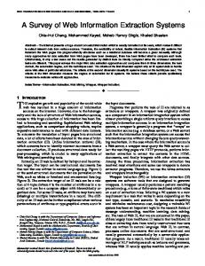
Figure 1: Task model • Specification of overall workflow of the system (or set of workflows) partitioned to tasks in the workflow model (WM). • Specification of the activity states. • Automatic transformation of WM and TM into a target model describing the internal data processing and (basic) navigation structure of the designed WIS. • Eventual fine-tuning of the target models or sources.
2.1
Conference Submission System Example
The workflow model and design concepts are demonstrated on a conference submission system example. The system should register authors, receive a submission from authors, and provide submission evaluation consisting of assigning reviewers by PC members, receiving reviews, and receiving final evaluations from PC members. We assume that reviewers and PC members are already registered in the system. The goal of the system we model is to provide every submission with proper evaluation process.
2.2
Task Model
The functional specification of the system is determined by (business) goals that must be met. These goals can be decomposed to tasks that are performed by actor’s in cooperation with the system. The system has also reserved task(s). We consider the system-centric business process model, where tasks of actors contain only activities providing interaction with the system process. In the initial workflow model actors can communicate directly, but this model is automatically transformed into the system-centric model. The mapping of tasks and actors is stored in the task model (TM) graphically represented as a use case diagram. shown for the submission system example in Figure 1. Definition 2.1 (Task Model). A task model of the system S is the tuple TM (S) =< A, T, α, tS >, where: • A is a set of roles (actors) interacting with the system, • T is a set of task belonging to the roles from A, • α ⊆ A × T is a relation determining the mapping of actors to task specifications, and • tS is a the system task, The use case diagram with aforementioned restrictions can be easily mapped into TM from Definition 2.1.
2.3
Domain Model
Person
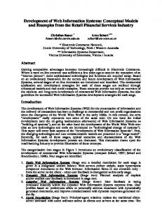
The domain contains concepts representing data structures required by the simple conference submission system. It contains concepts representing submissions, evaluations, actors, and conference details. The main concept is Paper, users (actors) are divided to (Author, Reviewer, and PCMember ) concepts, the evaluation part is represented by Review and Evaluation, and the general conference information is expressed by Conference and Track concepts. Figure 2 shows UML representation of the domain model.
2.4
Workflow Model
A worklfow model (WM) describes processes in the system and collaboration (and communication) of the system and actors. In this section we explain the ECA rule representation of WM with detailed specification of activities. WM is partitioned into task reserved to actors defined in TM. Considered workflow models can be at the high level (without detailed specification of activities) represented by AD and they have Labelled Transition System (LTS) semantics that is often used for describing reactive systems (systems that react to stimuli provided by the environment modelled by actors). The described workflows contain also the mapping of activity states to tasks. Definition 2.2 (Workflow). The workflow F is a LTS represented by the tuple W =< S, E, G, →, S0 , St , Ts , T, τ >, where: • S is a set of all activity states in W , • E is a set of transition labels (events) in W , • G is a set of boolean expressions (guards), • →⊆ S × S × E × G is a set of transition relations triggered by events from E if guarding statements from G (set of boolean expressions) are satisfied, • S0 , St ⊆ S are sets of initial, respectively terminal states, • Ts is a (set of ) system tasks(s), • T is a set of non-system (actor’s) tasks, and • τ ⊆ S × (Ts ∪ T ) is a set of relations mapping states to tasks. This definition determines the structure of workflow models composed from states, transitions labelled by events, and guarding expressions allowing to model decision blocks. It includes also mapping of states to tasks. Workflows conforming Definition 2.2 can be graphically represented using AD, as the submission system workflow shown in Figure 3. This workflow represents (a part of) the submission life span from the moment of it submitting until its evaluation. We consider only the following constructs in AD: initial and terminal states depicted as circles, activity states depicted as ovals, wait blocks depicted as ovals and the label “wait”, f orks and joins depicted as black rectangles, and decisions and merges depicted as diamonds. Lines with arrows denote transitions and labelled rectangles represent data passed as transition parameters. Sequences of states placed between fork-join blocks represent parallel execution branches, and state sequences placed between decision-merge blocks represent optional execution branches selected in runtime based
string: firstName string: lastName string: affiliation string: cid
Author
Reviewer
1..* written_ by
made_by
wrote 1..*
1..* all
Review
1..* hasPC
assigned_by
prepared_by
makes 1..*
Paper string: title file: content
PCMember
assigns
string: text 0..* 1..* of_paper
1..* has_reviews
accepted evaluated_in
in_eval
Evaluation
for
prepares 1..*
integer: mark
Conference
Track string: tname string: tdescription
1..* has_tracks
date: subDeadline date: notifDeadline string: cname
Figure 2: Domain model on the evaluation of guarding conditions. The workflow describing the submission processing is modelled by the AD in Figure 3. It is also possible to have composed activity states that are represented by separate workflows (not in the example). In this case the activity can be unfolded by replacing the activity state with its detailed workflow. WM can be naturally represented by sets of ECA rules in the form e[g] → a, where the action a is triggered by the event e of the guarding condition g is satisfied. For the further explanation the following shortcut notation is used: Transition e[g] from one activity to another will be denoted as a − −−−− → b. For expressing workflows using ECA rules we need to introduce composed events (expressions containing events and synchronization operators) of the following types: • Joined event constructed using the join operator (,) are of the form e1 , e2 , ..., en and take place after all events e1 , ..., en take place regardless order. • Sequenced event constructed using the sequence operator (;) are of the form e1 ; e2 , ...; en and take place when all events e1 , ..., en take place in the order their are written. • Merged event constructed using the merge operator (|) are of the form e1 |e2 |...|en and take place when at least one of events e1 , ..., en takes place. Figure 4 shows how the basic workflow elements are expressed using ECA rules. Rules are in the abstract syntax expressed in the following template: RULE = { PARAMETERS { } ACTION { }
}
The block contains the specification of triggering (eventually composite) events with guarding conditions. The single event with its guard is denoted as
Author/ MakeSubmission
System/ SubmissionFlow
PCMember / AssignReviewer
PCMember / Evaluate
Reviewer/ MakeReview
a1
e Enter Author Login Enter Submission
a2
Store Author
loginfo
WAIT
mauthor
WAIT
submission [submission.date >Conference.subDeadline
e1 a
e2
]
a1 a2
e1 [true], e2 [true]
→
a
e[g1 ]
→
a1
[g1]
a1
[g2]
a2
e[g2 ]
→
a2
a
e1 [true]|e2 [true]
→
a
e1 [true]; e2 [true]
→
a
e View Ackn
→ →
] [submission.date 1 RETRIEVE { PATH { {REV}{dm:Evaluation} {dm:Review AS REVS}} WHERE{ REV = r.review } SELECT{ count(REVS) AS c } } }
PARAMETERS { p = s.submission | r.submission } ACTION { ViewSubmission( p ) } }
3.
GENERATING A TARGET MODEL
In this section we explain the automatic generation of target models from WM. As the example target model we choose the Hera application model (further only AM). Note that a single instance of AM (running web application) can implement multiple instances of the specified workflow running at the same time. For example, in the submission system, a PC member within the activity state V iewSubmission implemented as an instance of a navigation node defined in AM would like to see all new submissions representing multiple workflow instances rather then just one at the same time. Another issue to consider is implementation of correct activity synchronization (expressed by the composed events). It would be too optimistic to assume that the target modelling method would take care about these issues automatically. For this reason the target model implements both issues. The generation of target models consists from the following steps: • Generating data manipulation facilities from the system task(s) rules. • Adding auxiliary data structures and appropriate data manipulation facilities that allow the mapping of multiple workflow instances to a single AM instance and that resolve composite events. • Partitioning the actors’ tasks to clusters of activity states that can be performed without waiting for actions of different actors. This allows the generation of proper (offering tasks that can be accomplished during a single session) navigation structure. • Generating the proper (default) navigation structure from the clustered actors’ tasks.
3.1
Generating Data Processing Facilities
The data processing includes all data manipulation operations, decisions, and activity synchronization. In WM it is represented by a set of information update ECA rules that communicate with user activities through events.
3.1.1
Auxiliary Data Processing Facilities
Let us call messages the events that are sent by the system to the actors tasks (labelling the transitions from system activity states to actors activity states) and back. It is an appropriate name, because these messages are exchanged between the system and its environment, and they often carry information. This information is presented to users or it is entered by users. Most of user tasks (or their parts) represent the transformation of incoming messages to outgoing ones, where some additional information (a value in business terms) is added. For example, a PC member receives a submission information, adds assignments of reviewers to it, and sends it back to the system. Note that these messages are asynchronous, because (human or external system) recipients might not be using the system at the time messages are sent. Furthermore, since there are possibly multiple instances of the workflow running at the same time (e.g. multiple submissions are processed), also multiple instances of the
System / SubmissionFlow
PCMember / AssignReview
SubmissionCl3 message queue
Submission Submission Submission
View Submission / Assign Reviews
Assignments Cl3 message queue
Cluster 3
Assignments
Event
Role
wf_inst MQueue
queue
Message
The operations are transformed into CDM data retrieval and manipulation facilities (in Hera AM to SeRQL queries). For handling the following events the described queries are added to Hera AM: • The system sends a message M to a user (his AM instance). A query providing the operation put(Q, M ) for every generated queue is added to AM.
Figure 5: Message queues for multiple workflow instances DMConcept
• boolean : empty(queue : Q, user : U ) check if the queue Q contains some messages for the user U
User
user
0..* messages parameters
0..*
• A user logs in. Two user identification queries are added, one for detecting if the user is registered using f ind(U ), and another for registering the user via register(U, R). In addition, queries checking the content of message queues (for waiting unprocessed messages) are added. This checking is done for every user when he logs in. The queries implement the functionality of the empty(Q, U ) and get(Q, U ) operations.
Parameter
Figure 6: Context Data Model same type of messages can be sent. This classical problem of asynchronous communication is obviously solved by using message queues automatically maintained by the workflow system (Hera web server according to specifications in generated AM). We assume that the target modelling method (including Hera) does not automatically support the asynchronous communication and message queues. Therefore all needed facilities (context data structures and appropriate data manipulations) are generated. An example of the message queues from our example WM is shown in Figure 5. The context data model (CDM) determines the structure of information needed for user identification, workflow instance identification, and message queueing. The context data is a persistent and updatable. The simplified structure of CDM is in Figure 6. There are multiple M essage and M Queue classes generated according to the workflow structure - for every message one. The detailed structure of P arameter is also based on the structure of event parameters from the workflow specification. Queue classes are singletons and M essage instances are determined by AM instances maintained at runtime. The instances of a workflow are determined by instances of a concept from DM, in the case of the submission system it is the P aper concept. For explaining the facilities added to the target model (AM) the following abstract operations working with users, messages, and message queues are used: • boolean : f ind(user : U ) finds out if the user U is registered. The user can be identified based on is name password, etc. • register(user : U, role : R) registers a new user • msg : get(queue : Q, user : U ) returns a first appropriate (matching a concrete user U ) message from a queue and at the same time removes the event from the queue • put(queue : Q, msg : In) inserts a message In to the queue
• A user logs out. In this case two sets of queries are added to AM. The first set is generated for all incoming (from the point of view of users) message queue that puts messages associated with unfinished activity clusters by put(QIn , MIn ) back to the queues. The second set of queries is generated for all outgoing queues representing finished activity clusters that are put into an appropriate outgoing queue put(QOut , MOut ). As it follows from the previous explanation the state of every workflow instance (implemented as an AM instance in Hera) is given by the content of message queues where the system puts its messages. If all queues where the system puts messages are empty, the system is not waiting for any message from users and then there is no running workflow instance (or it is only under system control). The exceptions are user messages that initiate a new workflow instance, in the case of the submission system it is the loginf o messages from the Author role.
3.2
Generating Navigation Structure
The navigation structure mimics the structure of tasks of all possible actors (and thus is adapted in the runtime based on the role of the logged user). However often the tasks of different actors are mutually dependent. For instance when a PC member wants to evaluate a submission, he/she needs to wait for reviewers to finish the reviews. To prevent possible unlimited waiting for another users during navigation sessions, tasks presented by the web interface are partitioned to activity clusters (AC) that can be accomplished independently of another users. Moreover, the web interface (based on the state of message queues) allows to access only task clusters that are available. The default structure of generated AM shown in Figure 7 contains the login unit (slice), a menu allowing personalized access to AC for concrete users, and a set of navigation structures (navigation clusters) representing AC itself. AC are in Figure 3 shown as gray ovals in swim-lanes, and they are formally explained in Section 3.2.1. AC are mapped into navigation clusters (groups of navigation units (slices) explained in details in Section 3.2.2. Figure 7 shows the default navigation structure generated from workflow specifications. Access to navigation clusters representing AC is determined by conditions attached to menu items corresponding to particular clusters. The conditions check the
3.2.2
Actor
login
fname sname role Login
NOT empty( QNCluster1 , U) NOT empty( QNClusterN , U)
Menu
Role1
...
RoleN
NavCluster1
...
NavClusterN Menu
Navigation ClusterN
Menu
Navigation Cluster1
Figure 7: The default navigation structure generated from a workflow message queues if they contain any new messages representing new particular tasks as it has been explained previously.
3.2.1
Partitioning Tasks
Tasks are partitioned to maximal possible clusters of activities that are not dependent on activities of another actors. For formal definition of AC we need to introduce the event ordering based on the sequence in which events can occur. Definition 3.1 (Event Order). Let F be a workflow as it is specified in Definition 2.2 with the set of events E. The relation £ : E × E determines the order of events in the course of execution. For two subsequent events epre , esucc ∈ E holds: epre £ esucc ↔ ∃1 ≤ i < n, ai ∈ S, ei ∈ E : ei ai − −−− − → ai+1 where e1 = epre , en−1 = esucc It can be shown that the relation £ is a partial order of the set E (it is reflexive, antisymmetric, and transitive). If for a particular workflow model two events are in the order e1 £e2 then in any workflow instance of this model e1 occurs before e2 . Note that not all pairs of events in a workflow must be in this relation (partial order). Partitioning actor’s tasks to AC uses the notion of event ordering. Definition 3.2 (Activity Cluster). Let TA (a) = {s|∃t : (s, t) ∈ τ ∧ (a, t) ∈ α} be a set of activity states in tasks of a single actor a for a task model < A, T, α, tS > and a task workflow < S, E, G, →, S0 , St , Ts , T, τ >. Activity cluster is a set of activity states C ⊆ S such that ∀a, b, c ∈ ← − → → C, − a £ b £− c −→ a, b, c ∈ {TA (a) ∪ TA (system)}. Definition 3.2 says that an AC is a set of activity states, where any three states in the cluster that must be performed in an order must be performed by the same actor, or the system. This property ensures that no activity state in a cluster of an actor follow after an activity state of another actor. This means that performing activities in a cluster is independent on collaboration with another actors. The clustering procedure traverses the workflow structure for activities for all tasks and tries to detect maximal (largest possible satisfying the property from Definition 3.2) AC. The resulting clusters for the submission system workflow are shown in Figure 3 as grey ovals.
Generating Navigation Clusters
Navigation clusters (NC) are navigation counterparts of AC (they implement AC using the Web interface). The internal structure of NC mimics the sequences of activity states in corresponding AC. Information observation activities are realized as slices (in Hera slices represent navigation nodes or their parts, for more details see [4]) presenting data, information entry activities are realized as Hera forms, and information updates as data manipulation queries (Hera extension of SeRQL queries). There are possibly multiple (heuristic) strategies to achieve reasonable results for automated generation of NC. The default strategy is based on one-to-one mapping of information observation activities to navigation units (slices), where information entry forms are integrated with predecessor information observation slices. Concretely, the strategy is based on the following integration rules: • Integration of subsequent information observation and information entry activities to one unit (slice) based on the common fact that information entry usually follows after information observation (user first must have some information to decide). It can be done for a1 ∈ AO , a2 ∈ AE ∧ a1 → a2 , where AO is a set of all information observation activity states within the same task, and AE is a set of all information entry activity states within the same task, and • Integration of subsequent information entry states to one unit (slice) can be done for ∀ai ∈ AE , ai → ai+1 and can be restricted by a maximal number of inputs. The first integration rule would be used for clusters 3,4, and 5 from Figure 3. Because of the lack of space we show only AC “Cluster 3” transformed to the navigation unit Cluster3 depicted in Figure 8 using the Hera AM graphical notation. The V iewSubmission activity is transformed to the Cluster3 slice with the P aper.AssignRevF orm slice presenting all new papers (submissions). They are stored as parameters of messages in the queue SubmissionCl3 (see Figure 5). The abstract operator get() for retrieving messages from queues is implemented as the retrieval query of the slice P aper.AssignRev and removal query RemoveSubCl3 triggered when the Cluster3 slice is instantiated (it removes retrieved messages from the queue). The EnterAssignments activity is transformed into the Reviewer form. Assignmetns is a service query that puts all papers in the list that have not yet assigned reviewers back to the SubmissionCl3 queue and puts the Assignment message with the filled form instance as a parameter into the AssignmentsCl3 message queue (see Figure 5). It also triggers another processing represented by subsequent queries (StoreAssignemnt, etc.). The N avP anel form contains a button for logging of triggering the logof f Cluster3 query is a service query described in Section 3.1.1 for logging off. The following SeRQL query is generated as the retrieval query of the P aper.AssignRev slice: SELECT P FROM {SubmissionCl3}{M}, {M}{U}, {M}{P}, {U}{uid} WHERE uid=$user
The $user is a session parameter representing the current (logged in) user, and the P variable stores the paper instance that is the message parameter.
Paper RemoveSubCl3 ptitle written_by SET
Author
Reviewer iSN lastName
firstName
Assignments
lastName
AssignRev Nav _Panel
logoff _Cluster3
Cluster3
Figure 8: The example NU representing an AC (“Cluster 3”)
4.
CONCLUSION
The contribution of this paper is twofold: it describes a language for detailed specification of workflows modelling business processes of WIS, and it explains the automated generation of a target model describing the application logic of the WIS. Although we briefly show this generation process for a Hera-compliant AM, we believe that it is possible to build programs implementing the generation procedure for arbitrary modeling methods, or directly generate source code for any (programming) language implementing web applications. In our current work we particular considered the extension of other forms of communication with actors than the web interface, including communicating with external systems using web services. Moreover, we think it would be beneficial to build a visual tool facilitating the construction of WM and steering the generation process, possibly for different target models.
5.
REFERENCES
[1] Brambilla, M. and Ceri, S. and Fraternali, P.: Process Modeling in Web Applications, ACM Transactions on Software Engineering and Methodology (TOSEM),(2006)
[2] Ceri, S. and Fraternali, P. and Bongio, A.”: Web Modeling Language (WebML): a modeling language for designing Web sites, 9th International Conference on the World Wide Web (WWW9), Amsterdam”, (2000) [3] Eshuis, H.: Semantics and Verification of UML Activity Diagrams for Workflow Modelling, PhD thesis, CTIT PhD Thesis series, (2002) [4] Houben, G.-J. and Frasincar, F. and Barna, P. and Vdovjak, R.: Modeling User Input and Hypermedia Dynamics in Hera, ICWE 2004, International Conference on Web Engineering, (2004) [5] Koch, N. and Kraus, A. and Cachero, C. and Melia, S.: Integration of business processes in Web application models, Journal of Web Engineering,pages 22-49, volume 3, (2004) [6] Rossi, G. and Schmid, H. and Lyardet, F.: Engineering business processes in web applications: Modeling and navigation issues, Third International Workshop on Web-Oriented Software Technology, (2003) [7] Schwabe, D., Rossi, G., Barbosa, S.D.J.: Systematic Hypermedia Application Design with OOHDM, Hypertext ’96, The Seventh ACM Conference on Hypertext, (1996) [8] Troyer, O.D. and Casteleyn, S.: Modeling complex processes for Web applications using WSDM, Third International Workshop on Web-Oriented Software Technology, (2003)