ZBP: A Zone-based Broadcasting Protocol for Wireless Sensor Networks Chih-Yung Chang, Kuei-Ping Shih
Shih-Chieh Lee
Dept. of Computer Science and Information Engineering, Tamkang University Tamsui, Taipei, Taiwan
[email protected]
Dept. of Computer Science and Information Engineering, Tamkang University Tamsui, Taipei, Taiwan
[email protected]
Abstract—Wireless Sensor Networks (WSNs) have been widely used in motoring and collecting interests of environment information. Packet flooding or broadcasting is essential function for establishing a communication path from sink node to a region of sensor nodes. However, flooding operation consumes power and bandwidth resources and raises the packet collision and contention problems, which reduce the success rate of packet transmissions and consume energy. This article proposes an efficient broadcasting protocol to reduce the number of sensor nodes that forward the query request, hence improves the packet delivery rate and saves bandwidth and power consumptions. Sensor node that received the query request will dynamically transfers the coordinate system according to the zone-ID of source node and determines whether it would forward the request or not in a distributed manner. Compared with traditional flooding operation, experimental results show that the proposed zone-based broadcasting protocol decreases the bandwidth and power consumptions, reduces the packet collisions, and achieves high success rate of packet broadcasting. Keywords- Sensor network; protocol; zone-based; flooding; broadcasting; packet collision.
I. INTRODUCTION Recent rapid advances in scientific and technological progress have created small size, low-power, low-cost, multifunctional miniature sensor devices with sensing, computing, and wireless communication capabilities. These sensor nodes collaborate among themselves to establish a Wireless Sensor Network (WSN), which has been widely used for various applications, including armaments defense, location tracking, widespread environmental sampling, and monitoring health, natural habitats, remote ecosystems, forest fires, disaster sites, and so on. A WSN is composed of a sink node and a large number of sensor nodes that are densely deployed in the particular area. The sink node is a control center which typically initiates a request demand for collecting information from a specific region and analyzes the collected information. Linked by a wireless medium, the sensor nodes perform distributed sensing tasks and transmit the sensed information to sink node or a particular region of sensor nodes respectively in user-demand and event driven manners. Recently, several protocols have been developed for WSN. The main concerns of related study could be classified into two categories, namely sensing and communication. A number of protocols [1] have been developed to maintain the sensing accuracy for special applications, such as location tracking and fault-tolerance. Some researches develop communication protocols [2] for providing WSN with multi-hop data communication services.
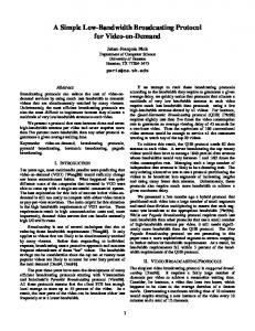
The communicative behaviors in WSNs can be characterized by two different types: routing (node-to-sink) and broadcasting (sink-to-node or node-to-node). Broadcasting is an essential communication requirement for sink and sensor nodes. A sink node usually floods the query request to a region of all sensor nodes in a user-demand manner, asking these nodes for returning environment information. Such an application in WSNs requires a broadcasting protocol to deliver the query information from sink node to all sensor nodes in the specified region. In developing broadcasting protocol, alleviating the packet collision phenomenon will improve the packet delivery rate, which determines whether or not the sensor node will return the sensed information to sink node and thus control the accuracy for a query request. In addition, selecting proper sensor nodes to execute the broadcasting operation will not only alleviate packet collision phenomenon but also save the bandwidth and power consumptions, making contribution to both transmission delay and network lifetime. Hence, developing an efficient broadcasting protocol to avoid collision and contention problems is important for WSNs. Packet flooding is the general technique for broadcasting a message over Ad Hoc networks or WSNs. Most protocols [5] proposed in previous research require to broadcast a message by each node. As shown in Fig. 1, the source host initiates a flooding request to the entire network. On receiving the packet, each node rebroadcasts the packet to its neighbors so that the packet could be delivered to all nodes in network. Although flooding is simple and common used for constructing a communication path in protocols developed for MANET or WSNs, however, it consumes bandwidth resource
Source Sensor Node Collision Phenomenon within two hops The packet forwarding direction within one hop The packet forwarding direction within two hops Figure 1: Flooding operation will create packet collision.
relay the request packets between cells. Although the gridbased or cellular-based management largely reduce the number of nodes executing the flooding operation, however, all managers participating flooding operations also creates the packet collision phenomenon.
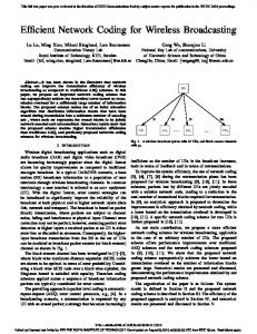
(a) Each cell has unique ID in (b) The relation of coordinate of CBM system. neighboring cells. Figure 2: Coordinate system of CBM[6]
h
b
a
c g Sensor Node
e
d
f
Collision
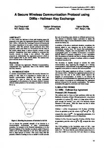
(a) Collision caused by node-level flooding.
M4 M2
M3 M6
h
b
a
c g
e f
d
The rest of this study is organized as follow. Section 2 illustrates the backgrounds and basic concepts of the proposed broadcasting protocol. The efficient broadcasting protocol is proposed in Section 3. Meanwhile, Section 4 proposes the performance evaluation of the proposed broadcasting protocol. Conclusions are finally made in Section 5. II. BACKGROUNDS AND BASIC CONCEPTS This section first reviews the Cellular-Based Management protocol and discusses the collision problem, then presents the basic concept of the Zone-Based broadcasting protocol.
M1
M5
To reduce the cost of broadcasting and alleviate the packet collision phenomenon, this article presents an efficient broadcasting protocol for transmitting a packet from source to a region of all sensor nodes in a WSN. The source could be considered as the first sensor node that receives the query request from sink node and is located in the specified region. Based on the Cellular-Based Management [7], the proposed zone-based broadcasting protocol selects a set of managers and schedules the transmitting delay for the selected managers to alleviate the packet collision phenomenon. Compared with the traditional flooding operations, experimental results show that the proposed broadcasting protocol reduces the bandwidth and power consumption, avoids the packet collisions, and achieves high success rate of packet delivery.
e Manager Sensor Node Collision
(b) Collision caused by zone-level flooding. Figure 3: The impact of node-level and zone-level flooding.
and creates packet collision and contention problems, which reduce the success rate of packet delivery [4]. Ni and Tseng [4] pointed out the negative effect of broadcast operation and proposed various protocols to reduce the packet collision. Stojmenovic etc. [6] proposed techniques to vote some nodes as intermediate, inter-gateway, or gateway nodes to perform the packet transmission and discussed the success rate of broadcasting. To further reduce the number of flooding packets, many location aware protocols [3] partition the MANET into several grids or cells. Nodes in each partitioned cell will vote for a manager to manage the cell, with the manager being responsible for controlling message exchange with the managers of neighboring cells. Hosts wishing to establish a communication path should first send a request packet to their manager, and the manager will then relay the packet to neighboring managers in a flooding manner until the manager of the destination node is found. The extent of packet transmission is thus significantly reduced since only managers
To reduce the number of nodes that transmit the request message in WSN, the Cellular-Based Management (CBM) [7] is adopted herein. The CBM geographically partitions the entire network region into several disjoint and equally sized cellular zones. Figure 2(a) illustrates the partitioned network region. Each cell is assigned a unique Cell-ID, as shown in Fig. 2(a). Figure 2(b) presents the relationship between the Cell-ID of two neighboring zones. The CBM model allows the manager to communicate directly with neighboring managers. The node can identify which cell it is located in. In each cell, the node that is geographically near the center of this zone will play the manager role for executing the information exchange. Whenever a member node desires to establish a communication path, it sends a request to the manager and the manager of each cell then takes responsibility for setting up the communication path. The extent of packet flooding is thus significantly reduced since only managers relay the packet between cells. Although CBM protocol largely reduces the number of nodes that transmit the flooding packet, however, all managers transmitting the flooding packet also creates packet collision phenomenon. Figure 3 shows the comparisons and their impact of node-level flooding and manager-level flooding. In Fig. 3(a), sensor node a broadcasts a message to neighbors b, c, e, g, and h. On receiving the message, nodes b, c, e, g, and h broadcast the received message at the same time, causing packet collision at nodes d and f. Since sensor nodes d and f do not receive the request packet, they will not transmit the sensed data to sink node, resulting low accuracy of the collected information in sink node. In addition, all nodes a, b, c, d, e, f, g and h execute the packet broadcasting, causing power and bandwidth consumption. On the contrary, consider Fig. 3(b). Only managers of zones participate the packet flooding. Assume manager M1 is the source node of request message. On receiving the broadcasting message, all neighboring manages, including M2 and M3 will broadcast the message, resulting the packet collision occurred at managers M4, M5 and M6. In the
zone-based management, only managers execute the flooding operations. A large amount of flooding packets has been saved, implying the bandwidth and power consumptions have been improved. However, as the collision occurred in a zone, all sensor nodes in the zone will not receive the request packet. This will raise the problem that all sensor nodes in the zone will not transmit the sensed environment information to the manger, causing that the environment information collected by sink node is inaccuracy. How to apply the zone-based management to alleviate the packet flooding phenomenon and prevent the manager-level collision will be the main target of this article.
Packet forwarding direction Cells that lost packet because of packet collision Figure 4: In CBM, managers flood the packet will create type-1 packet collision.
N1 N6
N2
N5
N3
example, sub-region A1 consists of cells located in the first subregion and marked by gray color whereas sub-region A2 consists of cells located in the second sub-region and marked by white color. Each sub-region could be partitioned into many bands in a width of three. Taken sub-region A1 as an example, along direction X2, sub-region A1 can be partitioned into several bands by sub-axises S1, S2, …, and so on, as show in Fig. 7. The width of each band is three cells. Managers of cells that are located on the sub-axises are responsible to forward the query request message, resulting that the broadcasted message could be transmitted to all managers of its band, as shown in Fig. 8. Therefore, the broadcast message initiated by source manager S could be received by all managers.. If there is no delay scheduling on those managers that participate the flooding operations, packet collision will occur. The packet collision will raise the problem that some manager cannot receive the request message, resulting the collected environment information in sink node is inaccuracy. Figure 9(a) demonstrates the sequence of packet flooding in sub-region A2. Numbers labeled on some cells denote the time slot that the manager of that cell transmits the request message. As shown in Fig. 9(a), collision is occurred in the cell marked by black color. The packet collision is occurred because that managers of main-axis and sub-axis transmit packet in the same time. This type of collision is called type-2 collision. The type-2 packet collision could be avoided if manager of first cell located on the sub-axis delays the packet transmission for a time unit. In the next section, a coordinate system will be derived. Each manager can automatically derive the delay schedule in a distributed manner according to the source manager’s cell-ID.
N4 Figure 5: Delay scheduling for neighboring cell of S to avoid collision.
To illustrate the basic idea of this article, an example is shown below. Consider Fig. 4. Let S denote the cell-ID of source sensor node. Once the managers of neighboring cells of S receive a query request message, the black cells in Fig. 4 will have a packet collision. A scheduled delay for broadcasting can avoid the packet collision (named type-1 collision). Consider Fig. 5. Each neighboring cell of cell S is labeled with a number, denoting the transmission time of request packet. Let Ni denote the cell-ID of the ith neighboring cell of S in clockwise order. As shown in Fig. 5, manager S broadcasts the query request to its neighboring managers at time unit 0. On receiving the query message, managers of cells N1, N3, and N5 will broadcast the message to its neighboring managers at time unit 1, but managers N2, N4, and N6 will delay one time unit, then broadcast the message at time unit 2. Thus, the collision at cells N1 and N2 can be avoided. Once the managers of N2, N4, and N6 received the query message, it checks the cell-ID of source and its cell-ID. Applying the new coordinate system as described in Section 3, each neighboring manager Ni of cell S will execute the following formula to derive how many time units it should delay:
Figure 6: Neighboring cellulars of source cellular S are denoted by Ni. Six axis Xi partition the WSN region into regions Ai.
Delay (i-1) mode 2 time unit To further reduce the number of managers that transmit the flooding packet, the network region is partitioned into six subregions according to the six direction of source cell S. As shown in Fig. 6, six lines X1, …, X6 partition the region of zone-based sensor network into six sub-regions A1, …, A6. For
Figure 7: Sub-Axis Si partitions each sub-region Ai into bands with width three.
Appling the proposed broadcasting protocol, packet could be flooded over the Zone-based sensor network without any collision.
(a) Type-2 collision occurred at the first cell of sub-axis.
Packets forwarding direction Figure 8: In sub-region Ai, manager of cell location on Sub-Axis Si executes the packet broadcasting. All managers in this sub-region will receive packet without collision
III. THE BROADCASTING PROTOCOL This section firstly defines a source oriented coordinate system. Based on the coordinate system, the broadcasting protocol is proposed. The derivation of source-oriented coordinate system depends on the location of source node. That is, cell-ID of each cell is derived from the location of source node. Manager of each cell will check whether or not it should transmit the packet according to its cell-ID in the sourceoriented coordinate system. Executing the proposed broadcasting protocol, packet can be transmitted to all sensor nodes without collision. The following defines some notations that will be used to describe the coordinate system and broadcasting protocol. Definition Manager Mk Cell-ID K or simply cell K denotes the cell whose ID is K in short. Manager Mk denotes the manager of cell K. Definition Neighboring cells Nk As shown in Fig. 6, the sensor network is partitioned into six disjoint sub-regions. Each neighboring cell of source cell belongs to different sub-region. The neighboring cells of source cell are clockwise numbered by N1, N2, N3, N4, N5, and N6. Definition Main Axis Xk As shown in Fig. 6, each cell has six neighboring cells. Extending from the cell S to its six neighboring cells, there are six axis X1, X2, X3, X4, X5, and X6. Managers of the cells that are located on the axis X1, X2, X3, X4, X5, and X6 will be responsible to transmit the broadcasting packet so that all managers may receive the packet. Definition Area Ak The six axis X1, X2, X3, X4, X5, and X6 will partition the WSN region into six sub-regions A1, A2, A3, A4, A5, and A6. Note that the cells located on axis Xi belong to region Ai. Definition Sub-Axis Sk: As shown in Fig. 7, several lines parallel to Main Axis Xi partition the region Ai into several bands. Each parallel line is defined by Sub-Axis Sk, k ≥1. The Sub-Axis Si and Si+1 have a distance of 3 cells. Manager of cells located on Sub-Axis will execute the packet broadcasting for a request message. This will guarantee that all managers in WSN will receive the packet without collision.
(b)
Delay scheduling to avoid the type 2 collision.
.Figure 9: Type-2 collision and it’s the delay scheduling
Figure 10: The x-axis and y-axis of region Ai are Xi and X(i+1) mod 6, respectively.
Treating Source Cell S as the origin of the coordinate system, the main Axis Xi partitions the WSN region into six sub-regions Ai, 1≤i≤6. To efficiently check whether or not the manager should execute the packet broadcasting, a coordinate transformation system is developed for each partitioned subregion Ai. Each manager can independently determine whether or not it should execute the message broadcasting, according to the received packet. Fig. 10 is an example of new coordinate system for sub-region A1. In sub-region A1, main axis X1 and X2 are considered as the x-axis and y-axis of the new coordinate system. According to the x-axis and y-axis, coordinate of each cell in sub-region A1 can be derived, as shown in Fig. 11(a). Assume that main axis Xi belongs to sub-region Ai and main axis Xi+1 belongs to sub-region Ai+1. In general, in sub-region Ai, main axis Xi and Xi+1 are considered as the x-axis and y-axis of the new coordinate system. According to the x-axis and y-axis, coordinate of each cell in sub-region Ai can be derived, as shown in Figs. 11(a)-(f). As far as a manager knows which subregion it locates, it can derive the new coordinate of the cell it locates by applying the rules listed in Fig. 12. According to the derived new coordinate, manager can easily check whether or not it is located on the main axis Xi or sub-axis Si, and determines that whether or not it should perform the message transmission. In the following, we introduce how the manager knows the sub-region Ai it locates. In CBM [7], each manager records the ID of neighboring managers. In the proposed broadcasting protocol, packet sent by manager M contains the old coordinate, the new coordinate
Coordination Transformation Rules: /*Manager receives the broadcasting packet (Source Node ID, Broadcasting ID, Broadcasting Sequence, Sub-region, x, y, message) */
(a) Sub-region A1
(b) Sub-region A2
Rule 1: If my_y