“3D-PP”: Visual Programming System with Three-Dimensional Representation Takashi Oshiba Doctoral Program in Engineering University of Tsukuba 1-1-1 Tennodai Tsukuba Ibaraki 305-8573 Japan +81-298-53-5165
[email protected]
Jiro Tanaka Institute of Information Sciences and Electronics University of Tsukuba 1-1-1 Tennodai Tsukuba Ibaraki 305-8573 Japan +81-298-53-5343
[email protected]
ABSTRACT This paper describes a method to manage a large scale visual program for a visual programming system. The conventional two-dimensional visual programming systems have a limitation on their expression of program structure. We implement a new general-purpose three-dimensional visual programming system “3D-PP” to make visual programs more expressive. We apply the direct manipulation to operate three-dimensional program elements. Programmers can describe a large scale visual program in an intuitive manner. The programmers can also execute the program with animated representation. Keywords 3-D computer human interaction, Direct manipulation, Concurrent logic programming, Visualization of complex data structures, Animated presentation. Problems of the Two-Dimensional Visual Programming Systems The conventional visual programming systems mainly focused on two-dimensional pictorial programming [2, 5, 20]. A big problem is that two-dimensional visual programming systems fail to manage a lot of pictorial programming elements because of the tightly restricted area of the display of a computer [4] (Small Screen Problem). Programmers cannot describe a visual program whose scale is larger than a small toy-program with a single window by using the conventional two-dimensional visual programming systems. Furthermore, the programmers cannot comprehend a large scale visual program by using the conventional twodimensional visual programming systems because a large scale visual program requires too many pictorial programming elements [1] (Scaling Up Problem). Objective of the Three-Dimensional Visual Programming System “3D-PP” Our research group [8, 11, 12, 13, 14, 15, 19] is doing research in the field of visual programming. We are interested in three-dimensional visual programming environment in particular [9, 10].
This paper proposes a new pragmatic three-dimensional visual programming system “3D-PP” to solve both the “Small Screen Problem” and the “Scaling Up Problem.” Advantages of Three-Dimensional Visual Programming System There are the following three advantages of three-dimensional visualization: 1. Displaying More in Less Space — for a Large Scale Visual Program Many visual representations of programs take a lot of space. Although there are some solutions such as fisheye view [3], there is a limitation on expression of program structure when programmers describe a large scale visual program by using two-dimensional visual programming systems. The capability of managing a lot of program elements can be extremely enhanced by placing the program elements into three-dimensional space. If 10×10 = 100 program elements can be placed into two-dimensional space, 10 × 10 × 10 = 1000 program elements can be placed into three-dimensional space. A quantitative change can cause a qualitative change. 2. Realistic expression of Visual Program Structure The real-world we live in is three-dimensional. It is more intuitive to construct a three-dimensional visual program environment for programmers. The programmers can comprehend the syntax and the semantics information from the visual program more easily because the programmers can grasp the relative positions between the program elements in the three-dimensional space. Furthermore, three-dimensional animated representation of the execution of a visual program is more effective for the programmers than two-dimensional animated representation. 3. Capability of Flexible Layout It is not always possible to arrange program elements in order by using the two-dimensional visual programming systems because crossing or overlapping of program elements is unavoidable. The three-dimensional program elements can be arranged in order because more flexible layout is possible in the three-dimensional space by using one more degree of freedom [17].
Programming Paradigm of “3D-PP” “3D-PP” is based on the concurrent logic programming language GHC [21] which is one of the high level declarative programming languages. A declarative programming language is suitable to be visualized by a visual programming system because visual programming is also declarative. A logic programming language is also suitable to be visualized because a logic programming language requires comparatively fewer number of programming elements than a procedural language. The clause of GHC is composed as follows: predicates(arguments, . . . ) :- guard | body.
Both the guard and body can contain more than two goals. The principal program elements of GHC are atom, list, inputoutput data, goal and built-in goal. The programmers of “3D-PP” can describe visual programs as follows:
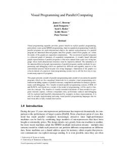
Extended Drag-and-Drop Technique Based on the Direct Manipulation When a programmer describes a visual program, the programmer often move a child goal into its parent goal. The child goal is inserted into its parent goal by using mouse dropping. The conventional drag-and-drop technique is suitable in twodimensional space because it is originally developed for twodimensional space. The problem is that the drag-and-drop technique in three-dimensional space is difficult for programmers. There are two problems as follows: 1. Lack of the information of depth: It is difficult for programmers to recognize whether a child goal is collided with its parent goal or not in three-dimensional space. In the programmer' s viewpoint (the left part of Figure 2), the cylinder object which is moved by mouse is collided with the cube object. However, the cylinder object is not collided with the cube in the other viewpoint (the right part of Figure 2). Programmers have difficulty to inspect the information of depth because the display of a computer is two-dimensional.
Three-Dimensional Icon The visual program of “3D-PP” is built by combining pictorial programming elements. We prepare three-dimensional miniature objects as the principal programming elements mentioned above (Figure 1). The three-dimensional miniature objects are placed as three-dimensional icons. When programmers click one of the three-dimensional icons, the pictorial programming element appears in the center of the window. The shape of the three-dimensional icon corresponds to its original pictorial programming element.
A programmer's viewpoint.
The other viewpoint.
Figure 2: Lack of the information of depth. Figure 1: Three-dimensional icons. Direct Manipulation The left side of :- in the textual GHC code is visualized as a parent pictorial programming element in “3D-PP” (parent goal). The right side of :- of the textual GHC code is visualized as a child pictorial programming element in “3D-PP” (child goal). The visual program of “3D-PP” is composed of hierarchical nesting boxes of pictorial programming elements. When the programmers manipulate a three-dimensional program element by using a mouse, the program element should be moved in accordance with the mouse movement. However, they have the difficulty to specify the position of the program element because the mouse is two-dimensional. To solve this problem, we apply direct manipulation technique [18] to operate a three-dimensional program element. The direct manipulation is a operation in which programmers' operation directly invokes the reaction of the system.
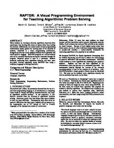
2. A far object is represented small: Three-dimensional program elements are projected on a two-dimensional window after the perspective transformation. The program element which is far from the viewpoint is represented smaller than the program element which is near the viewpoint through the perspective view. Programmers have the difficulty to drag-and-drop the goal which is near the viewpoint into an other goal which is near the viewpoint because sometimes the rear side goal is hidden by the front side goal (Figure 3). To solve the problems mentioned above, we propose extended three-dimensional drag-and-drop technique to suit a threedimensional space. We prepare a plane which restricts the movement of a program element (Figure 4). The normal of the restrictive plane is (dx , dy , dz ). The restrictive plane is always parallel to the display of a computer. When programmers move the program element while holding down the left button of the mouse, the program element is moved along the restrictive
structure of the visual program even though the method of representation is three-dimensional.
Figure 3: The rear side object is hidden by the front side object. plane. The programmers can move the program elements in the three-dimensional space as if the program elements are placed in a two-dimensional space. The programmers do not need to mind whether the goal which is being dragged is collided with the other goal to be dropped or not. The
restrictive plane y
x
display
ground z
viewpoint
(dx, dy, dz)
Figure 4: The restrictive plane that is parallel to the display.
When an object overlaps with other objects, showing the object semi-transparently is effective [16]. By using the semitransparent representation, the system can control the complexity of the information presented to programmers. It is not always necessary that all of the goals should be represented. Only a part of program should be shown to the programmers by using the nest level of each goal. The nest level of a goal on which a programmer focuses is Level 0, the nest level of the sub-goal of the focused goal is Level 1 and the nest level of the sub-sub-goal is Level 2. The system represents the goals whose nest levels are less than Level 2. The rest of the program is hidden by using the nest level filtering. Accessibility of the inside of a program structure It is important that programmers can easily explore the inside of the structure of a visual program because good accessibility of the structure of the program can improve the the programmers' capability of comprehension. The goals whose nest level are Level 0 are focused in default setting. When a goal whose nest level is Level 2 is double-clicked by a programmer, the goal is swelled and its sub-goals and sub-subgoals appear (Figure 6). The double-clicked goal is focused and its nest level becomes Level 0. When a goal whose nest level is Level 0 is double-clicked by a programmer, the goal is shrunk. Its sub-goals are hidden. The hierarchical program structure of “3D-PP” is accessible by using this technique. Combining the semi-transparent representation by using the nest level filtering and the double-click browsing are effective to solve both the “Small Screen Problem” and the “Scaling Up Problem.”
program element is represented semi-transparently while it is being dragged. Other program elements are not hidden by this semi-transparent representation (Figure 5).
Figure 6: The double-click browsing. Figure 5: Other program elements are not hidden.
Sample Program GHC sample code: begin
Semi-Transparent Representation The structure of the visual program of “3D-PP” is multilayered. A goal can contain more than two sub-goals. One of the sub-goals can also contain more than two sub-sub-goals. When the scale of a visual program becomes large, the total number of goals increase. If the total number of goals is too many, programmers cannot comprehend or inspect the
:-module main. main:-primes(1000,LP),io:outstream([print(LP),nl]). primes(Nth,LP):-gen_primes(AB,Ps), pkup(Ps,Nth,AB,LP). gen_primes(AB,Ps):-gen(AB,2,Ns)@lower_priority, sift(Ns,Ps). gen(abort,_,Ns):-Ns=[]. alternatively. gen(AB,N,Ns):-Ns=[N|Ns2],N2:=N+1,gen(AB,N2,Ns2).
sift([],Zs):-Zs=[]. sift([P|Xs],Zs):-Zs=[P|Zs2],filter(P,Xs,Ys), sift(Ys,Zs2). filter(_,[],Ys):-Ys=[]. filter(P,[X|Xs],Ys):-X mod P=\=0 | Ys=[X|Ys2],filter(P,Xs,Ys2). filter(P,[X|Xs],Ys):-X mod P=:=0 | filter(P,Xs,Ys). pkup([P|_], Nth,AB,LP):-Nth=:=1 | LP=P, AB=abort. pkup([_|Ps],Nth,AB,LP):-Nth=\=1 | Nth2:=Nth-1,pkup(Ps,Nth2,AB,LP).
Execution of Three-Dimensional Visual Program “3D-PP” can visualize both the editing and execution of a visual program.
GHC sample code: end
The sample code of GHC shown above is the program which can calculate and output the value of the 1000th prime number. Figure 7 is the visual program which corresponds to the sample code of GHC. primes is the goal which calculates and outputs the value of the 1000th prime number. gen primes generates a sequence of prime numbers. pkup picks up the value of the 1000th prime number and transfers to primes. io:outstream registers the output data from primes. Although gen primes and pkup contain gen, shift and pkup (recursive goal), only the goals whose nest levels are less than Level 2 are represented.
a
b
c
d
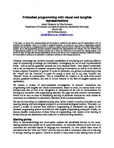
Figure 8: Execution of a visual program. Figure 8 is the snapshot of the execution of the sample program shown above. Programmers can execute the visual programs which are described in the same single window. The execution processes are represented from Figure 8-a to Figure 8-d with animated representation.
Figure 7: Snapshot of “3D-PP.”
Figure 8-a is the snapshot when gen and shift are generated after the reduction of gen primes. gen generates the sequence of natural numbers. shift removes the multiples of prime numbers from the sequence of natural numbers. shift transfers the results to its sub-goal. Figure 8-b is the snapshot when filter is generated after the reduction of shift and pkup. filter removes the multiples of two from the sequence of natural numbers. The value of the argument of pkup changes from 1000 to 999 because a prime number (two) is generated. Figure 8-c is the snap-
shot when the prime numbers are two, three, five and seven. The value of the argument of pkup changes from 999 to 996. When the value of the 1000th prime number is outputted, the value of the argument of pkup changes to one at the same time. Figure 8-d is the final phase of program execution. io:outstream registers the value of the 1000th prime number (its value is 7919) as the output data. Related work PrologSpace[22], VisuaLinda[6] and Cube[7] adopt threedimensional program representation. PrologSpace is based on a logic programming language Prolog. VisuaLinda is based on a concurrent programming language Linda. Cube is based on a concurrent logic programming language. PrologSpace is built on top of VisualProlog. VisualProlog is a version of Prolog that provides support for X windows, widget, three-dimensional graphics, animation and audio. PrologSpace is composed of at least four panes. In this paper, our visual programming system “3D-PP” is composed of a single window. VisuaLinda visualizes the state of the program execution of a concurrent programming language Linda. The multi-processes and the time flow of the program of Linda are visualized. The movement of the viewpoint in VisuaLinda requires the operation of three scroll bars. Each of the three scroll bars correspond to x, y and z coordinate axis of three-dimensional space. Manipulating a scroll bar is not intuitive for users when the users change the viewpoint. In this paper, programmers can change the viewpoint directly by using mouse movement in “3D-PP.” VisuaLinda does not visualize the editing of a program. “3D-PP” can visualize both the editing and execution of a visual program. Cube visualizes a node as a cube. Cube visualizes a passage of data as a pipe. The program of Cube is executed after the translation between a visual program and a textual program. The program of “3D-PP” is executed by “GHC engine” and “GUI part.” The execution speed of “3D-PP” is fast because “GHC engine” can directly execute a visual program without any external systems. “GHC engine” does not translate a visual program to a textual program.
ming Languages, IEEE Computer, Vol.28 No.3, pp.45– 54, March 1995. 2. P. T. Cox, F. R. Giles and T. Pietrzykowski: Prograph: A Step towards Liberating Programming from Textual Conditioning, 1989 IEEE Workshop on Visual Languages, Rome, pp.150–156, 1989. 3. George W. Furnas: Generalized Fisheye Views, In Proceedings of ACM CHI' 86 conference on Human Factors in Computing Systems, pp.16–23, Association for Computing Macinery, 1986. 4. D. A. Henderson and S. K. Card: Rooms: the Use of Multiple Virtual Workspaces to Reduce Space Contention in a Window-Based Graphical User Interface, ACM Transactions on Graphics, Vol.5, No.3, pp.211– 243, July, 1986. 5. Ken Kahn: ToonTalk — An Animated Programming Environment for Children, Journal of Visual Languages and Computing, pp.197–217, June, 1996. 6. Hideki Koike, Tetsuji Takada, Toshiyuki Masui: VisuaLinda: A Framework for Visualizing Parallel Linda Programs, In Proceeding of 1997 IEEE Symposium on Visual Languages (VL' 97), pp.174-180, 1997. 7. Marc A. Najork: Programming in Three Dimensions, Journal of Visual Languages and Computing (1996) 7, pp.219-242, 1996. 8. Hideki Mitsunobu, Takashi Oshiba and Jiro Tanaka: Claymore: Augmented Direct Manipulation of ThreeDimensional Objects, In Proceedings of Asia Pacific Computer Human Interaction 1998 (APCHI98), pp.210-216, IEEE Computer Society Press, Shonan, Japan, July 15th to 17th, 1998. 9. Koji Miyagi, Takashi Oshiba and Jiro Tanaka: ThreeDimensional Visual Programming System 3D-PP, 15th Conference Proceedings Japan Society for Software Science and Technology, pp.125-128, September, 1998 (in Japanese).
10. Takashi Oshiba and Jiro Tanaka: “3D-PP”: ThreeDimensional Visual Programming System, In Proceeding of 1999 IEEE Symposium on Visual Languages (VL' 99), pp.189-190, IEEE Computer Society Press, Summary Tokyo, Japan, September 13th to 16th, 1999. We propose a visual programming system with three-dimensional representation. We apply the direct manipulation to operate 11. Takashi Oshiba and Jiro Tanaka: Three-Dimensional a three-dimensional program element. We also apply the exModeling Environment “Claymore” Based on Augtended drag-and-drop technique for describing the program mented Direct Manipulation Technique, In Prostructure of nesting boxes. We propose the semi-transparent ceedings of The 8th International Conference on representation by using the nest level filtering and the doubleHuman-Computer Interaction (HCI International ' 99), click browsing to improve the both of the “Small Screen pp.1075-1079 (Volume 2), Munich, Germany, August Problem” and the “Scaling Up Problem.” We implement the 22th to 27th, 1999. three-dimensional visual programming system “3D-PP” by 12. Takashi Oshiba and Jiro Tanaka: “Claymore”: Threeusing these techniques. Dimensional Modeling Tool Based on Augmented REFERENCES Direct Manipulation Technique by Using Additional 1. Margaret Burnett et al: Scaling Up Visual ProgramInformation, Workshop on Interactive Systems and
Software VI (WISS' 98), pp.195, December, 1998 (in Japanese). 13. Takashi Oshiba and Jiro Tanaka: The ThreeDimensional Modeling Tool “Claymore”: Augmented Direct Manipulation Technique by Using Additional Information, 15th Conference Proceedings Japan Society for Software Science and Technology, pp.161-164, September, 1998 (in Japanese). 14. Takashi Oshiba: Direct Manipulation Technique for 3D Objects, Bachelor Thesis of Information Sciences, Third Cluster of Colleges, Univ. of Tsukuba, 1998 (in Japanese). 15. Takashi Oshiba, Hideki Mitsunobu and Jiro Tanaka: Direct Manipulation for 3-D Virtual Space, 14th Conference Proceedings Japan Society for Software Science and Technology, pp.73-76, September, 1997 (in Japanese). 16. Jun Rekimoto: The Information Cube: Using Transparency in 3D Information Visualization, Workshop on Interactive Systems and Software I (WISS' 93), pp.1-8, September, 1993 (in Japanese). 17. M. Sheelagh, T. Carpendale, David J. Cowperthwaite and F. David Fracchia: Extending Distortion Viewing from 2D to 3D, IEEE Computer Graphics and Applications, Vol.17, No.4, pp.42-51, 1997.
18. Ben Shneiderman: Direct Manipulation: A Step Beyond Programming Languages, IEEE Computer, Vol.16, No.8, pp.57-69, 1983. 19. Jiro Tanaka, Hideki Mitsunobu and Takashi Oshiba: Claymore: Three-Dimensional Modeling Tool, In Proceedings of The 20th International Conference on Software Engineering (ICSE98), pp.67-72 (Volume II), IEEE Computer Society Press, Kyoto, Japan, April 19th to 25th, 1998. 20. Masashi Toyoda, Buntarou Shizuki, Shin Takahashi, Satoshi Matsuoka and Etsuya Shibayama: Supporting Design Patterns in a Visual Parallel Data-flow Programming Environment, In Proceeding of 1997 IEEE Symposium on Visual Languages (VL' 97), 1997. 21. Kazunori Ueda: Guarded Horn Clauses, ICOT Technical Report, TR-103, 1985. 22. Masoud Yazdani and Lindsey Ford: Reducing the Cognitive Requirements of Visual Programming, In Proceeding of 1996 IEEE Symposium on Visual Languages (VL' 96), pp.225-262, 1996.