Accelerator-Driven Transmutation Technology for Energy Production and Nuclear Waste Treatment*. R. A. Jameson, G.P. Lawrence, S.O. Schriber. Los Alamos ...
230
Accelerator-Driven Transmutation Technology for Energy Production and Nuclear Waste Treatment* R. A. Jameson, G.P. Lawrence, S.O. Schriber Los Alamos National Laboratory Los Alamos, NM 87545, USA Abstract
New concepts recently developed at Los Alamos show that the use of intense particle accelerators affords unique opportunities for electrical power generation, from plentiful fuel such as thorium, with little long term waste legacy. The concept can aLsoeffectively transmute existing actinide and fission product wastes. The physical processes to be used are different and more advanced than earlier ideas: the new concept uses the accelerator beam to generate intense flux levels (1015 - 1016 n/cm2*sec) of thermal energy neutrons that efficiently transmute fuels or actinide wastes via a two-step capture/fission process, and also efficiently transmute fission products to stable or short-lived end-products. Effective cross sections for the actinide transmutation are enhanced at higher flux levels, and thermal-energy fission-product cross-sections are also higher than at fast neutron energies. The high neutron flux values and large cross-sections allow large transmutation rates with very small resident material inventories, a factor of 100 or more smaller than earlier methods. This feature, realized in a dilute, continuously flowing system, results in significant safety and engineering advantages. Proton cw accelerators in the 800-1600 MeV, 50-250 mA class are required, depending on the desired plant configuration. The technology base for such accelerators has been thoroughly reviewed and is feasible. Beam dynamics and optimization issues related to insuring low beam loss along the linac are outlined.
1 INTROl3UCTION
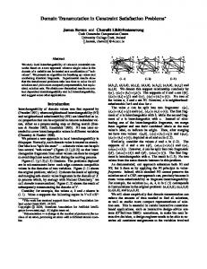
including enough excess neutrons to convert its own highlevel wastes to stable or short-lived products. Speed of Processing -Use of a sufficiently high flux of thermal neutrons, such as can be provided only by an accelerator-driven system, allows advantage to be taken of a high cross-section, two-step burning process for fissioning long-lived actinide wastes to stable or short-lived fission products, with excess neutrons left over. The high neutron cross section and high flux allows the amount of material required to achieve a given bumup rate to be two orders of magnitude or more smaller than in a reactor system with the same bumup rate. Further, fission product capture cross sections are higher for thermal neutrons, and there are excess neutrons available for burning them. 9 Safety -The neutron producing target/blanket assembly is thus a small radionuclide source term and is strongly subcritical, removing any possibility of a criticality accident. The accelerator driver can be instantly shut off, by a variety of means. Environmental - The low material inventory, coupled with optimized chemical processing, results in minimization of waste streams and small end-of-life residues, allowing onsite management of remaining low-level waste. The general features of the Los Alamos Accelerator Transmutation of Waste (ATW) concept are shown in Figure 1. The plant contigumtion has a wide range of options depending l
l
TO THE ATW CONCJFI-S
The need for clean energy supplies is a world problem. Nuclear power is presently under the onus of a legacy of existing long-lived radioactive waste that must be disposed of, and more waste must not be allowed to result from future systems. Indeed, until the waste problem is solved, public opposition to nuclear power will undoubtedly continue. The required solution must reduce both the volume of existing waste and its radioactivity, so the waste becomes benign by the end of a period over which a society might be able to retain control., say a few hundred years. StudieslM3 at Los Alamos indicate that an acceleratordriven thermal neutron source could address both the transmutation of wastes and clean generation of electrical power in a more complete, safe, and environmentally responsive way than earlier approaches. The thermal neutron source approach has the following advantages: Comple:teness - The system is unique in that it can process both long-lived actinides and fission product wastes, while producing net electrical power. In an energy production configuration,, fertile material (232Th or 238U) is converted to fissile fuel (233U or 239Pu) and burned to produce power, l
* Work supported by the US Department of Energy
> lO’~/cn+-s Thti Neuhon flux
STABLE 6 SHORT LIVED PROOWTS
Figure 1. General features of the ATW concept. on the emphasis among a number of applications, including transmutation of existing waste, generation of electric power, or production of special nuclear materials. Typical plants of 20~00-6000MWt capacity would require a linear accelerator with beam power of 200-400 MW, translating to proton accelerator energies in the range 800- 1600 MeV at continuous currents of HO-250 mA. The proton beam is delivered to a heavy metal (Pb, W or U) target, producing neutrons. A heavy water moderator (several meters in diameter) surrounds the spallation target to slow the neutrons down to thermal energies. Fluxes greater than 2-3~10’~ n/cm2.sec are
231 produced over a large active volume. The materials to be transmuted are carried in a dilute (by volume), low inventory system using continuous material feed in a carrier material such as aqueous media, oxide slurries, or molten salt. Because the inventory is small, chemical partitioning processes leading to the highest decontamination factors can be used. If a molten-salt carrier system can be successfully developed, the salt’s high thermal-to-electric conversion compatibility can be used to substantia.lly increase the efficiency of electricity production, and also would enable advanced fluoride chemistry or physical methods to be used for removal of fission products from the actinide fuel. Base-case ATW systems have been laid out using current, credible technology3, and options for substantial improvement through development have been identified. The base case is driven by a 250 rnA, 1600 MeV accelerator requiring 900 MWe. The proton beam is split to four target blanket modules, each producing -1.5 GWt from actinide fission for a total system power of 6 GWt. The system will burn the actinide waste horn -7.5 LWR’s, i.e. about 2450 kg/yr. Each blanket also provides excess neutrons to transmute the vc and 1291from 7.5 !LWRs (-250 kg/yr) to stable products. The thermal-to-electric conversion efficiency is 30%, yielding -1000 MW of net (after driving the accelerator) electrical power to the grid. A crucial aspect of these systems is called the “mass balance”; an exhaustive analysis of all material entering and leaving the system. This is a revealing method for comparison among transmutation approaches, and the recently conve.ned US National Acajdemy of Science review on radwaste has requested that all approaches furnish a comprehensive mass balance. The preliminary results for the baseline LWR waste burner outlined above are, for the yearly transmutation rates cited: per kilogram of waste burned per year, 30 g of radionuclides with halflives 2 30 years are produced in the spallation target; per kilogram of fission products burned per year, one kilogram of Class C or better transmuted by-product is discharged; per kilogram of actinide burned per year, < 250 liters of non-TRU liquid discharge (mainly water); N2 and C@ are produced; 156 g of inerts (phosphates, sodium, ash) are produced; anld 65 g of radionuclides with halflife > 30 years (135Cs, Io7Pd, g3Zr) are produced.
2 ACCELERATOR REQUIREMENTS In recent papers4-6, we have outlined the basic accelerator requirements, presented point designs, discussed the design approach for near-term and longer-range improved options, and the technology issues and technology base. Very briefly summarized, the required room-temperature technology is in hand. An integrated “front-end” funneled system up to at le.asl 40 MeV should be constructed as a testbed for final engineering development and reliability/availabilit~ development. Two major reviews, by ERAB7 and JASON , We believe that have emphasized these points. superconducting rf technology may be appropriate in the longer range for energy-production systems where efficiency is paramount, and we are initiating studies in this areas. A key design factor for these long, high-intensity linacs is to insure that beam losses along the linac are kept low enough to insure “hands-on” maintenance, without remote manipulators, over the lifetime of the facility. The reference design concepts used to date9 address low beam loss by:
Use of the radiofrequency quadrupole (RFQ) to bunch and preaccelerate the beam with very good emittance preservation, with operation well below the current limits of the device. Current limitations on a single injection channel are one reason for the funneled approach; a second is to fill every bucket of the doubled-frequency downstream linac for minimum emiltance at a given current 9 Attention to keeping the beam matched well across machine structure transitions (e.g. from RFQ to DTL to CCL, or where magnet or tank groups change), minimizing the number of such changes, and trying to make such changes at the lowest energy, where beam loss is less important. Attention to achieving high “rms aperture ratios”, the ratio of transverse aperture lo rms beam size (at flutter factor maximum), and longitudinal bucket width to rms beam length. The strong economic tradeoff between linac length and gradient argues for constant accelerating gradient along most of the linac (-1 MV/m at present rf costs); thus the longitudinal focusing weakens rapidly at higher energy, and some longitudinal emittance growth is typically allowed. In the transverse direction, strong focusing is provided, the aperture is kept large (al some penalty in rf losses), and rms aperture ratios of at least 10 are sought. The design is simulated in a fully nonlinear, 2r/, - 3-D particle-in-cell simulation code, using a large number of particles, and introducing various errors within engineering tolerances. If these runs show a well-matched beam, adequate aperture factors, and I~Q particles lost (beyond those not accepted by the RFQ), the design is judged satisfactory. The criteria are thus seen to be a combination of beam dynamics, numerical consideration, and cost and engineering factors. The beam dynamics in the codes has been thoroughly validated in terms of rms behavior in different experiments at different laboratories. The behavior of the total beam is another matter - few accelerator laboratories, beyond LAMPF, have had to worry about very small beam losses in linacs (typically, fractional losses must be kept below 10m5to lo8/m, more str’m gen1 at higher energy). The beam dynamics codes contain approximations that basically limit their validity. At LAMPF, detailed beam halo measurements were made to the 10e4 - IO5 level that qualitatively agreed with simulations. but it was observed that the halo patterns were different from day-to-day. The best validation of loss prediction is a comparison lo between the residual activity pattern along the LAMPF linac, accumulated over its 20-year operating history, compared to the beam spill prediction using an as-built datafile in the simulation code with a large number of particles. Losses patterns at spill areas where machine transitions occur (more abrupt than we would now allow) arc accurately predicted. The simulations predicted all measured quantities to lo-15%, except for total beam loss, which is sensitive to the tail population. “Design” and “production” input distributions to the simulation overestimated the total loss by x3 and x10 respectively. With careful use, it is believed (RAJ) that the codes allow qualitative assessment, and rough quantitative assessment,to fractional losses of -10. 3 - 104. The numerical aspects have also received detailed attention at Los Alamos. With supercomputers, brute force simulation of very large numbers of particles could be done (the required number of particles per bunch in the ATW machines is l
l
l
232 -2x 10⁹). Careful attention1 lv12 has been given to appropriate fitting of measured particle distributions; modified Weibull distributions give good fits, whereas combinations of Gaussians are very poor. The statistics of the outliers can be independently assessed, with predictive power that is undoubtedly better than the code physics deserves. An engineering safety factor based on the rms aperture factors is then used, a practice based on experience such as LAhIPF’s and many circular accelcralors and storage rings around the world. The transverse rms aperture factor near the end of the LAMPF CCL is about 6.3; our preliminary ATW designs strive for at least 10. These criteria are rigorous, defensible in detail, and adequate lo proceed confidently with construction plans for linacs in this class. For all that, every accelerator builder knows that there is always room for a better job. For these high-intensity, low-beam-loss linacs where very high efficiency is also crucial, it is necessary to know that the designs are optimum with respect to a complex combination of beam-loss, efficiency, cost and other criteria and constraints. Optimization, for example, to the best rf frequency, aperture size, focusing strategy, injection conditions, and so on. And it is the case, presently, that while we can demonstrate adequacy, we cannot clearly describe the optimum for the high-intensity linac where low-beam-loss and high-efficiency are the primary objectives. The following paragraphs outline initial attempts by one of us (RAJ) lo define and address aperture factor optimization, within the constraints of other objectives.
3 LOW I3EAM LOSS DESIGN OPTIMIZATION The (transverse or longitudinal) (rms or total) aperture factors are the ratio of the accelerator bore or longitudinal acceptance to the corresponding (rms or total) beam size. Unfortunately, we do not have analytic relationships in general: there are (at least) two difficulties: Even the simplest rms formulas we have (see below) are nonlinear and coupled. Total beam size is of course the important quantity. “Halos” or “tails” can form around the beam from a variety of effects, but their extent cannot be predicted theoretically, nor even be related to the rms beam properties. Therefore optimization efforts must always keep the total beam size under survdllance using the full simulation codes. l
l
3.1 Design Philosophy -> Matched System
A beam focusing system has beam kinetic and internal field energy and potential energy from the external fields. The definition of a matched system is that the beam and its surroundings are in perfect equilibrium, including any nonlinear or time-varying effects. Our design philosophy is to try to achieve matching; our optimization philosophy should start with the matched condition, but is subject to practical constraints, An imbalance (mismatch) anywhere constitutes a source of free energy. There are many possible sources - independent or dependent on beam intensity, linear or nonlinear, static or time-varying. Via interaction with a nonlinearity, a mechanism, or dynamical path, exists for the free energy to convert to (coarse-grained) emittance growth, leading toward a new equilibrium (in the absence of further driving terms). The evolution can occur through single-particle or collective
motion, and be a stable or unstable process., with a rate that varies accordingly. For example, if there is a strong enough anisotropy of divergence between the degrees of freedom, an equipartitioning energy transfer between planes will occur through incoherent instabilities13-15, Irma-plane effects will result from mismatch even without instability, through the couplings between planes. Matching of the beam’s rms envelope equations of motion forms a robust basis for the design philosophy, describing an equilibrium condition for a uniform beam density distribution in a periodic focusing system: a20’y E(, = rd.
)
b*a’ y3 Eln = d.
(1)
where E denotes emitmncc (here total emittance), sub-orsuper-r-or-l the transverse or longitudinal plane, sub-n the normalization lo canonically preserved emiltance during transport or adiabatic acceleration, a and b the transverse and longitudinal radii, of an ellipsoidal beam bunch with uniform particle distribution, n is an integer describing the number of J3h’s in the transverse focusing period, and (5 is the phase advance over the distance n/X The phase advances at and 01 are each comprised of a beam-independent (zero-current) part, sot and 0~1, representing the external focusing fields of the linac, and a beamdependent part that is the counteracting space-charge effect: u 12= a;“-
IA3kn2(1-ff) a2by3
2/;1%l*ff u 12= flL2-
\A
a2by3
where we arc working with a smooth, small-angle, approximation to the focusing forces, k = (3&q)/@ m,c2), and ff = ellipsoid form factor - a/(3@) for ybla between approximately 0.8 and 5. The relationships among the beam emittances, sizes and phase advances (or “tunes”) arc the most fundamental way to look at the beam physics situation along the machine. The balance between external focusing forces and the space-charge self-defocusing of the nonrelativistic beam is seen in fit and 01, equaling zero at exact cancellation, with laminar (parallel) particle trajectories and zero divergence. The ratios ot/crot and o I/cro1 are called the tune depressions. Beam current, energy, and the operating frequency, usually used as primary quantities, are seen to be subsumed into these more basic relationships. The equations locally agree very well with simulation results along a typical linac. They are relatively insensitive to injected non-matched density distributions; the mechanism and asymptotic behavior of the (rapid and usually small) emittance growth from this effect are known14-15, and can usually be neglected for design and optimization. The consequences of ellipse and off-axis beam mismatch in these equations are also known16. Changes known apriori can be introduced into these equations, but they basically describe a linearized system in which there can be no emittance growth. A third important rms equation is known17, describing the condition known as “equipartitioned”, when there is energy balance of the potential and kinetic energies between the transverse and longitudinal degrees of freedom:
233 to know the acceptance behavior. A particle bunch is propagated through the linac, generating the appropriate space-charge forces, which are then applied to zero-current “test particles”. The test particles are injected at some cell on Rewriting this as eln/‘yb = b’ = em/a = a’ shows that the a grid overlapping the acceptance; relating test particles that divergences are equal when the beam is equipartitioned. The have survived downstream to their initial coordinates on the injected grid defines an acceptance boundary. In our initial products co, and at2, b2, are energies. Under reasonable design conditions (non-linearities and studies, we assume that the downstream channel is defined by rate-of-change of parameters not too large, certain resonances a linac with a constant characteristic - for example constant avoided), it is known that if Eqns (1) and (3) are locally trot and constant accelerating gradient. Depending on whether satisfied, cmittance growth is strongly avoided. These are the there is emittance growth, this may mean that the tune characonly general equations we have at present for the matched teristic of the downstream channel is not constant. Thus is is condition, so their simultaneous solution is now being not yet clear how the effective acceptance should be defined. explored as a design philosophy and basis for optimization. We have been discussing matching using equations for rms There is a practical caveat, however. Matching using Eqn conditions in periodic systems - a useful construct for rms (1) alone is relatively easy and produces “smooth” beams. injection matching or for local conditions along the linac. Achieving equipartitioning has hardly been explored yet, but Introduction of acceleration and smoothly but fairly rapidly in some cases, it appears costly. For example, it may be hard changing parameters is needed. In I. Hofmann’s words14, “An to achieve the proper ratio of emittances. Because coherent rms matched beam is (intrinsically) mismatched if the instability mode thresholds are involved in this mechanism, nonlinear field energy term [or externally supplied free energy there is also leeway around balance (a rule of thumb for elri/etn term - my addition] changes rapidly within a coherent )) 1 is to keep al/of 5 1.5). So the requirement for equipar- oscillation period...“. Simulations indicate this is a factor in titioning could be relaxed or abandoned, and some emittance typical rf linacs. Acceleration has been incorporated in the growth might be allowed from this or other mechanisms. It is envelope equations for 2-D beams19; a high priority is to extend this to 3-D bunched beams, as well as parameter not at all clear whether a linac with no emittance growth will have a better aperture factor than a different linac, set up with variations. Again, from a practical viewpoint, non-adiabatic parameter changes (even though smooth) are unavoidable - it a different prescription that allows some emittance growth But it seems that a tborough understanding of a design is of interest to determine if effective compensation (to approach that intrinsically avoids emittance growth is a very prevent emittance growth) is possible. good starting point, from which the consequences of 3.2 Perspective on ATW CCL compromise might be assessed. With three equations, three variables can be left free while What does an ATW CCL linac look like from the the others are fixed. The coupled, nonlinear equations are perspective of tunes, tune shifts, equipartitioning, and other generally impossible to solve for analytic scaling relationships matching aspects? Assume a coupled-cavity linac from 20(for example, solutions for a and b). Guided by numerical 1600 McV, with a constant trot = 800, constant real-estate examples, some progress has been made that will be reported accelerating gradient of 1 MV/m, frequency = 700 MHz, & = elsewhere. One of the most sought results is how to optimize -300, aperture = 2.5 cm radius, current = 140 mA. An rmsthe choice of frequency to maximize the aperture factors. It matched beam is injected with transverse, normalized, rms has become quite clear is that this is by no means obvious! In the transverse plane, the linac aperture may remain emittance of 0.02 cm.mrad (about the smallest that might be constant with energy, or vary as some function, say of PA, and achieved at this current from the ion source/REQ/DTL), and this will strongly affect the optimization. The transverse and longitudinal normalized rms emittance of 0.04 cm.mrad. longitudinal aperture factors usually will not optimize at the Solution of Eqns (1) shows: 4 ~9/q,~ rises as (0.4,0.62,0.91) at (20,200,16GQ] MeV. same place, so a criterion to balance them must be chosen. 9 ~l/cr,~ falls as (0.5,0.24,0.08 at (20200.1600) MeV. In some cases (choices of free vs. fixed variables), it has been found numerically that the aperture factor will maximize . the transverse rms aperture factor rises as { 13,17,32). at the same tune depression in that plane, over a wide the longitudinal rms aperture factor assuming that the variation of any oif the variables used to arrive at that tune bucket width remains 3$, rises from 3.5 to 9; assuming the depression. Such a result is surprising and important to bucket shrinks as (1 - (~~/cr~l)~), falls from 1.2 to below 1. understand, so a strong effort is being made to find an analytic Simulation shows the beam to be very smooth in the rmssolution that will elucidate the effect. matched sense of Eqn (l), without betatron or synchrotron In the longitudinal plane, there is a further complication. oscillations. There is transverse rms emittance growth of Within the framework of the smooth approximation and no x1.3, but emittance growth of the total beam peaks at x5 acceleration, it has been shownI that the longitudinal around 300 MeV, and levels off to -x4. The transverse rms acceptance width would shrink as (1 - (01/oo1)2). With beam radius shrinks continually under this strong focusing and acceleration, numlerical simulation shows that the bucket the transverse rms aperture factor looks good (-37); however, width does not shrink this fast. There is at present no theory the aperture factor based on total beam radius is -5.7. that gives the effective acceptance under accelerating and The longitudinal rms emittance grows steadily to 1600 space-charge conditions, It might be that a useful relationship MeV, reaching x2.1, with total emittance growth of x7-8. could be derived using some of the recent understanding of Factoring these rms growths into local solutions of Eqn.(l) how free energy affects the beam dynamics. For the ATW produces excellent agreement. designs, we are exploring the acceptance shrinkage numerically, because it is crucial to the aperture factor design
El”_ 0’ us ---1=Em (T a
l
234 Inspection of the the coherent instability thrcsholds13 shows that the operating tune depressions for the first few MeV are below the thresholds; emittance transfer from longitudinal to transverse is indeed seen in the simulation, stopping as soon as the tunes rise above threshold. Above 200 MeV, the ratio b’/a’ is level at -0.8, indicating no further transfer. al/o-t is cl and decreasing (Hofmann indicates that modes in [his regime are negligible) but ut/aot is 70.8 anyway, well above the thresholds. Additional runs were made with the transverse rms input emittance doubled to 0.04 cm.mrad, and doubled again. The tune progressions are similar. Transverse total emittance growth was -x3 and -x1.5 at 0.04 and 0.08 input, respectively. The total beam radius at 1600 MeV for the 0.02 input is only -20% smaller that that for the 0.08 input. Longitudinal growths remained nearly the same. The initial instability is avoided at higher input emittance. Above 200 MeV, the b’/a’ ratio is lower with higher input emittance, but no transfer occurs for the same re.asons. Thus there appears to be no emittance growth from rms mismatch or coherent instability effects; yet there is clearly a large and continuous source of free energy, converting primarily to longitudinal rms emittance growth and halo formation in both planes. It is believed this is due to rapidly changing parameters and acceleration, and so we plan to determine ‘the amount of free energy available from these effects and how it gets converted into emitlance growth. In this linac with constant real-estate accelerating gradient, 0,’ decreasesas $( 1 - (l/$)) l/2, the space charge terms decrease as 9, and the strong focusing, constant oat recipe results in the rapidly changing transverse tune during the first few hundred McV . Summarizing, the intended goal of these studies is to describe an optimum design for ATW-class linear accelerators, and to understand the consequences of the inevitable compromises entailed. ACKNOWLEDGEMENTS Thanks are extended to G.P. Boicourt for making the simulation runs. The ATW concepts and the concepts and procedures for matched beams are the result of work by a large number of our colleagues at Los Alamos and elsewhere, who are gratefully acknowledged. REFERENCES [I]
C.D. Bowman, et. al., “Nuclear Energy Generation and Waste Transmutation Using an Accelerator-Driven Intense Thermal Neutron Source”, LA-UR-91-2601, Los Alamos National Laboratory. [2] R.A. Jameson, Compiler, “Specialist Meeting on AcceleratorDriven Transmutation Technology for Radwaste and Other Applications”, 24-28 June 1991, SaltsjSbaden. Stockholm, Sweden, spans. by Los Alamos National Laboratory and Swedish National Board for Spent Nuclear Fuel (SKN), LA-12005-C, SKN Rpt. No. 54 [3] E.D. Arthur, H.J. Dewey, “The Los Alarnos Accelerator Transmutation of Nuclear Waste (ATW) Concept”, presented to the Symposium on Separations Technology and Transmutation Systems,, NAS/NRC Review, Washington, DC, Jan. 13, 1992, LA-UR-!>2-65, Los Alamos National Laboratory, 1992. [4] C.P. Lawrence. High-Power Proton Linac for Transmuting the Long-Lived Fission Products in Nuclear Waste”, LA-UR-91-
1335. IEEE Particle Accelerator Conference, May 1991, San Francisco, CA. [5] G.P. Lawrence, R.A. Jameson. S.O. Schriber, “Acceleraror Technology for Los Alamos Nuclear-Waste-Transmutation and Energy Production Concepts”, LA-UR-91-2797, Proc. ICNES ‘91. to bc published in Fusion Technology. [6] R.A. Jameson, G.P. Lawrence & C.D. Bowman, “AccelerarorDriven Transmutation Technology for Incinerating Radwaste and for Advanced Application to Power Production”, 2nd european conference on accelerators in applied research and technology (ecaart), 3-7 September 1991, Frankfurt-am-Main, Germany, LAUR-91-2687. [7] “Accelerator Production of Tritium (APT), February 1990, A Report of the Energy Research Advisory Board to the USDOE. DOE/S-0074. [8] S. Drcll, Chrmn, “Accelerator Production of Tritium (APT)“, JASON, The MITRE Corp., JSR-92-310, January 1992. [9] T.P. Wangler, et. al., “Linear Accelerator for Production of Tritium: Physics Design Challenges”. Proc. 1990 Linear Accelerator Conference, lo-14 Sept. 1990, LA-12004-C. p. 548, Los Alamos National LAboratory, 1990. [lo] R.W. Gamett. R.S. Mills, T.P. Wangler, “Beam Dynamics Simulation of the LAMPF Linear Accelerator”, Proc. 1990 Linear Accelerator Conference, lo-14 Sept. 1990. LA-12004-C. p. 347, Los Alamos National Laboratory, 1990. (111 G.P. Boicourt and R. A. Jameson, “A Statistical Approach to the Estimation of Beam Spill”, Proc. 10th Linear Accelerator Conf., Montauk, New York September 10-14. 1979, Brookhaven National Laboratory report BNL 51134, p. 238, September 1980. (121 G.P. Boicourt, “A Probability Function To Fit Radial Distributions in PARMILA Simulation Beams”, 1983 Particle Accelerator Conf., IEEE Trans. Nucl. Sci, Vol. NS-30, No. 4, August 1983, p. 2534. [13] I. Hofmann.. “Emittance Growth of Beams Close to the Space Charge Limit”. 1981 PAC. IEEE Trans. Nucl. Sci., Vol. NS-28. No. 3, June 1981. p 2399, and, I. Hofmann, 1. Bozsik.“Computer Simulation of Longitudinal-Transverse Space Charge Effects in Bunched Beams”, 1981 Linac Conf.. October 1981. LA-9234-C. Los Alamos National Laboratory. Feb. 1982, p. 116. [14] T.P. Wangler, F.W. Guy, ‘The Influence of Equipartitioning on the Emittance of Intense Charged-Particle Beams”, 1986 Linear Accelerator Conference, Stanford Linear Accelerator Center. SLAC-303 CONF-860629. pp. 336-345. [15] I. Hofmann. “Generalized Equations for Emittance and Field Energy of High-Current Beams in Periodic Focusing”, LA11132-MS, Los Alarnos National Laboratory, December 1987. [16] M. Reiser. “Emittance Growth in Mismatched Particle Beams”, 1991 Particle Accelerator Conf, IEEE Conf Record 91CH3038-7.
p. 2497. [17] R.A. Jameson, “Equipartitioning in Linear Accelerators”. 1981 Linear Accelerator Conf.. LA-9234-C. Los Alamos National Laboralory,p. 125 [18] R.L. Cluckstem. “Space Charge Effects”, in “Linear Accelerators”, Ed. Lapostolle & Septier, North-Holland Pub.. 1970, pp. 828-830. [19] E.P. Lee, R.K. Cooper, “Genera1 Envelope Equation for Cylindrically Symmetric Charged-Particle Beams”, Particle Accelerators, 1976, Vol. 7, 83-95.