Adaptive Scaling Factors Algorithm for the Fuzzy Logic Controller José Victor
António Dourado
Escola Superior de Tecnologia e Gestão Instituto Politécnico de Leiria Morro do Lena, Alto Vieiro 2400 Leiria, Portugal
[email protected]
Centro de Informática e Sistemas da Universidade Coimbra Departamento de Engenharia Informática Pólo II, Pinhal de Marrocos 3030 Coimbra, Portugal
[email protected]
Abstract
The fuzzy logic controllers contain a set of parameters that can be altered on line in order to modify the controller performance [ 1]. These include the scaling factors for each controller variable, the membership functions of the linguistic terms and the rules. The method presented in this paper uses the scaling factors to fine tune the fuzzy logic controller. The paper is organised as follows. In section 2 the fuzzy logic controller parameters of our basic controller are briefly described. Section 3 describes the adaptive scaling factor method. Section 4 presents an application example and section 5 the conclusions.
An on line method for adapting the scaling factors of the fuzzy logic controller is presented. Since most of the times tuning these controllers is not an easy task and very time consuming, the solution is to design an adaptive fuzzy controller. The objective of the proposed algorithm is to adapt the scaling factors according to a performance measure in order to fine tune the controller and improve the performance of the control system. An application example is presented for the temperature control of a heated air stream, process trainer PT326.
2. Fuzzy logic controller 1. Introduction The design of fuzzy logic controllers involves the appropriate definition of a parameter set. This includes the inputs and outputs of the fuzzy logic controller, the number of linguistic terms and the respective membership functions for each linguistic variable, the inference mechanism, the rules and the fuzzification and defuzzification methods. Even for someone who is not much familiar with this technology the design phase of these controllers is not too hard to learn. The main problem arises when it is necessary to tune the controller and some choices inherent to the controller parameter structure must be made. This task some times is very hard and can take several days, even weeks, in order to achieve a good performance. It depends much on the process that is being controlled [ 9]. Another important issue is the fact that most process dynamics changes with time or are nonlinear in nature. In spite of the robustness of the fuzzy logic controllers sometimes this is not sufficient to deal with it. The controller needs to be retuned to achieve good performance.
In the structure definition of a fuzzy logic controller it is necessary to define the inputs and outputs. The fuzzy logic controller implemented has two inputs and one output. The inputs are the error (1) and change of error (2). ek = rk − yk ∆ek = e k − ek − 1
(1) (2)
The output is the change of control (3). ∆u k = u k − u k − 1
(3)
The universes of discourse of the controller variables are E, ∆E and ∆U respectively. Their values range is [ -10,+10]. The number of linguistic terms for each linguistic variable is 5, LE = L∆E = L∆U = { NB, NS , ZO, PS , PB}
(4)
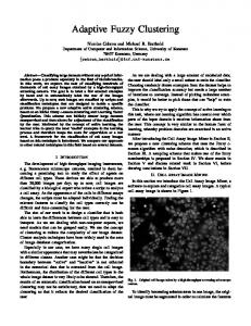
Triangular membership functions were used to represent the meaning of the linguistic terms (NB ≡
Negative Big, NS ≡ Negative Small, ZO ≡ Zero, PS ≡ Positive Small and PB ≡ Positive Big), shown in Figure 1.
Figure 1. Membership functions of the linguistic variable error.
Associated to each linguistic variable is a scaling factor. K e ≡ scaling factor for the error K ∆e ≡ scaling factor for the change of error K ∆u ≡ scaling factor for the change of control Scaling factors enable the use of normalised universes of discourse and play a role similar to that of the gain coefficients in a conventional controller [2]. The control policy is established in the rule base and expresses the knowledge of the designer about the process.
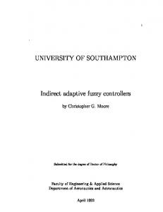
where cij is a crisp value instead of a fuzzy set. cij represent the point of minimum fuzziness in the consequent parts of the rules, i.e., the membership function centres. Figure 2 presents the rule base used in our controller. The rule base is complete, but it does not have necessarily to be since certain regions of the input domain are sometimes not of interest. In practical applications of fuzzy control almost no rule base is complete. To put all this working together is necessary an inference mechanism that gives the output signal to send to the process. The authors use the Mamdani (min-max) inference mechanism [ 3], even though the product-sum may enable better results. The option by the first derives from the fact that it is more appropriate to test the proposed method. Suppose that in a certain instant k , the values for the error and change of error are e k and ∆ek respectively. Using the Mamdani inference, the firing strength of a fuzzy control rule will be
(
f ij = min µLE (ek ), µL∆E ( ∆ek )
where
i
µ LE and i
j
)
µ L∆E represent j
(6) the
membership
functions of the linguistic values LE i and L∆E j . The output of the inference mechanism is a fuzzy value, so it is necessary to convert this fuzzy value into a real value, since the physical process cannot deal with a fuzzy value. This operation is called defuzzification; the inverse operation is fuzzification and the method used was the singleton fuzzifier. There are several defuzzification methods to convert a fuzzy value to a real value [ 10]. The height defuzzification method was used since it is simpler and, most of all, computationally very efficient. uij =
∑ ∑
i,j
f ij cij
i, j
(7)
f ij
The main idea of this method is that the larger the firing strength of a rule f ij , the more this rule
( )
contributes to the global fuzzy output. Figure 2. Rule base.
The rules are of the form: If e k is LE i and ∆ek is L∆E j then ∆u k is cij (5)
3. Adaptive scaling factors method The structure described in the previous section is the basic structure of the fuzzy logic controller. Depending on the choices made in the design phase we can have different types of fuzzy logic controllers: P, PD, PI or PID
fuzzy logic controller. In [ 6]it is shown that a fuzzy logic controller with the same characteristics of the traditional PID controller can be designed, by using only the error ( ek ) and the change of error ( ∆ek ) as its inputs. One way
covers the whole universe of discourse. From t 1 on, the error will be in the interval [− δ1 , δ1 ],where δ1 is the absolute peak value at time t 1 .
to achieve this goal is to serially connect an integrator to the output of the fuzzy logic controller, as shown in Figure 3. This controller is a PI fuzzy logic controller. ek rk +
Ke FLC
-
∆ek
∑
K∆u
Process
K∆e
Figure 3. PI fuzzy logic controller.
To design a PID fuzzy logic controller the PI fuzzy logic controller and the PD fuzzy logic controller must be connected in parallel, as in Figure 4. ek rk +
K∆u∑
Ke
Process
FLC
-
∆ek
K∆e
Kd
Figure 5: Response of a control system.
The reasoning is analogous when another peak value occurs at t 2 . The integral control component can be decreased at each peak value time according to the absolute value of each peak. Figure 6 presents the structure of the parameter adaptive controller purposed in [ 6]. Parameter Regulator
Peak Observer
Figure 4. PID fuzzy logic controller.
The role of the scaling factors in the fuzzy logic controller is very similar to that of the conventional PID parameters [ 2]. The rules for tuning the fuzzy logic controller by adjusting the scaling factors are generally derived by analogy from the rules for tuning of PID controllers. In PID control the integration component has an important role in the performance of the control system. The system response will be slow if the integration component is too weak and the system will became unstable if the integration component is too strong. So the ideal objective is to keep the integration component in such a way that our control system response is fast enough without overshoot. To achieve this the integration component does have necessarily to change with time. At an early stage of response the integration component takes a larger value and it is gradually reduced with time in order to increase the damping of the system and make the system more stable. Figure 5 presents the control system response, which can be divided into different phases by the peak value times. From the start time to the time when occurs the first peak value t 1 , the error of the system
ek
K∆u ∑
Ke
rk +
Process
FLC
-
K∆e
∆ek
Kd
Figure 6. Parameter adaptive PID fuzzy logic controller.
The parameter adaptive fuzzy controller is constituted by a PID fuzzy logic controller, a peak observer and a parameter regulator. The peak observer determines the peaks at the control system output and measures the absolute value of the peak. The parameter regulator tunes the controller parameters, scaling factors K ∆e and K ∆u , for each peak according to the peak value at that time. The algorithm for tuning the scaling factors K ∆e and K ∆u of the PID fuzzy logic controller is: K ∆e =
K ∆e
0
δk
(8)
K∆u = δk K∆u
(9)
0
such as furnaces, air conditioning, etc. and in the literature can be found several references [ 4, 5].
where K ∆e is the initial value of K ∆e and K ∆u is the 0
0
initial value of K ∆u ; δk is the absolute overshoot at time t k ( k = 1,2,K) .
This algorithm reveals some virtues but also some limitations. The algorithm substantially improves the performance of the control system if the value for the scaling factor K e is appropriate. A careful analysis of the algorithm shows that when the peak value becomes very small the value for the scaling factor K ∆e becomes very large and the control system can reach instability. In the present paper the authors propose an algorithm to improve the overall performance of the control system. While in the algorithm presented in [ 6]the scaling factor K e remains unchanged, when the first peak value occurs, the value of K e is changed in this work according with: If δl > ε rk then Ke = Ke − εδl
(10)
where δl is the overshoot, rk is the reference and
ε( ε > 0) is the final percentage allowed for the steady
state error. The tuning of the scaling factors K ∆e and K ∆u is as follows: if δk > 1 then
K ∆e =
K ∆e δk
K ∆u = δk
K ∆u A∆U
(11) (12)
else K ∆e =
δk A∆E
K∆u = δk K∆u
(13)
(14)
where A∆U and A∆E are the universes of discourse amplitude of the linguistic variable change of control and change of error respectively.
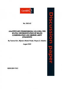
4. Application example This section presents the results of the algorithms described before when applied to the temperature control of a heated air stream (process trainer PT326), Figure 7. This type of process is found in many industrial systems
Figure 7. Pilot process PT326.
The process is very versatile with variable thermal time constants and variable time transport lag. It consists of a heating element controlled by a thyristor circuit that feeds heat into the air stream circulated by a centrifugal fan along a polypropylene tube. A thermistor sensor, which may be placed at one of three points along the tube length, senses the temperature at that point. The volume of air flow is manually controlled by a shutter on the fan inlet. A change in setting represents a supply side disturbance and the effects are easily demonstrated. The fuzzy logic controller receives from an A/D converter the sampled signal of the air-stream temperature sensor. The control signal is applied with a D/A converter to the thyristor power amplifier. The signals range is [ -10,+10V]. The algorithms described in the previous sections were implemented in Wuzzy [ 7, 8], a real-time fuzzy control tool for Windows 95 environment developed by the authors. It is suited to assist in the project, development and tuning of controllers, particularly fuzzy ones. Figure 8 presents the results of applying the fuzzy logic controller, described in section 2. The control system response presents almost no steady state error. The performance of the controller is quite good because the controller parameters were carefully tuned. For instance if the reference changes substantially, in spite of the robustness of the controller, the controller performance degrades a little bit. In Figure 8 other information besides the reference, output and the control signals is presented. On the top right are presented the fired rules in each iteration and down on the right the state space defined by the error and change of error.
Figure 10. Fuzzy logic controller with adaptive mechanism.
Figure 8. Fuzzy logic controller
Now consider the same controller but not well tuned. Figure 9 presents the results. The control system response is very poor, oscillating, showing that the adaptive version of the fuzzy logic controller can achieve good performance with that initial set of values. The values for the scaling factors were the following: K e = 0.2 ; K ∆e = 0.5 ; K ∆u = 01 . ;
(15)
Figures 10 and Figure 11 shows the results of the application of the fuzzy logic controller with the adaptive mechanism. On Figure 10 presents the first 250 iterations of the control system response and Figure 11 the following 250 iterations.
Figure 9. Fuzzy logic controller without adaptive mechanism.
With the adaptive mechanism the system oscillates at first but immediately the oscillations suffer strong resistance. After the 250 initial iterations the overshoot is small and after 500 iterations the error is practically null.
Figure 11. Fuzzy logic controller with adaptive mechanism.
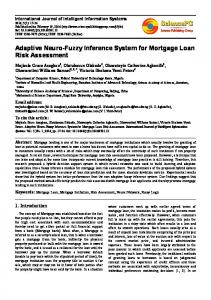
Figure 12. Scaling factors evolution.
Figure 12 shows the evolution of the scaling factors. The values assumed by K e are progressively reduced. K ∆e increases when a peak occurs to compensate the overshoot. K ∆u assume large values at the beginning since the initial value is big.
5. Conclusions The authors described the structure of the fuzzy logic controller and using information from the control system response propose an adaptive algorithm to fine tune the fuzzy logic controller. A performance measure, the peak value, was used to adapt on line the scaling factors. The algorithm was tested in the temperature control of a heated air stream and the control system performance was good.
Acknowledgements This work has been supported by JNICT - Junta Nacional de Investigação Científica e Tecnológica under PROGRAMA PRAXIS XXI/BM/1072/94 and CIÊNCIA.
References [ 1] D. Driankov, H. Hellendoorn and M. Reinfrank. An Introduction to Fuzzy Control. Springer-Verlag, 1993. [ 2] D. Filev and R. Yager. On the Analysis of Fuzzy Logic Controllers. Fuzzy Sets and Systems, 68:39-66, 1994.
[ 3] C. Lee. Fuzzy Logic in Control Systems: Fuzzy Logic Controller— Part I, II. IEEE Transactions on Systems Man and Cybernetics, 20(2):404-435, 1990. [ 4] L. Ljung. System Identification: Theory for the User. Prentice-Hall Inc., 1991. [ 5] A. Ollero and A. García-Cerezo. Direct Digital Control, Auto-Tuning and Supervision using Fuzzy Logic. Fuzzy Sets and Systems, 30:135-153, 1989. [ 6] W. Qiao and M. Mizumoto. PID Type Fuzzy Controller and Parameters Adaptive Method. Fuzzy Sets and Systems, 78:23-35, 1996. [ 7] J. Victor and A. Dourado. Wuzzy: A Real-Time Fuzzy Control Tool and its Application. Proceedings of AARTC’97, 1997. [ 8] J. Victor. Controlo Adaptativo Difuso. MSc Thesis. To appear, 1997. [ 9] C. Von Altrock. Fuzzy logic & Neurofuzzy Applications Explained. Prentice Hall PTR., 1995. [ 10] R. Yager. Knowledge-Based Defuzzification. Fuzzy Sets and Systems, 80:177-185, 1996.
Note: Wuzzy is a free software tool. It can be download from ftp://control.dei.uc.pt/pub/wuzzy.