purpose processors, with or without ISA extensions for 3D, or by specialized graphics ... extension to Intel x86 [5], AltiVec extension to PowerPC [6],. 3DNow! in AMD x86 [7], and MIPS-3D extension to MIPS64. [8]. However, these ..... [11] NVIDIA Corporation, High-Precision Graphics: Studio-Quality Color on the PC, 2002.
Adding 3D Graphics Support to PLX Xiao Yang and Ruby Lee Department of Electrical Engineering Princeton University {xiaoyang, rblee}@princeton.edu Abstract—PLX is a compact, fully subword-parallel instruction set architecture (ISA) for very fast multimedia processing. This paper adds floating-point instructions to PLX for 3D graphics processing, which is essential for applications such as games and digital content creation. Based on an analysis of the 3D graphics pipeline from an ISA point of view, we show the operations and data types needed. We present the FP ISA and demonstrate its use and performance with code examples from the 3D graphics pipeline. Keywords—processor architecture, instruction-set architecture (ISA), floating-point, multimedia, 3D graphics
I. INTRODUCTION Multimedia information processing is an important part of the workload for today’s computing platforms, ranging from high-end desktop workstations to low-end portable devices. High-performance multimedia processing is one of the key design goals for contemporary microprocessors. Common operations for media processing are part of the core ISA of processors instead of being merely ISA extensions, as in the past. PLX [1], developed at Princeton University, is a fully subword-parallel ISA designed specifically for very fast multimedia processing. The initial release of PLX includes only integer instructions targeting integer-based media applications, such as image and video processing. In this paper, we present the floating-point (FP) part of PLX designed for fast 3D graphics processing. 3D graphics is dominant in areas such as gaming, digital content creation, and simulation. Most 3D graphics applications are built on top of standard 3D graphics libraries, such as OpenGL [2] and Direct3D [3]. These libraries provide a set of APIs for the applications to specify the composition of the scenes and how they are to be rendered. Underlying these libraries is a 3D graphics processing pipeline, which takes the scene descriptions from the applications, processes them, and draws them into 2D images to be displayed on a screen. The performance of this 3D processing pipeline, which is floatingpoint intensive, determines the performance of 3D applications. The ultimate goal of 3D graphics processing is to render photo-realistic scenes in real-time. Traditionally, the operations of the 3D pipeline are handled either by general purpose processors, with or without ISA extensions for 3D, or by specialized graphics hardware. Both approaches have their shortcomings. The general purpose processor approach lacks high performance, while the specialized graphics hardware approach is deficient in programmability. By adding 3D This work was supported in part by a research gift from Hewlett-Packard Laboratories.
0-7803-7724-9/03/$17.00 © 2003 IEEE
graphics support to PLX, we can achieve higher performance 3D processing than general purpose processors with 3D extensions. This processor ISA approach could also inform the design of specialized 3D graphics processors, where programmability is becoming increasingly important. In Section 2, we survey past work on ISA for 3D graphics processing. In Section 3, we investigate the operations of a 3D graphics pipeline and their characteristics. In Section 4, we present our PLX floating-point ISA for 3D graphics processing. In Section 5, we show code examples written with the new instructions. Section 6 concludes the paper. II. PAST WORK In the early days of real-time 3D graphics processing, this capability was only available on high-end systems with expensive dedicated hardware, such as the SGI Reality Engine system [4]. These systems employ a fixed function pipeline. Since mid-1990s, graphics hardware gradually became available to consumer desktops. However, these hardware only handle basic drawing functions rather than the full spectrum of the 3D pipeline. Since then, the development of 3D graphics processing has forked into two directions. One direction adds basic operations for 3D graphics into general purpose processor ISAs as extensions, such as SSE-2 extension to Intel x86 [5], AltiVec extension to PowerPC [6], 3DNow! in AMD x86 [7], and MIPS-3D extension to MIPS64 [8]. However, these processors are more targeted for traditional workloads such as business and scientific applications. IA-64 [9] is a big step forward in that it includes instructions useful to 3D graphics from the beginning. The other direction is to continue using a specialized graphics processor while improving its functionality and speed. This approach led to the migration of more of the 3D pipeline operations from the CPU to the graphics processor, and finally, to the implementation of the entire 3D processing pipeline on a graphics processor. The first such product is the GeFORCE 256 processor by nVIDIA [10]. Up until then, the pipeline implemented was mostly fixed function with little programmability restricted to some degree of configurability. As high-quality, photo-realistic graphics becomes the center of attention, many new algorithms have been developed, and programmability becomes a key goal of 3D processor design. The fixed-function pipeline model is gradually being abandoned and ISA-like programmability is added. The programmable shader [3] in Microsoft Direct3D is the latest attempt. It defines a set of operations that can be used to implement different algorithms. However, it does not encompass the entire pipeline, and certain functionalities are
500
still implemented by fixed-function hardware. More operations are being added as more algorithms are devised. The advantage of the specialized 3D processor approach is higher performance compared with the general purpose processor approach; the downside is limited general purpose applicability. PLX with 3D graphics addresses the shortcomings on both sides: higher performance than generalpurpose architectures with full programmability.
rather we discuss the types of operations which are common across different algorithms. Coordinates
Scene management
Geometry Processing
vertex
Normals Lights
Transforms
Lighting
triangle
Matrices
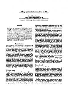
III. OPERATIONS OF A 3D GRAPHICS PIPELINE AND THEIR CHARACTERISTICS A 3D graphics pipeline is divided into two major phases: geometry processing and rendering. The inputs to the graphics pipeline are scene descriptions. The top level of scene descriptions consists of objects, light sources, materials, and textures. Each object is composed of primitives such as points, lines, and polygons, where the most commonly used primitives are triangles. A primitive is represented with a collection of vertices. Each vertex is associated with a set of properties, including coordinates (xyzw), normal (xyz), material index, and multiple sets of texture coordinates (rstq), most of which are FP quantities. Aside from the vertices, each object is associated with a set of transform matrices to be applied onto every vertex in that object. Light sources and materials are also each associated with a set of properties represented with FP or fixed point numbers. Textures are essentially one, two or three dimensional tables referenced by the texture coordinates. Each entry of the table contains a color value (which can also be interpreted in other ways) normally consisting of three (RGB) or four (RGBA) integer numbers. Managing the scenes and deciding which objects are to be shown are done by the applications. Processing and drawing of the scenes are done by the 3D graphics pipeline. The data flow of a typical 3D pipeline is shown in Figure 1. In the geometry processing phase, the vertices (coordinates and normals) are first transformed to eye space and lit, then transformed to clip space and assembled into triangles. The triangles are clipped against the view frustum, and finally the clipped triangles are transformed to the screen space. In the rendering phase, the triangles from the previous stage are rasterized into groups of pixels. During the rasterization step, the parameters associated with the vertices of a triangle are interpolated to obtain the parameters for each pixel in the triangle. These parameters include screen coordinates, depth, colors, texture coordinates, etc. The generated pixels then go though texture mapping, fogging, a series of tests, and alpha blending on a per-pixel basis. Finally the pixels are written to the frame buffer and form the final output image. Nowadays the implementation of the entire 3D pipeline is being moved to FP, since error accumulation in integer calculation can produce serious visual artifacts [11]. Singleprecision floating-point data representation is used in the 3D graphics processing pipeline due to its large dynamic range compared to fixed-point or integer data with the same number of bits. In this paper, we do not focus on the algorithmic aspects of the 3D pipeline, but rather its computational characteristics and their implications for ISA design. Therefore, we do not show the exact computations in 3D graphics, since these can change with different algorithms;
Clipping
Materials
Textures Scene Description
Application
Z Buffer, etc.
Rendering
Texture Cache
pixel Per-pixel Operations
Texture Mapping
Frame Buffer
Rasterization
Display
Figure 1 3D processing pipeline
We classify the basic operations in a 3D pipeline into the following categories. Data-parallel arithmetic operations perform the same calculation on multiple sets of data in parallel. Examples are parallel add, subtract, and multiply. Most operations on coordinates, normals, and colors fall into this category. A very common operation is the multiplication of a 4×4 matrix with a 4-element vector. Scalar arithmetic operations like add, subtract and multiply are used when computing coefficients in lighting and rasterization. Advanced math operations like reciprocal, reciprocal square root, and exponentiation are needed at various precisions. For example, computation of coordinates needs high precision in order to avoid visual artifacts, while color calculation requires lower accuracy. These operations are expensive to implement, therefore carrying out each of them in full precision is not necessary if lower precision is sufficient and less costly. Compare and conditionally executed operations are important in 3D graphics processing, although not very common. During the clipping step, vertex coordinates of vertices are compared to their bounding volume to check whether clipping is needed. New algorithms also allow vertices or pixels to be handled differently basing on their values, where compare and conditional execution is necessary. Conditional execution may be implemented with predicated execution, which is available in PLX. Memory access operations are intensive in the 3D graphics pipeline. They are used to import data into the pipeline, output processed triangles to the rendering phase, load textures, read and write the depth buffer and the frame buffer. The data in these accesses can be either FP or integer data. Data rearrangement operations do not alter the values of data, but rather change the order of data. They are convenient when reordering of data is needed to facilitate parallel computation. Data conversion operations are needed because when data are imported into the pipeline, they are not always in FP representation. For example, colors and textures are usually of integer types. The final rendered image is also in integer format. Therefore, proper data conversions need to be performed in various places in the 3D processing pipeline to convert integer to FP and vice versa.
501
TABLE I.
IV. PLX FP INSTRUCTIONS FOR 3D GRAPHICS The FP instructions of PLX are classified as follows: FMAC instructions, FP compare instructions, FP math approximation instructions, FP memory access instructions, FP data rearrangement and data conversion instructions. All instructions are 32 bits and the subword size is always 4 bytes, to represent a 32-bit single-precision FP number. There are 32 FP registers. Register F0 is hardwired to 0.0 and register F1 is hardwired to 1.0. Figure 2 shows the PLX FP datapath. The FP ISA continues the word size scalability feature of PLX, where the size of the registers can be 32, 64 or 128 bits, denoted PLX-32, PLX-64 and PLX-128, respectively. PLX32 has no subword-parallelism, PLX-64 has two subwords in each register, and PLX-128 has four. PLX-128 is the preferred implementation, because the register size matches the size of a 4-component FP vector, which is the most commonly used data type in the 3D graphics pipeline.
Instruction pfadd pfadd negate pfsubtract pfmultiply pfmultiply negate pfscale pfscale negate pfdotproduct pfdotproduct w/ satuation pfdotproduct negate pfdotproduct neg w/ sat pfabsolute pfabsolute negate pfmax pfmin pfmultiply-add pfmultiply-add negate pfmultiply-subract pfmultiply-subract negate pfscale-add pfscale-add negate pfscale-subtract pfscale-subtract negate
Register file
FMAC
Math approx unit
Data rearrangement unit
Figure 2 PLX FP datapath with three functional units: FMAC, math approximation unit, and data rearrangement unit
A. FMAC instructions The floating-point multiply-accumulate unit (FMAC) is the basic functional unit in FP processing. It can perform FP operations such as add, subtract, multiply and multiply-add. All the instructions in this class generate full-precision results. Table I shows the instructions and their descriptions. The mnemonics of subword-parallel instructions start with a “p”. For most subword-parallel instructions, the same operation is performed on every corresponding set of subwords in the registers, with the exception of pfscale instructions, where the first operands are always the j-th subword in the first source register. In pfdp instructions, the results are written to the rightmost subword in the destination register. There are also scalar versions of these instructions (not shown), where only the rightmost subwords in each register are used as operands. These instructions have the same mnemonics as the subword-parallel instructions but without the leading “p”. Notice that the scalar versions of pfscale instructions and pfmul instructions are equivalent. Therefore we only define fmul instructions for scalar operations. There are also no scalar versions for pfdp instructions. Less common instructions such as pfscale and pfdp instructions are included due to their usefulness in vector operations. pfscale and pfdp can be used to scale vectors and to take the dot product of two vectors, respectively, both of which are common in 3D graphics processing. pfscale and pfdp can be implemented with slight modifications to standard FMACs. pfabs instructions are useful in clipping. pfmin and pfmax instructions are useful in pixel operations, and are also easy to implement.
FMAC INSTRUCTIONS Description di=ai+bi di=−(ai+bi) di=ai−bi di=ai×bi di=−ai×bi di=aj×bi di=−aj×bi d=∑ai×bi d=∑ai×bi, d≥0 d=−∑ai×bi d=−∑ai×bi, d≥0 di=|ai| di=−|ai| di=max(ai, bi) di=min(ai, bi) di=ai×bi+ci di=−(ai×bi+ci) di=ai×bi−ci di=−(ai×bi−ci) di=aj×bi+ci di=−(aj×bi+ci) di=aj×bi−ci di=−(aj×bi−ci)
Mnemonic pfadd pfadd.neg pfsub pfmul pfmul.neg pfscale,j pfscale.neg,j pfdp pfdp.s pfdp.neg pfdp.neg.s pfabs pfabs.neg pfmax pfmin pfmuladd pfmuladd.neg pfmulsub pfmulsub.neg pfscaleadd,j pfscaladd.neg,j pfscalesub,j pfscalesub.neg,j
B. Compare instructions Compare instructions are used to generate conditions for later conditional executions. Compare instructions (see Table II) can also be implemented with the FMAC functional unit. Their definition parallels the integer compare instructions in PLX. The relation rel in the fcompare instructions can be any of eq(=), ne(≠), ge(≥), gt(>), le(≤), and lt(