The Cameleon Reference Framework [3] locates UI development steps for context-sensitive interactive applications. A context is defined as a triple of the form.
TAMODIA 2004 | PAPERS
15-16 November | Prague, Czech Republic
Addressing the Mapping Problem in User Interface Design with UsiXML Quentin Limbourg and Jean Vanderdonckt 1
Université catholique de Louvain, School of Management (IAG) Place des Doyens, 1 – B-1348 Louvain-la-Neuve (Belgium) {limbourg, vanderdonckt}@isys.ucl.ac.be – http://www.usixml.org Phone: +32-1047 {8379, 8525} – Fax: +32-10478324 ABSTRACT
Concrete user interface, Domain model, Final user interface, Mapping problem, Model mapping, Reification, Specifications, Task model, Transformation model, User interface description language, USer Interface eXtensible Markup Language (UsiXML).
The mapping problem has been defined as any method aimed at mapping models capturing various aspects of an interactive system throughout their development life cycle to support model-based design of user interfaces. This field has followed a long tradition of establishing models and maintaining mappings between them so as to create and maintain accurate specifications of a user interface. In this paper, potential mappings between models are defined so as to create a uniform and integrated framework of adding, removing, and modifying mappings throughout the development life cycle of interactive systems. The mappings can be established from any source model to any target model, one or many, in the same formalism, or from any model element to any other. Those models include task, domain, presentation, dialog, and context of use. The context of use is itself decomposed into user, platform, and environment. To support the manipulation of mappings between models, two examples of supporting software are detailed. TRANSFORMIXML consists of a Java application that triggers transformations of models expressed by graph grammars. IDEALXML consists of a Java application allowing the designer to edit any model at any time, and element of any model and to establish a set of mappings. Both software are based on UsiXML, a User Interface Description Language
INTRODUCTION
One approach existing in software development consists in establishing a model of the future software to be developed and to produce code from this model in a forward engineering manner. This approach largely contrasts with traditional approaches where the software is directly coded without any model or any specifications. This approach contrasts less with approaches where the software is specified and manually coded from the specifications. The development of the User Interface (UI), one component of the software, does not escape from this observation and lead to the approach of modelbased design of user interfaces. In this approach, a UI model is typically referred to as a set of concepts, a representation structure, and a series of primitives and terms that can be used to explicitly capture various forms of knowledge about the UI and its related interactive application using appropriate abstractions. A model is assumed to abstract selected concepts of the real world, but not all. Any concept of the real world can therefore lead to multiple abstractions depending on how each abstraction will be exploited in the future: descriptive (when the model is used primarily for specifications purposes) or generative (when the model is intended to be used for generating other information or code). The mapping problem has been defined as any method aimed at mapping models capturing these various concepts of an interactive system throughout their development life cycle to support model-based design of user interfaces [12,13]. In the mapping problem, models could be either descriptive or generative. In the same way, the relationships that can be established between models could be incorporated for specifications only (descriptive) or for producing more information such as other models and/or code (generative).
ACM Classification Keywords
D.2.2 [Software Engineering]: Design Tools and Techniques – user interfaces. H.2.4 [Database Management]: Systems – transaction processing. H.5.2 [Information Interfaces and Presentation]: User interfaces – graphical user interfaces, prototyping, screen design, user interface management systems. I.3.6 [Computer Graphics] Methodology and Techniques – interaction techniques. General terms: Design, Languages, Human Factors. Author Keywords:
Abstract
user
interface,
Abstraction,
Adaptation,
Permission to make digital or hard copies of all or part of this work for personal or classroom use is granted without fee provided that copies are not made or distributed for profit or commercial advantage and that copies bear this notice and the full citation on the first page. To copy otherwise, or republish, to post on servers or to redistribute to lists, requires prior specific permission and/or a fee.
So far, the main issues raised by the mapping problem, but not all, are the following: •
TAMODIA’04, Prague, Czeck Republic. Copyright ©2004 ACM 1-59593-000-0/04/0011…$5.00
155
Specific definitions of models and relationships: most of the time, each project and/or tool introduces its own definition of the models and the relationships between that only fit the local purposes of the project
TAMODIA 2004 | PAPERS
•
•
15-16 November | Prague, Czech Republic
expression of the renderings and manipulation of the domain concepts and functions in a way that is independent of the concrete interactors available on the targets. The elements used in the logical UI are abstractions of existing widgets. 3. Concrete User Interface (CUI): concretizes a AUI into Interaction Objects independent from the toolkit [16] so as to define widgets layout and interface navigation. This interface is now composed of existing UI widgets. 4. Final User Interface (FUI): The UI produced at the very last step of the reification process is supported by a multi-target development environment. A FUI is typically the UI code in any language, interpreted or compiled.
and/or tool, thus leaving little or no room for sharing and reusing them in another development context. Their specification definitions prevent them from being largely used by other development teams. The definitions remain mostly physical, not logical. Hard coding of models and relationships: most of the time, the models and the relationships between are hard coded in the supporting tools themselves, thus leaving limited flexibility for modifying the handling primitives (e.g., create, read, update, and modify a relationship) and the algorithms that can be developed around (e.g., an algorithm that automatically establishes relationships between a task model and a presentation model). Unequal handling of relationships: some tools actually include a real handling of the relationships between the models while some others only allow designers to establish mappings between models, but without any handling of them.
Context of use A
These shortcomings stem for the need for a logical definition of mappings based on a mathematical representation that further allows a computational handling of them (as suggested in [12]) as opposed to a physical handling hardcoded in particular software. The remainder of this paper is structured ad follows: the next section explains how some selected software address the mapping problem and what are the consequences of the way they handle the mappings. The third section introduces a structural definition of the mappings. The fourth section details how a logical definition of mappings can be established and ensured in a systematic way through a transformation-based engine. The fifth section concludes the paper.
Context of use B
n Task & Concepts
r Task & Concepts
o Abstract UI (AUI)
s Abstract UI (AUI)
p Concrete UI (CUI)
tConcrete UI (CUI)
q
u Final UI (FUI)
Final UI (FUI) Reification
Abstraction
Translation
Figure 1. The UI Reference Framework [3].
The downward arrows represent reification steps (forward engineering), from the more abstract to the operational interface. Reification is the transformation of a description (or of a set of descriptions) into a description (or a set of descriptions) whose level of abstraction is lower than that of the source one(s). In the multi-target reference framework, it is the inference process that covers the inference process from high-level abstract descriptions to run-time code. Upward arrows stand for abstraction steps. This process transforms any specifications into specifications at a higher level of abstraction. Here, abstraction is the elicitation of descriptions that are more abstract than the descriptions that serve as input to this process. Finally, horizontal arrows correspond to the translation of the interface from one type of platform to another, or more generally, from one context to another. Not all steps should be achieved in a sequential ordering dictated by the levels. Instead, locating what steps are performed, when, from which entry point and toward what subsequent step are important. In Fig. 2, transcoding tools start with a FUI for a source platform (q) and transforms it into another FUI for a target platform (u). Similarly, portability tools start with a CUI for a source platform (p) and transforms it into another CUI for another platform (t), that in turn leads to a new FUI for that platform (u). To overcome shortcomings identified for these tools, there is a need to raise the level of abstraction by working at the AUI level. UI Reverse Engineering abstracts any initial FUI (q) into concepts and relationships denoting a AUI (o), which can then be translated into a new AUI (s) by taking into account constraints and opportunities for the target
RELATED WORK
To present work related to the mapping problem with respect to a same reference, some significant and representative efforts made in existing environments supporting model-based approach have been selected. They are then presented according to a reference framework that represents the various levels and models where a UI development process may appear. The Cameleon Reference Framework [3] locates UI development steps for context-sensitive interactive applications. A context is defined as a triple of the form where E is an element of the environments set considered for the interactive system, P is an element of the platforms set considered for the interactive system and U is an element of the users set for the interactive system. A simplified version (Fig. 1) structures development for two contexts of use, here for two platforms: the one on the left represents the source and the one on the right represents the target. The development process can be decomposed into four steps: 1. Task and concepts: describe the various tasks to be carried out and the domain-oriented concepts as they are required by these tasks to be performed. 2. Abstract User Interface (AUI): a canonical
156
TAMODIA 2004 | PAPERS
15-16 November | Prague, Czech Republic
models and relationships in a syntax-directed editor (Fig. 2). In this way, the editor remains independent of any introduction of any model and relationship, but it does not provide any graphical representation of the corresponding models nor does it exploit the semantics of these relationships for further development. In terms of the Cameleon reference framework, the XIML editor supports editing the “Task & Concepts” level, the AUI level, the CUI level and mappings between, but no computational handling of them.
platform. UI Forward Engineering then exploits this AUI (s) to regenerate a new AUI adapted to this platform, by recomposing the CUI (t) which in turn is reified in an executable FUI (u). The TADEUS (Task Analysis/Design/End User Systems) approach [6,15] provides a model-based framework for representation, a methodology, and a corresponding environment for user interface development. The inputs for this approach have been provided by techniques from workflow modeling as well as by user interface description languages, aiming at task-based and useroriented development of interactive software. The basic design activities in TADEUS start with a specification of the task and user (role) model according to the organisation of work. Then, a data model is derived from these models, followed by migrating interaction features with the previous results. Finally, either prototyping with end users might be performed, or code may be generated from the integrated object-oriented representation. TADEUS supports modeling of the following aspects: task, user, data, interaction, and application. More recently, a workflow model has been incorporated to relate existing models in the global modeling of the organisation. TADEUS allows the designer to establish relationships of the types summarised in Table 1, but no handling exist in the tool to exploit the semantics of these relationships, e.g. to derive a new model. Furthermore, there is no true definition of the semantics of these relationships. On the one hand, this allows some flexibility of use, but on the other hand, it prevents from rigorous and systematic applying. In terms of the Cameleon reference framework, TADEUS editor supports editing the “Task & Concepts” level, the CUI level, and the generation of a FUI. Set up
Employ, has
Reification & abstraction Is a, has part
Relate
Figure 2. The XIML basic editor.
The problem of multiple coordinated representations of a UI model has been addressed in the FormsVBT environment [1]. At any time, a GUI is represented by its corresponding specifications in the FormsVBT language, largely inspired by TeX and by a hierarchical view of the UI composition (Fig. 3). At any time, the designer can change the FormsVBT specifications and see the hierarchical view changed accordingly and vice versa. Any change is any view is immediately propagated in the other views, thus maintaining a bijection between all representations.
Handles, creates, concerns, informs, controls, requires, before, is based on, corresponds to, is attached to
Table 1. Semantic relationships in TADEUS.
XIML is a User Interface Description Language (UIDL) that supports expressing several UI models simultaneously and relationships between them. In its standard definition, it contains information for basic models, called canonical models, i.e. the task, the user, the presentation, the dialog, and the platform. XIML is very unique in its capability to introduce in any XIML specifications the definition and the statement of any model and any relationship, even custom models and relationships. Thanks to the definition of a ‘general purpose’ model, XIML can introduce any new model that was not defined before. On the one hand, this provides a significant advantage of openness and flexibility. On the other hand, it means that if this definition is not shared by other tools, the definition will remain local. The basic XIML editor supports all canonical and user-defined
Although this bijection is certainly desirable, it is hard to achieve it for every UI model which may hold a different graphical representation or several ones. In terms of the Cameleon reference framework, FormsVBT maintains a tight coupling between the CUI and the FUI levels of a GUI. The definition of the relationships between the CUI and the FUI levels are not made salient, but are maintained internally in the tool at any time.
157
TAMODIA 2004 | PAPERS
15-16 November | Prague, Czech Republic
structure of many task model ordering constraints. The mapping rules can also use environmental information, such as the target display medium, to affect the characteristics of the generated PM layout. In addition to defining mappings between tasks and Beans, the mapping rules define which layout manager should be used by each container Bean.
Figure 3. The two views in the FormsVBT editor [1].
Vista [2,5] enables the designer to define mappings between four views of the same interactive system (Fig. 4): a task model consisting of a recursive decomposition of the task into sub-tasks, a CUI model, specifications of the interaction in terms of the UAN notation, and specifications of the architecture. Some of these relationships can be established and maintained semiautomatically by Vista. Again, no logical definition of them is made explicit.
Figure 5. The various views in the TEALLACH environment [7].
STRUCTURAL DEFINITION OF MAPPINGS
Ideally, a model should be declarative rather than imperative or procedural. It should also be editable, preferably through tools, and finally it should be analysable, so as to allow some degree of automation. A model consists of a number of features (Fig. 6). It is typically built as a hierarchical decomposition of abstract concepts into more refined sub-concepts. Any concept can then be characterized by a name, a description and properties of interest. A model should also encompass relationships between these concepts with roles. These relationships apply both within models (called intramodel relationships) and between models (called intermodel relationships). Any of these relationships (i.e., the definition, the decomposition, the intra- or inter-model relationships) can possess a number of attributes. DECOMPOSITION Is decomposed into
Figure 4. The various views in the VISTA environment [2,5].
Teallach [7] uses mapping rules in several places in its architecture to allow mappings between the various models (Fig. 5). For example, a set of mapping rules exist between the task model and its abstract presentation model counterpart. In addition to these mappings, an additional set of rules exist between the abstract and concrete presentation models. These mapping rules take into consideration the information captured in the user model, to provide the intended users of the system with a generated interface suitable to their requirements. These mapping rules are simple in nature, selecting from a 1:m correspondence between abstract PM concepts and PM Beans. The mapping rules consult the UM to decide which Bean from those applicable should be used, and reflect the implicit
MODEL
DEFINITION
Features
Definition attributes
Decomp. attributes 0-n
CONCEPT
Is composed of
0-n
Name Description Properties
MODEL RELATION CONCEPT RELATION Relation features Concept rel. attributes
Figure 6. Definition of the user interface model.
How many models do we need? A single UI model is probably too complex to handle because it combines all static and dynamic relationships in the same model. It is also preferable to avoid using a large number of models, because this requires establishing and maintaining a large number of relationships between the models. Model separability is desirable in this case. Model separability adheres to the Principle of Separation of Concerns, which states that each concept should be clearly separated from the others and classified in only one category.
158
TAMODIA 2004 | PAPERS
15-16 November | Prague, Czech Republic
Several Application Programming Interfaces are available to perform model-to-model transformations (e.g., DMOF at http://www.dstc.edu.au/Products/CORBA/MOF/ or Univers@lis at http://universalis.elibel.tm.fr/site/). Attributed Graph Grammars (AGG) API was selected due to our prior experience with its GUI version. Using AGG API as a transformation tool allows us to realize the following scenario (Fig. 7): an initial model along with a set of rules expressed in UsiXML is transmitted to TransformiXML API. UsiXML elements (models and rules) are parsed and transformed into AGG object types. Rules are successively applied to the models. The resulting specification, under the form of AGG objects, is parsed and transformed into UsiXML elements [8,10].
Therefore, the quality of separability depends on the desired results and the human capacity to properly identify and classify concepts. Separability is hereby defined as the ability of a model to classify any abstraction of a real world aspect of interest into one single model (based on the Principle of Separation of Concerns). Correlability is hereby defined as the ability of two or more models to establish relationships between themselves so as to represent a real world aspect of interest. To ensure separability or correlability, a series of relationships is required with respect to their source and target models from a structural point of view (Table 2).
....
USIXML specification (initial)
Transformation API
rules applied ::=
Transformation rules expressed in USIXML
....
USIXML specification (resultant)
Figure 7. Development process based on transformation application.
TransformiXML GUI
The specific requirements of this component are: • To manage a development library (a library containing a catalog of transformation rules). • To associate development sub-step with transformation systems. • To execute transformations in an interactive manner. Fig. 8 presents a prototype of TransformiXML. The basic flow of tasks with TransformiXML GUI is the following: a user chooses an input file containing models to transform. She, then, chooses a development path by selecting a starting point and a destination point (e.g., the viewpoint to obtain at the end of the process). Depending on the content of the input file some of the development paths may not be available. A tree allows the user to visualize the proposed development model (i.e., all the steps and sub-steps for a chosen path). The user can load another development model for the selected path. Now the task of the user consists in attaching one transformation system for each development sub-step. By clicking on a sub-step in the tree, a set of transformation systems realizing the chosen sub-step are displayed. A transformation system may be attached to the current substep by clicking “Attach to current sub-step”. The user may also want to edit the rules either in an XML editor (the one of grafiXML, for instance) or in AGG environment. After attaching a transformation system for each rule in the development model, the user may apply the transformation either step by step or as a whole. The result of the transformation is then explicitly saved in a UsiXML file. In the next section, we exemplify what kind of relationships can be established between models depending on their types.
Table 2. Table of potential mapping types.
THE TRANSFORMIXML ENVIRONMENT
TransformiXML [8] is an environment that addresses the mapping problem (any type of structural mapping) by supporting a mathematical expression of the relationships (based on graph grammars) and allowing the definition and the application of transformation rules. This environment is sub-divided into two components [8,10]: an Application Programming Interface (TransformiXML API) hat can be used by any application to apply transformation rules in a batch-like way (non interactive) and a Graphical User Interface that serves as a front-end application to the API (TransformiXML GUI) in an interactive way. Those two components are further described in the next sub-sections and an example illustrates how the second component can drive a transformation process involving several models in a UI development process. Both components share a generic requirement: to manipulate any UI description model expressed in USer Interface eXtensible Markup Language (UsiXML – http://www.usixml.org) and to apply transformation rules in the models contained in this description. TransformiXML API
The specific requirement of this component is the following: to be enable the interpretation of transformation rules from a UsiXML description of rules and host models. 159
TAMODIA 2004 | PAPERS
15-16 November | Prague, Czech Republic
Mappings between the domain model and the UI models
is an abstraction of which concrete object. Is Executed In maps a task to an interaction object (a container or an individual component) allowing its execution. This relationship is notably useful for deriving a dialog control component, for ensuring that all tasks are supported appropriately by the system.
Several relationships can be defined to explicit the relationships between the domain model and the UI models (both abstract and concrete): Observes is a mapping defined between an interaction object and a domain model concept
Figure 8. The front-end interface of TransformiXML.
(either an attribute, or an output parameter of a method). This mapping may be interpreted as follows: the content of a UI object must be synchronized when - A mapped attribute is modified. The new state resulting from this modification should be presented on the UI (the notion of view could be of interest). - A mapped method is executed. Its output parameters are displayed on the UI. Updates is a mapping defined between an interaction object and a domain model concept (specifically, an attribute). “Updates” describes the situation where the attribute of an object in the domain model must be synchronized with the content of a UI object. Triggers is a mapping defined between an interaction object and a domain model concept (specifically, an operation). This mapping describes that a UI object is able to trigger a method from the domain model.
Is Reified By indicates that a concrete object is the reification of an abstract one through a reification transformation. Is Abstracted Into indicates that an abstract object is the reification of a concrete one through an abstraction transformation. Is Adapted Into indicates that an interaction object (abstract or concrete) is adapted into another one as a result of an adaptation transformation.
Other mappings
Other useful mappings are: • Manipulates maps a task to a domain concept. It may be an attribute, a set of attributes, a class (or an object), or a set of classes (or a set of objects). This relationship is useful when it comes to find the most appropriate interaction object to support a specific task. • Has Context maps any model element to one or several contexts of use.
Mappings for traceability of the development cycle
EXAMPLE OF MAPPING HANDLING
Our ontology is designed to be integrated in a framework where models are transformed into other models. This framework defines several types of transformations in order to achieve multi-path development of UIs. Traceability mappings are helpful for keeping a trace of the execution of the transformations. For instance it may be interesting to know which concrete object reifies which abstract object, or vice versa, which abstract object
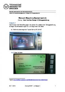
Fig. 9 depicts manipulates relationships between the task and the domain model as dashed arrows. Provide Personal Data is mapped onto Participant class. Show Question is mapped onto the attribute title of class Question. The task Select Answer is mapped onto the attribute title of the class Answer.
160
TAMODIA 2004 | PAPERS
15-16 November | Prague, Czech Republic
And finally, the task Send Questionnaire is mapped onto the method sendQuestionnaire of the class Questionnaire. Fig. 10 depicts a mapping exploiting the “manipulates” relationship between a task and an attribute of the domain model and a “isExecutedin” relationship between a task model and components of an AUI. The transformation rule states that: for each task creating an element, manipulating a domain attribute and being executed in an abstract individual component, there should be in this component a facet for allowing the end user to input the value of that domain attribute. Note that this
NAC
LHS
RHS
::=
Figure 10. Transformation rule for creating an input facet to any abstract individual component that realise creation tasks. The transformation rule depicted in Fig. 11 can be fired
Figure 9. Relationships between a task model and a domain model.
NAC
LHS
RHS
::=
Figure 11. Relationships between a task model and a domain model.
and executed by TransformiXML subsequently to the rule of Fig. 10. This rule states: each time there is a need to input an alphanumeric value (component for creating the value of a string), a group box should be generated that contains a non-editable text containing the label followed by an editable text for accepting the future value. In addition the relationship “isReifiedBy” ensures some traceability by keeping the information that this group box has been generated at the CUI level for each such
transformation rule does not specify how this facet will be implemented since we remain at the AUI level. It is the responsibility of another rule to map this facet to some widgets for creating a CUI that will be in turn reified into a FUI. Also note that traceability is ensured thanks to the “isExecutedIn” relationship.
161
TAMODIA 2004 | PAPERS
15-16 November | Prague, Czech Republic
289–308. 4. Eisenstein, J., Vanderdonckt, J., and Puerta, A.R. Model-Based User-Interface Development Techniques for Mobile Computing. Proc. of 5th ACM Int. Conf. on Intelligent User Interfaces IUI’2001 (Santa Fe, 14-17 January 2001). ACM Press, New York (2001), 69–76. 5. Elnaffar, S.S. and Graham, T.C.N. Semi-Automated Linking of User Interface Design Artifacts. In: Kolski, Ch., Vanderdonckt, J. (eds.), Proc. of 3rd Int. Conf. on Computer-Aided Design of User Interfaces CADUI'99 (Louvain-la-Neuve, 21-23 October 1999). Kluwer Academic Pub., Dordrecht (1999). 6. Elwert, T. and Schlungbaum, T. Modelling and Generation of Graphical User Interfaces in the TADEUS Approach. Proc. of the 2nd Int. Worskhop on Design, Specification, and Verification of Interactive Systems DSV-IS’95 (Château de Bonas, 79 June 1995). Springer-Verlag, Vienna (1995), 193– 208. 7. Griffiths, T., Barclay, P., Paton, N.W., McKirdy, J., Kennedy, J., Gray, P.D., Cooper, R., Goble, C., and Pinheiro da Silva, P. Teallach: a Model-based User Interface Development Environment for Object Databases. Interacting with Computers 14, 1 (2001) 31–68. 8. Limbourg, Q., Vanderdonckt, J., Michotte, B., Bouillon, L. and Lopez, V., UsiXML: a Language Supporting Multi-Path Development of User Interfaces. Proc. of 9th IFIP Working Conf. on Engineering for Human-Computer Interaction jointly with 11th Int. Workshop on Design, Specification, and Verification of Interactive Systems EHCI-DSVIS’2004 (Hamburg, 11-13 July 2004). Kluwer Academic Press, Dordrecht (2004). 9. Limbourg, Q., Vanderdonckt, J., Michotte, B., Bouillon, L., Florins, M. and Trevisan, D. UsiXML: A User Interface Description Language for ContextSensitive User Interfaces. Proc. of the AVI’2004 Workshop “Developing User Interfaces with XML: Advances on User Interface Description Languages” UIXML’04 (Gallipoli, 25 May 2004). EDM-Luc, Diepenbeek (2004), 55–62. 10. Limbourg, Q., Multi-path Development of User Interfaces, Ph.D. thesis, Université catholique de Louvain, Institut d’Administration et de Gestion, Louvain-la-Neuve, 4 November 2004. 11. López-Jaquero, V., Montero, F., Molina, J.P., Fernández-Caballero, A. and González, P. Model-Based Design of Adaptive User Interfaces through Connectors. Proc. of 10th International Workshop on Design, Specification, and Verification of Interactive Systems DSV-IS’ 2003 (Funchal, 11-13 June 2003). Lecture Notes in Computer Science, Vol. 2844. Springer-Verlag, Berlin (2003), 245–257. 12. Puerta, A.R. and Eisenstein, J. Towards a General Computational Framework for Model-Based Interface Development Systems. Knowledge-based Systems 12 (1999), 433–442. 13. Puerta, A.R. and Eisenstein, J. Towards a General Computational Framework for Model-Based Interface
component at the AUI level. A potential corresponding CUI is depicted in Fig. 12 Participate to Opinion Poll Provide Personnal Data
Answer Question
Content to determine at run-time
create name Question create zipCode
Select Answer Answer
select sex Female
Send Questionnaire
Male select ageCategory 18-35 35-45 45+
Figure 12. Graphical representation of the resulting Concrete User Interface. CONCLUSION
The major benefit of addressing the mapping problem in TransformiXML is that all the design knowledge required to progressively move from abstract models to concrete models, and ultimately the FUI can be expressed through rules that can then be automatically applied on demand. Contrarily to TransformiXML, the designer may want to establish and maintain relationships between the models in a manual way so as to maximize the control over the development life cycle in a way that is more opportunistic. IdealXML is another software based on UsiXML that has been developed for this purpose. At any time it can maintain the relationships defined, but no automation is provided. ACKNOWLEDGMENTS
We gratefully acknowledge the support of the Cameleon research project (http://giove.cnuce.cnr.it/cameleon.html) under the umbrella of the European Fifth Framework Programme (FP5-2000-IST2) in which the UsiXML language (http://www.usixml.org) has been defined and the SIMILAR network of excellence (http://www.similar.cc), the European research task force creating human-machine interfaces similar to humanhuman communication of the European Sixth Framework Programme (FP6-2002-IST1-507609). REFERENCES
1.Avrahami, G., Brooks, K.P. and Brown, M.H. A Twoview Approach to Constructing User Interfaces. Proc. of the 16th Annual Conf. on Computer Graphics and Interactive Techniques SIGGRAPH’89 (Boston, 31 July-4 August 1989). Comp. Graphics 23, 3 (July 1989), 137– 146. 2. Brown, J., Graham, T.C.N., and Wright, T. The Vista Environment for the Coevolutinary Design of User Interfaces. Proc. of ACM Conf. on Human Factors in Computing Systems CHI’98 (Los Angeles, 18-24 April 1998). ACM Press, New York (1998), 376–383. 3. Calvary, G., Coutaz, J., Thevenin, D., Limbourg, Q., Bouillon, L. and Vanderdonckt, J. A Unifying Reference Framework for Multi-Target User Interfaces. Interacting with Computers 15, 3 (2003), 162
TAMODIA 2004 | PAPERS
15-16 November | Prague, Czech Republic
Development Systems. Proc. of the 4th ACM Conf. on Intelligent User Interfaces IUI’99 (Los Angeles, 5-8 January 1999). ACM Press, New York (1999), 171– 178 14. Puerta, A.R. and Eisenstein, J. XIML: A Multiple User Interface Representation Framework for Industry. Chapter 7. In Seffah, A., Javahery, H. (eds.), Mutiple User Interfaces: Cross-Platform Applications and Context-Aware Interfaces. John Wiley & Sons, (2003). 15. Stary, Ch. Meeting Activity Theory through Taskbased and User-Oriented Development of User
Interfaces. In Kolski C., Vanderdonckt J. (eds.), Proc. of 3rd Int. Conf. on Computer-Aided Design of User Interfaces CADUI‘2002 (Valenciennes, 15-17 May 2002), Computer-Aided Design of User Interfaces III. Kluwer Academic Pub., Dordrecht (2002), 193–204. 16. Vanderdonckt, J. and Bodart, F. Encapsulating Knowledge for Intelligent Automatic Interaction Objects Selection. Proc. of the ACM Conf. on Human Factors in Computing Systems INTERCHI'93 (Amsterdam, 24-29 April 1993). ACM Press, New York (1993), 424–429.
163